 Skip to content


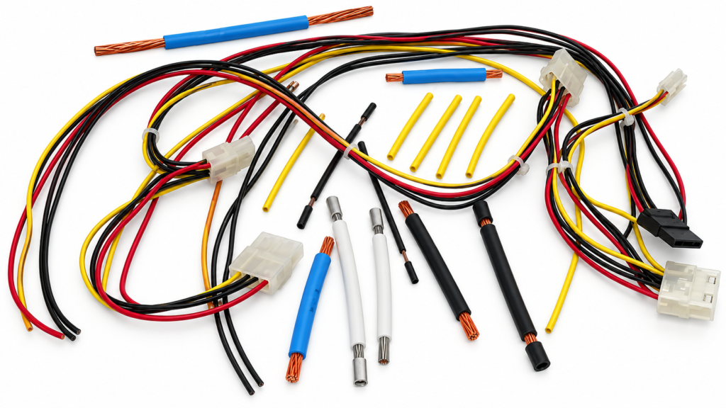
A machinery wire harness can look deceptively simple when it is lying on a table. Several cables, a few connectors, some protective sleeving, labels, and branch points may appear easy to price. In reality, two harnesses that look almost identical can require different connector systems, conductor sizes, shielding, seals, terminal processing, protection methods, testing, tooling, packaging, and assembly time. That is why reliable quotations begin with specifications rather than photographs or approximate descriptions alone.
To quote a machinery wire harness accurately, the manufacturer normally needs a drawing or reference sample, BOM, wire specifications, connector and terminal details, pinout, dimensions, application conditions, protection requirements, testing criteria, target quantity, packaging requirements, and relevant compliance or documentation requirements. The more clearly these inputs are defined, the fewer assumptions remain inside the quotation.
A complete engineering package is ideal, but many real projects do not begin that way. A machine builder may have an existing harness, an electrical schematic, several connector photographs, and a marked-up PDF instead of a finished production drawing. A supplier-transfer project may have an old BOM but incomplete revision history. The important issue is not whether every file is perfect on day one; it is whether missing information can be identified before assumptions become embedded in the quoted price, sample, tooling, or production process. Cablivo’s documented project scope includes drawing review, BOM review, connector confirmation, pinout review, sample development, testing discussion, packaging, labeling, and production preparation.
The consequences of an unclear RFQ usually appear later. A connector assumed to be interchangeable turns out to require an exact manufacturer part number. A branch dimension was measured from the wrong reference point. A cable described only as “flexible” actually moves continuously with a machine axis. A quotation based on continuity testing later receives additional insulation or mechanical test requirements. None of these changes sounds dramatic in isolation, but each can alter material cost, labor, tooling, testing time, or lead-time planning. Accurate quoting is therefore less about producing a number quickly and more about removing the assumptions that can change that number later.
What Documents Are Needed for a Machinery Wire Harness Quote?
An accurate machinery wire harness quote normally starts with a controlled drawing, BOM, wire or circuit list, connector information, pinout, revision status, test requirements, and quantity. When a complete production drawing is unavailable, an existing harness, clear photographs, schematics, dimensions, connector details, application information, and target quantity can still provide a practical starting point for engineering review.
The document package is the shared technical language between the machine designer, procurement team, engineering team, and harness manufacturer. Its purpose is not to make an RFQ look more formal. It should establish one consistent product definition that can be translated into material purchasing, wire preparation, terminal processing, assembly, testing, inspection, packaging, and production planning without repeatedly asking the customer to clarify basic information.
A large number of files does not automatically make an RFQ better. Inconsistent information can create more uncertainty than a smaller, well-controlled package. A drawing may show one connector revision while the BOM lists another. A circuit list may specify one conductor size while an older schematic shows something different. A photograph may reveal protective sleeving that is absent from the drawing. Before quotation, these conflicts should be identified and resolved instead of allowing each department or supplier to make its own interpretation.
| RFQ Item | Minimum Useful Information | Stronger Quotation Package | Main Risk If Missing |
| Harness drawing | Overall layout and connector locations | Branch dimensions, tolerances, protection, labels, revision | Incorrect geometry or labor estimate |
| BOM | Main components | Manufacturer part numbers, quantities, approved alternatives | Material price assumptions |
| Wire list | Wire ID and endpoints | AWG/mm², color, type, length, terminal | Incorrect conductor or processing cost |
| Pinout | Cavity-to-cavity mapping | Connector face views and circuit names | Crossed or misunderstood circuits |
| Connector data | Housing model | Terminal, seal, lock, backshell and accessory data | Incomplete connector cost |
| Test requirement | Basic electrical test | Limits, frequency and acceptance criteria | Testing added after quotation |
| Sample/photos | General appearance | Connector faces, branches, labels and scale reference | Hidden construction features |
| Revision information | Current file date | Drawing, BOM and pinout revision alignment | Quote based on obsolete specification |
Drawing and Revision Control
A useful harness drawing should define more than the general shape of the assembly. It should show the connectors, branch structure, important dimensions, wire or cable routing, protection components, labels, clips, heat-shrink locations, connector orientation, and any dimensions that directly affect installation. When the harness must fit around frames, panels, sensors, motors, or moving machine elements, physical layout can be just as important as the electrical circuit.
Revision control becomes especially important during prototype development and machine design changes. If a project has already progressed from Rev. A to Rev. C, every controlled file used for quotation should be checked against that current release. A Rev. C drawing combined with a Rev. A BOM can result in a technically detailed quotation for the wrong assembly. Keeping drawing, BOM, pinout, test requirements, and label files aligned under one revision reduces avoidable confusion before sampling and mass production.
BOM, Wire List, and Pinout
A BOM describes what materials become part of the harness, while the wire list and pinout explain how those materials are connected. The BOM may include wires, multicore cables, connector housings, contacts, terminals, seals, backshells, heat shrink, braided sleeving, conduit, labels, ties, clips, molded parts, and other specified components. A vague line such as “industrial connector” leaves too much room for interpretation when exact connector systems can vary significantly in price and assembly requirements.
The wire or circuit list should identify each circuit clearly enough for both production and testing. Useful information can include wire number, conductor size, color, source, destination, terminal, and circuit identification. The pinout then defines the exact connector cavity for that circuit. Together, these files allow the manufacturer to distinguish a straightforward cut-and-crimp harness from an assembly requiring sealed contacts, shield preparation, multiple connector systems, special branch construction, soldering, or additional protection operations.
Connector and Sample Information
Connector photographs or an existing harness can be extremely useful when machinery documentation is incomplete. Clear photographs should show connector markings, front mating faces, rear wire-entry sides, locking features, seals, backshells, and cable exit directions. Multiple angles are preferable when the connector family or accessory structure is difficult to identify from one view. A scale reference can also help when dimensions are not immediately available.
An existing harness may reveal construction details that never appeared in the original engineering files, such as sleeve length, branch stiffness, heat-shrink position, tie location, connector protection, or cable routing behavior. It should still be reviewed cautiously because an installed harness may have been repaired, stretched, contaminated, or modified during years of machine maintenance. The sample is most useful as physical engineering evidence rather than automatically being treated as an error-free production master.
When Drawings Are Incomplete
Replacement harnesses, legacy machinery, supplier-transfer programs, and early equipment prototypes frequently begin without a complete production package. In those cases, the project can start with what is available, including sample photographs, connector photographs, electrical schematics, cable lengths, application information, and target quantity. The manufacturer can then identify which specifications remain open before sampling or final quotation instead of asking the customer to invent missing technical details.
Cablivo’s documented project guidance specifically allows incomplete drawing packages to begin with sample photos, connector photos, cable length, application details, and target quantity for initial review. The important distinction is between an early engineering estimate and a production-ready quotation. As the project progresses toward sample approval and bulk manufacturing, drawings, BOM, pinout, test requirements, labels, and revision status should become increasingly controlled.
Which Wire and Connector Specifications Must Be Confirmed?
The quotation should define conductor size, wire or cable type, cut lengths, connector housings, terminals, seals, pinout, protective materials, branch construction, and any overmolded or strain-relief features. These details influence both direct material cost and the manufacturing operations required for cutting, stripping, crimping, soldering, sleeving, heat shrinking, molding, assembly, testing, and final inspection.
Electrical function alone does not fully define a machinery harness. Two assemblies may connect the same devices yet require very different materials and production processes. One might use unsealed connectors and fixed single-core wires inside a protected control cabinet, while another uses shielded multicore cable, sealed contacts, braided sleeving, multiple branches, molded strain relief, and carefully controlled dimensions. Both may perform the same basic electrical connection, but their cost structures and production risks are very different.
Conductor size also should not be selected only from habit or appearance. Current carrying requirements depend on the complete electrical and installation context, including conductor construction, insulation, ambient temperature, bundling, duty cycle, voltage drop, terminal compatibility, and relevant equipment requirements. The AWG figures below are therefore useful dimensional references rather than universal current ratings or recommendations for every machine.
| Conductor Size | Approx. Copper Area | Common Project Use Example | What Must Still Be Confirmed |
| 24 AWG | 0.205 mm² | Low-current signal and control circuits | Current, voltage drop, temperature, flexing |
| 22 AWG | 0.326 mm² | Sensors and control wiring | Terminal compatibility and circuit load |
| 20 AWG | 0.518 mm² | Controls and moderate-current circuits | Bundle conditions and connector rating |
| 18 AWG | 0.823 mm² | Control or power branches | Actual load and installation conditions |
| 16 AWG | 1.31 mm² | Higher-current equipment circuits | Protection, temperature and terminals |
| 14 AWG | 2.08 mm² | Power distribution branches | Equipment requirements and connector capacity |
| 12 AWG | 3.31 mm² | Higher-current power connections | Thermal design and termination system |
| 10 AWG | 5.26 mm² | Larger power circuits | Complete electrical and mechanical validation |
Wire Gauge and Cable Construction
Wire gauge is only one part of the specification. A machinery harness may contain discrete control wires, power conductors, multicore cables, sensor cables, communication lines, or shielded signal cables within the same assembly. Each circuit can have different requirements for insulation, flexibility, shielding, jacket construction, temperature exposure, or mechanical protection, so one generic instruction such as “industrial cable” is rarely enough for a production quotation.
A 20 AWG wire remaining stationary inside a control cabinet does not have the same mechanical job as a similarly sized conductor repeatedly moving with a machine axis. Likewise, a signal cable routed beside motors or drives may require a different construction from a basic digital control circuit. Final AWG, temperature rating, oil resistance, flame performance, and similar specifications should therefore be confirmed against the actual machinery application and project requirements instead of being assumed from a general product category.
Lengths, Branches, and Tolerances
Length specifications should clearly define where measurements begin and end. A branch described as 500 mm long can be interpreted differently if one person measures from the connector mating face while another measures from the rear housing, branch breakout center, sleeve edge, or exposed wire end. In a multi-leg machinery harness, small differences can become significant when branches need to reach sensors, switches, motors, or panel connectors positioned along a fixed machine frame.
Not every dimension needs the same tolerance. An overall cable leg that has extra service loop may allow more variation than a short branch entering a restricted enclosure or aligning with a row of mounted sensors. Identifying which dimensions are installation-critical allows manufacturing and inspection resources to focus on features that matter instead of applying unnecessarily tight tolerances to the entire harness.
Connector, Terminal, and Seal Selection
A connector housing may represent only one part of the complete connector system. Depending on the design, the finished assembly may also require terminals or contacts, individual wire seals, cavity plugs, secondary locks, wedges, backshells, boots, strain-relief components, or related accessories. If the design requires an exact manufacturer and part number, the RFQ should state that clearly so quotations do not silently substitute a different component family.
Equivalent parts should also be handled deliberately. If alternatives are acceptable, define which characteristics must remain unchanged and which substitutions need approval. This is particularly important when comparing supplier quotations because one price may include the specified branded connector while another assumes a lower-cost compatible version. Connector confirmation should therefore review housing, contacts, seals, accessories, wire compatibility, and pinout together rather than treating the connector as one isolated BOM line.
Protection and Overmolded Structures
Sleeving, conduit, heat shrink, cable glands, molded connector exits, and strain-relief structures can materially change the production process. Adding braided sleeving may introduce cutting, termination, branch preparation, and heat-shrink operations. An overmolded connector may require tooling, material confirmation, mold trials, dimensional checks, cable exit control, and sample validation before the design is stable enough for repeatable production.
These features normally have a functional purpose in machinery applications. They may protect a termination area, organize branches, reduce abrasion exposure, support strain relief, control the cable exit direction, or provide a more repeatable protective structure. Cablivo’s documented capabilities include connector confirmation, pinout review, terminal processing, overmolding, tooling discussion, and related cable assembly operations. Final construction still needs to follow the actual machine requirements rather than applying molded or protective features automatically.

How Do Machinery Application Conditions Affect the Quote?
Machinery operating conditions help determine whether the proposed harness construction is actually suitable. The RFQ should explain movement, vibration, abrasion, temperature, moisture, oil or chemical exposure, routing restrictions, and possible electrical interference. These conditions can change conductor construction, jacket material, shielding, protective sleeving, connector selection, strain relief, routing design, and the validation tests needed before production.
A machinery wire harness is not used on a drawing; it is installed inside real equipment. One branch may remain protected inside an electrical cabinet while another passes near a motor, enters a moving cable carrier, crosses a metal frame, or connects to sensors exposed to coolant and machine vibration. Treating the entire harness as though every section experiences the same environment can either create unnecessary cost or leave a critical branch under-protected.
Terms such as “heavy duty,” “industrial grade,” “waterproof,” or “oil resistant” sound convenient but do not define real operating conditions. A useful application description explains where the harness is installed, how it moves, what it may contact, and what failure risks matter to the equipment. This gives the manufacturer a better basis for reviewing materials, connector systems, protection methods, and testing without creating unsupported performance claims.
| Application Condition | Useful RFQ Information | Example Project Description | Possible Design Impact |
| Movement | Fixed, occasional or repeated | Harness follows a moving machine axis | Flexible conductor and cable review |
| Bend path | Radius and travel where known | Routed through cable carrier | Jacket and flex construction |
| Vibration | Location and severity information | Mounted near motor or pump | Terminal retention and strain relief |
| Abrasion | Contact points | Harness crosses metal frame edge | Sleeve, conduit or routing protection |
| Temperature | Operating and storage requirements | Near motor, heater or enclosure | Insulation and jacket selection |
| Fluids | Oil, coolant, water or cleaner | CNC or processing area | Material compatibility discussion |
| EMI environment | Motors, VFDs or power cables nearby | Sensor circuit close to drive | Shielding and grounding review |
| Routing space | Channels, clamps and bend limits | Narrow electrical cabinet | Connector orientation and branch layout |
Fixed and Moving Harnesses
One of the first application questions should be whether the harness remains stationary during normal machine operation. A fixed harness may move only during installation or maintenance, while a dynamic harness may repeatedly bend with a sliding axis, robotic arm, rotating station, lift mechanism, or cable carrier. These applications should not be evaluated under the same assumptions simply because both use flexible wire.
For moving applications, useful information includes travel distance, approximate bend radius, motion direction, available cable-carrier space, torsion if present, mounting method, and expected operating profile. If the equipment design already defines a required bending life, that requirement should be supplied for review. Arbitrary flex-cycle numbers should not be added merely to make a specification look demanding, because durability targets need to reflect real machinery movement and the agreed validation method.
Temperature, Fluids, and Moisture
Temperature is often more complex than one maximum number. A harness may experience one environment during normal operation, another during storage, and localized heating near motors, power components, heaters, or enclosed electrical areas. Providing realistic operating and storage conditions gives the manufacturer more useful information than simply requesting the highest temperature rating available, which may increase cost without improving the actual machine design.
Fluid exposure needs similar detail. Occasional oil splash is different from continuous coolant exposure, hot lubricant, hydraulic fluid, aggressive cleaning agents, or outdoor moisture. The same applies to water-related requirements: condensation, splash, washdown, rain exposure, and immersion represent different design cases. If a defined sealing or environmental performance requirement applies, the connector type, sealing structure, material, and verification method should be reviewed against that real requirement rather than relying on a broad “waterproof” description.
Routing, Vibration, and Abrasion
Electrical correctness does not guarantee that a harness will install correctly or survive its environment. A branch routed through a sharp sheet-metal opening may need edge protection. A cable tied too tightly near a vibrating motor may concentrate stress at the terminal or connector exit. A harness crossing a moving frame may wear through its outer protection even though the conductor itself would otherwise remain electrically sound for much longer.
Routing drawings, installation photographs, or CAD screenshots can help identify clamps, breakout points, panel entries, restricted spaces, service loops, and locations where abrasion is likely. When vibration or rubbing is concentrated in one specific area, protection can be added where it creates real value rather than increasing cost across the whole assembly. This also gives engineering and procurement teams a clearer reason for every sleeve, conduit, clamp, heat-shrink section, or molded strain-relief feature in the final design.
Shielding and Signal Integrity
Industrial machinery often contains motors, variable-frequency drives, servo systems, relays, switching power supplies, and higher-current conductors that can create challenging electrical environments for sensitive sensor, encoder, communication, or low-level signal circuits. That does not mean every machinery harness should automatically use shielding, because an unnecessary shield adds material and termination complexity without necessarily solving a real problem.
When shielding is required, the RFQ should define the cable structure, foil or braid requirement, drain wire where applicable, termination method, and grounding approach already established by the machine design. Shielding works as part of a complete system that includes routing and termination, not merely as another material layer. Cablivo’s manufacturing fact base includes braiding and foil-wrapping capabilities for shielded cable structures, while final shielding configuration remains subject to the actual circuit and application requirements.

What Testing and Quality Requirements Should Be Included?
Testing requirements should be defined before quotation because they influence fixtures, inspection time, production processes, documentation, and acceptance criteria. Depending on the machinery harness, the project may require continuity and pinout verification, insulation or Hi-Pot testing, pull-force checks, dimensional inspection, connector fit, visual inspection, label verification, or environmental evaluation according to actual application and project requirements.
A longer test list does not automatically create a more reliable harness. Every test should be connected to a real failure risk and should answer three practical questions: what is being verified, how will it be measured, and what determines pass or fail? A requirement such as “perform pull testing” is incomplete if the terminal combination, sampling method, or acceptance limit has not been defined by an applicable specification or customer requirement.
Testing should therefore be considered part of the RFQ rather than something added after the supplier has already been selected on price. If two suppliers quote different test scopes, their prices are not directly comparable even when the harness materials appear identical. Clarifying the quality plan early helps procurement compare like-for-like quotations and helps manufacturing prepare the correct test programs, fixtures, records, and inspection methods before production begins.
| Test / Inspection | What It Checks | Typical Production Approach | Acceptance Basis |
| Continuity | Intended circuits are connected | Often 100% when specified | Approved pinout or circuit map |
| Short/cross-wire check | Unintended connections | Often combined with electrical test | Approved circuit definition |
| Hi-Pot | Dielectric withstand | Project-specific | Customer or applicable standard |
| Insulation resistance | Insulation integrity | Project-specific | Defined test limit |
| Pull-force test | Crimp or termination strength | Sampling or process validation | Terminal/customer specification |
| Dimensional inspection | Harness and branch lengths | Critical dimensions or sampling | Drawing tolerances |
| Connector fit | Mating and locking | Sample or production checks | Approved mating component |
| Visual inspection | Workmanship and assembly | Production inspection | Drawing/workmanship criteria |
| Label inspection | Identification accuracy | Often 100% for critical labels | Approved label data |
| Environmental test | Temperature, humidity or corrosion | Qualification or defined sampling | Project test specification |
Electrical Verification
For many machinery harnesses, electrical verification begins with continuity and circuit mapping. The purpose is to confirm that every intended connection exists and that circuits are not crossed, open, shorted, or terminated in the wrong cavity. A test program is only as reliable as the approved pinout used to create it, so drawing and pinout revision control should be completed before the test setup is treated as a production reference.
Other electrical checks may include insulation resistance, Hi-Pot, LCR-related measurement, resistance testing, or application-specific functional verification depending on the product. These requirements should be linked to the machine’s electrical design and agreed acceptance criteria rather than applied universally. Cablivo’s documented capability includes cable comprehensive testing, continuity checks, Hi-Pot or insulation testing, and other project-dependent electrical verification.
Crimp and Mechanical Checks
A mechanically sound terminal connection is more than a wire that does not fall out during assembly. Crimp quality depends on the terminal system, conductor, stripping condition, tooling, and controlled processing parameters. Pull-force testing can be useful for process validation or quality verification when the relevant acceptance value has been defined by the terminal specification, customer drawing, or agreed test standard.
Other machinery applications may require consideration of connector retention, cable bending, repeated movement, insertion and withdrawal, molded strain relief, or other mechanical behavior. These should be translated into specific tests rather than summarized by vague terms such as “strong” or “durable.” Cablivo’s equipment fact base includes tensile testing, cable swing testing, and connector insertion or withdrawal life testing, while actual loads, cycle counts, and pass criteria still need to come from the project specification.
Dimensional and Workmanship Inspection
A machinery harness can pass electrical testing and still fail during installation if branch lengths, connector orientation, sleeve positions, label locations, or molded dimensions are wrong. Dimensional inspection should therefore focus on the features that affect real machine fit, including overall length, branch points, cable exit direction, connector position, exposed wire length, clip position, protective sleeve placement, and other installation-critical dimensions.
Workmanship inspection can include terminal seating, seal position, damaged insulation, heat-shrink placement, sleeving finish, connector locking, wire exposure, molded appearance, label readability, and assembly cleanliness. The strongest inspection criteria are linked to controlled drawings, approved samples, workmanship requirements, or customer acceptance rules instead of relying on subjective statements such as “good appearance” or “high quality.” This creates a more repeatable definition of acceptable production for both the manufacturer and the customer.
Environmental and Compliance Requirements
Environmental testing should reflect actual operating risk. Temperature and humidity evaluation may be useful for equipment exposed to changing climates, while corrosion testing may be relevant for certain exposed metallic components. Flame-performance evaluation may be required when a defined material or equipment specification calls for it. These tests should not be added indiscriminately simply because laboratory equipment is available.
Compliance requirements deserve the same discipline. If the target machine, industry, customer, or destination market requires a specific material declaration, workmanship standard, test report, inspection document, or certification-related file, that requirement should appear during RFQ preparation. Cablivo’s company fact base specifically requires certification and testing claims to be confirmed according to product type, target market, and project specifications, and does not permit unsupported claims that every product automatically meets CE, RoHS, FCC, UL, REACH, medical, aerospace, or other certifications.

What Quantity, Packaging, and Delivery Details Are Needed?
A complete RFQ should state the quantity being priced, expected recurring demand where available, prototype requirements, the number of harness variants, packaging and labeling requirements, and the shipping destination. These commercial details affect material purchasing, component sourcing, production setup, tooling decisions, packaging labor, inventory planning, and whether different supplier quotations are actually based on the same purchasing scenario.
A technically complete harness specification can still generate an incomplete commercial quotation when quantity and supply context are missing. Ten engineering samples, a pilot build, five hundred initial production pieces, and a recurring multi-thousand-piece program distribute setup, material purchasing, fixture preparation, packaging, and production effort very differently. Procurement teams therefore gain more useful pricing when they define the quantity basis rather than requesting one undefined “best price.”
Packaging also should not be treated as an afterthought. A harness delivered directly to an equipment assembly line may need simple production-friendly bulk packing, while spare parts may require individual bags, barcode labels, or additional connector protection. Multi-SKU machinery programs may require clearer separation and identification to prevent similar-looking harnesses from being mixed at receiving, warehouse, assembly, or service stages.
| Commercial Item | Example RFQ Input | Why It Matters |
| Sample quantity | Small validation batch appropriate to project | Engineering and setup cost dominates |
| Pilot quantity | Project-specific initial production run | Validates repeatable manufacturing |
| Production quantity | Defined quantity breaks such as 500 / 1,000 / 5,000 pcs | Shows quantity-based cost structure |
| Annual forecast | Actual estimated recurring demand | Supports component and capacity planning |
| SKU count | Number of harness part numbers | Influences setup and material control |
| Unit packaging | Bulk bundle, bag, tray or customer format | Changes packing material and labor |
| Labels | Part number, barcode, revision or lot information | Requires controlled data and inspection |
| Connector protection | Caps, foam, separators or trays | Reduces transport damage risk |
| Shipping destination | Country, factory or warehouse | Supports export and logistics planning |
| Documentation | Inspection records or packing requirements | Adds quality and document preparation |
Quantities shown in the table are examples for quotation comparison and are not universal minimum-order requirements.
Quantity and Forecast
A useful RFQ states a realistic quantity instead of asking the supplier to provide an undefined volume price. If the program may scale, several quantity breaks can be requested so procurement can understand how material sourcing, setup, and production efficiency affect the cost structure. For example, comparing 500, 1,000, and 5,000 pieces can be more informative than requesting one theoretical “mass production price” without knowing when that volume may actually occur.
Forecast information can also help reveal material risks early, particularly when connectors, terminals, seals, or customer-specified components have supplier minimums or longer sourcing cycles. The forecast should still reflect realistic expected demand rather than an inflated number used only to obtain a lower quotation. Cablivo’s documented general MOQ starts from 500 pieces for many custom cable projects, while final MOQ depends on connector type, cable structure, materials, overmolding, tooling, packaging, and order quantity.
Sample and Pilot Builds
A prototype is most valuable when everyone understands what it is supposed to prove. Machinery harness samples may be used to confirm connector fit, pinout, machine routing, branch dimensions, cable flexibility, sleeve position, labeling, molded geometry, or installation access. Feedback from that build should then be converted into controlled drawing, BOM, or specification revisions before production begins.
A pilot build can serve a broader purpose by checking whether the manufacturing process itself is ready for repeatable production. It can reveal issues with tooling, fixtures, work instructions, testing, labeling, packaging, or material flow that may not appear when producing only one engineering sample. Cablivo’s documented project workflow includes prototype development, sample revision, sample approval, and production preparation. An approved physical sample is valuable, but it is strongest when supported by the final controlled documentation.
Packaging and Labeling
Packaging should match the way the harness will be shipped, stored, identified, and used at the customer’s facility. A harness entering an assembly line may be packaged in production-friendly bundles or trays, while a connector with exposed pins may need additional protection. A service program may require individual bags and labels, and a multi-SKU machinery project may require stronger part-number separation to prevent visually similar assemblies from being mixed.
Useful RFQ information can include coil size, bag type, quantity per pack, tray arrangement, connector protection, label position, barcode requirements, carton markings, and warehouse identification rules. Labels should be treated as controlled project data because part number, revision, lot information, barcode, and customer-specific content directly affect receiving and traceability. Cablivo’s documented scope includes packaging, labeling, multi-SKU support, and shipment coordination.
Delivery and Quote Comparison
Shipping destination should be stated even when international freight is not included in the initial unit-price comparison. Destination information helps the manufacturer understand export packaging, documentation, labeling, and shipment planning requirements. A harness going directly to an overseas equipment factory may have different handling needs from spare assemblies shipped to a distribution warehouse or service center.
When comparing quotations, procurement teams should review the basis of the price rather than looking only at the total. Confirm whether each supplier priced the same connector brand, conductor specification, protective components, testing scope, tooling, packaging, quantities, and drawing revision. A lower quotation may simply contain more unresolved assumptions. It is usually more useful for a supplier to state that a connector alternative or test requirement remains open than to hide that uncertainty inside one apparently precise price.
| Final RFQ Check | Status |
| Current drawing revision confirmed | Yes / No |
| BOM attached | Yes / No |
| Wire list or circuit map attached | Yes / No |
| Connector and terminal models confirmed | Yes / No |
| Pinout approved | Yes / No |
| Cable lengths and branch dimensions defined | Yes / No |
| Machinery operating environment described | Yes / No |
| Movement and routing conditions identified | Yes / No |
| Test requirements defined | Yes / No |
| Quote quantity stated | Yes / No |
| Forecast provided where available | Yes / No |
| Prototype requirement identified | Yes / No |
| Packaging and labeling requirements provided | Yes / No |
| Shipping destination stated | Yes / No |

Prepare a Machinery Wire Harness RFQ with Fewer Assumptions
A strong machinery wire harness RFQ does not need to begin with perfect documentation, but it should progressively remove uncertainty before the project reaches sample approval and production. Drawing revision, BOM, connector information, conductor specification, pinout, physical dimensions, machinery environment, testing, quantity, packaging, and delivery requirements all contribute to the same objective: making sure the manufacturer and customer are pricing and approving the same product.
When several details are still open, sending the available information is usually more useful than delaying the project while trying to create documents that do not yet exist. An existing harness, sample photographs, connector images, partial drawing, electrical schematic, cable dimensions, machine application, and expected quantity can establish an initial engineering baseline. The missing specifications can then be identified systematically before they become hidden assumptions in materials, tooling, samples, testing, or mass production.
Cablivo is the overseas-facing website brand of Shenzhen Tianxiaowei Electronics Co., Ltd., a Shenzhen-based custom cable, wire harness, and cable assembly manufacturer supporting overseas projects through requirement review, drawing and BOM review, connector confirmation, sampling, production, quality inspection, packaging, labeling, and shipment coordination. The project approach is intended for engineering teams, procurement teams, industrial equipment manufacturers, and long-term supply programs that need more than a generic harness price.
For a custom machinery wire harness quotation, send the drawing or sample photographs you already have together with the BOM, connector model, cable length, conductor requirements, pinout, machine application, target quantity, testing needs, packaging plan, and destination whenever those details are available. A quotation built on a clearer specification gives both sides a stronger basis for sample validation, production preparation, quality control, and repeat supply than a price based on assumptions that only become visible after the project has already started.



