...

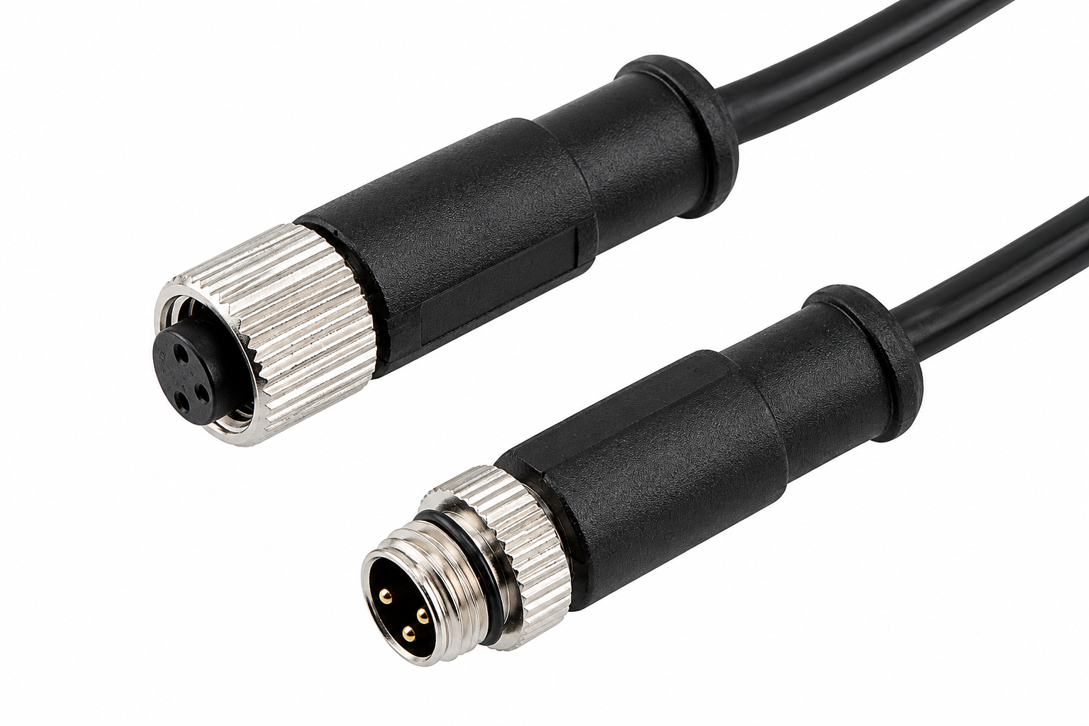
Custom Circular Connector Cable

Engineering-supported circular connector cable assemblies for industrial equipment, automation, sensors, outdoor systems, and long-term branded supply programs.

Cablivo supports circular connector cable projects from drawing, BOM, connector datasheet, device interface, or existing sample. Engineering review identifies missing specifications before a quotation or prototype plan is issued, reducing connector mismatch, wrong pinout, poor equipment fit, and sample-to-production variation.

  • Connector model, mating interface, pin count, orientation, and pinout reviewed before sampling.
  • M8 and M12 project directions, overmolded connector cables, and other circular connector models discussed against drawings or samples.
  • Cable length, AWG, conductor count, shielding, jacket material, overmold shape, and cable exit configured around the application.
  • Prototype validation, bulk production control, testing, labeling, packaging, and shipment coordination handled through one project workflow.

Circular Connector Cable Configurations for Different Equipment Interfaces

Circular connector projects range from compact sensor leads to molded equipment assemblies and replacement cables. The configuration should follow the mating interface, function, installation space, operating environment, and repeat-order plan rather than a generic connector photograph.

M8 Sensor Cables

M8 circular connector cables suit compact sensor, actuator, control, and device interfaces where installation space is limited. Development should begin with the exact connector model, pin count, gender, coding where applicable, and the mating receptacle. Cable length, AWG, conductor count, shielding, jacket, straight or angled exit, and labeling are then reviewed around the equipment. Cablivo treats M8 as an engineered assembly rather than a universal stock cordset, so availability, pinout, overmold construction, and required checks are confirmed before sampling.

  • Common direction: industrial sensors and compact automation equipment
  • Key files: connector model, pinout, interface photo, cable length
  • Optional discussions: shielding, overmold, label, packaging

M12 Sensor Cables

M12 circular connector cable assemblies are widely used around industrial sensing, automation, control, communication, outdoor equipment, and machine connections. A correct M12 description requires more than “M12 cable.” Pin count, gender, coding or keying where relevant, connector orientation, mating part, pinout, electrical function, cable OD, jacket, shielding, and environmental requirements all influence the design. Cablivo reviews the full specification before quoting, then develops a prototype plan that can include connector fit, electrical mapping, molded appearance, and production-file confirmation.

  • Common direction: sensors, actuators, control systems, equipment links
  • Key files: connector datasheet, mating interface, pinout, application
  • Optional discussions: PUR or other jacket direction, shielding, sealing structure

Single-Ended Assemblies

A single-ended circular connector cable uses a completed circular connector on one side and stripped wires, terminals, housings, ferrules, or another open-ended preparation on the opposite side. The open end must be defined through strip length, wire identification, terminal type, housing position, tinning, heat shrink, sleeve, or labeling requirements. These assemblies often connect field devices to control panels, equipment interiors, or custom electronic modules. Accurate production depends on drawings, pin mapping, wire colors, finished-end dimensions, and a clear inspection method for both the connector and open end.

  • End options: stripped, tinned, crimped, housed, labeled
  • Key risks: wire order, strip length, terminal mismatch, label error
  • Useful documents: drawing, pinout table, terminal model, sample photos

Double-Ended Assemblies

Double-ended assemblies connect two defined interfaces and may use circular connectors on both ends or a circular connector paired with another specified connector. Both mating systems, pin maps, cable function, shielding termination, cable length, and orientation must be reviewed together. A simple one-to-one wiring assumption can create serious functional errors when power, signal, ground, drain wire, or shell connections differ. Cablivo prepares the assembly around the final pin-to-pin relationship and can discuss labels, branch points, molded transitions, protective sleeves, and packaging for repeatable installation.

  • Configurations: circular-to-circular or circular-to-specified interface
  • Key checks: pin mapping, polarity, shell grounding, connector orientation
  • Project inputs: both datasheets, wiring table, length, quantity

Overmolded Circular Cables

Overmolding adds a controlled transition around the connector and cable, supporting connector protection, strain relief, sealing design, cable exit control, and consistent appearance. The molded structure should be developed around connector geometry, cable OD, installation clearance, material choice, hardness, logo position, color, surface finish, and tooling feasibility. A prototype is used to confirm connector fit, cable exit, molded dimensions, appearance, and any project-specific testing before bulk production. Cablivo’s injection-molding resources support molded and overmolded cable projects after tooling and sample requirements are confirmed.

  • Design inputs: overmold drawing, connector model, cable OD, exit direction
  • Visual inputs: color reference, logo file, surface requirement
  • Validation inputs: fit, pull force, sealing, appearance checklist

Custom Connector Projects

Some programs use Deutsch-style, proprietary, legacy, metal, plastic, push-pull, threaded, or another circular connector family. Cablivo can review specified circular connectors and custom connector directions against drawings, samples, connector models, device interfaces, and sourcing feasibility. The exact model, supplier, availability, mating part, terminal system, pin count, sealing parts, and assembly process must be confirmed before a prototype commitment. Alternative connector options may be discussed when the original model is unavailable, but substitutions are never treated as equivalent without engineering and project approval.

  • Start with: model number, datasheet, sample, or mating interface
  • Confirm: source, availability, terminal system, sealing parts
  • Avoid: brand-association claims or unapproved substitutions

Build an Accurate Circular Connector Cable Specification

A reliable quotation begins with the connector interface, electrical function, cable construction, operating environment, and expected quantity. Partial information is acceptable, yet every missing item should be identified before prototype production or final costing.

Specification Area

Information to Provide

Engineering Purpose

Connector family

M8, M12, Deutsch, another circular connector, or a specified model

Defines the mating system and sourcing route

Connector model

Part number, datasheet, supplier reference, or clear photos

Reduces model and component-selection errors

Mating interface

Mating part number, panel receptacle, device interface, or old assembly

Confirms mechanical compatibility

Gender and mounting

Male, female, cable mount, panel-side relationship

Prevents incorrect assembly direction

Pin configuration

Pin count, coding, keying, contact arrangement

Supports accurate connector and pinout review

Orientation

Straight, right-angle, left/right routing, cable exit direction

Protects installation clearance and cable routing

Pinout

Pin-to-wire map, polarity, grounding, signal allocation

Controls electrical function

Electrical requirement

Voltage, current, signal, communication, or mixed function

Guides AWG, conductor count, and test scope

Cable construction

Length, AWG, conductor count, OD, shielding, jacket

Defines material and process cost

Overmolding

Shape, dimensions, color, logo, hardness, strain relief

Sets tooling, appearance, and connector protection requirements

Operating environment

Movement, moisture, oil, abrasion, vibration, temperature, installation space

Guides material and validation discussions

Testing

Continuity, polarity, fit, pull force, sealing, or project-specific checks

Clarifies inspection responsibilities

Commercial details

Prototype need, MOQ, annual estimate, SKU plan, packaging, target schedule

Supports quantity planning and a workable quotation

Who Uses Custom Circular Connector Cable Assemblies

Circular connector assemblies serve teams that need controlled mechanical fit, electrical mapping, environmental protection, and repeatable production. Each group enters the project with a different risk, so specifications, proof, and quotation inputs should reflect the intended equipment and supply program.

Industrial Equipment Brands

Industrial equipment manufacturers need cable assemblies that fit fixed panel locations, machine enclosures, motors, controllers, sensors, and field devices. Connector model, orientation, mating interface, cable route, electrical function, strain relief, and service conditions are normally reviewed together. Procurement also needs approved specifications, stable component references, clear inspection items, packaging identification, and a repeat-order record. Cablivo supports the project from engineering files and samples through prototype approval and bulk manufacturing preparation.

Automation and Sensor Teams

Automation and sensor programs often use M8 or M12 circular connectors across sensing, actuation, control, and industrial communication. A small error in pin count, coding, wire map, shielding, or cable exit can stop commissioning. Engineering teams usually provide a datasheet, interface photo, pinout, cable length, equipment notes, and quantity. Cablivo reviews the assembly as a connected system, then aligns connector, cable construction, overmolding, testing, and labeling with the installation plan.

Robotics and Instruments

Robotics, instruments, and test equipment may require compact routing, frequent movement, controlled cable OD, shielding, clean labeling, or a connector exit that avoids mechanical interference. Material and bending expectations must be discussed against the actual motion and installation path rather than assumed from a generic cable type. Cablivo can review interface drawings, movement notes, cable route, connector orientation, and prototype feedback before finalizing production files and inspection points.

Outdoor Equipment Programs

Outdoor sensing, heavy equipment, vehicle electronics, marine-adjacent equipment, and exposed machinery may need connector protection, sealing discussions, abrasion-resistant jacket direction, overmolding, strain relief, or clear environmental testing requirements. Performance should never be inferred from appearance alone. Connector sealing parts, overmold structure, jacket selection, cable entry, installation stress, and validation method must be defined for the specific project before mass production.

Engineering Product Teams

Product and engineering teams may begin with a finished drawing, a partial BOM, an interface photograph, a legacy cable, or only an equipment concept. The main need is a structured route from incomplete information to a buildable sample. Cablivo reviews missing dimensions, connector and mating details, pinout, conductor requirements, material direction, overmold feasibility, testing, and production documents, helping the project move toward an approved sample without hiding unresolved assumptions.

Procurement Supply Teams

Procurement and supply teams evaluate more than unit price. They need connector-source clarity, MOQ, sample and bulk schedules, production-file control, test scope, packaging identification, shipment coordination, and repeat-order consistency. Cablivo’s project workflow connects engineering review with sourcing, sample development, production, quality, packaging, and export coordination. The resulting quotation is based on defined specifications and quantities rather than a single product photo or incomplete description.

Control the Main Risks Before Circular Cable Production

Circular connector cables fail for reasons that often begin before manufacturing: an unidentified mating interface, wrong pin map, incomplete installation data, unsuitable materials, unclear molded structure, or an unfrozen sample. Early review turns hidden assumptions into written specifications.

Connector Mismatch

Connectors can look similar while using a different shell size, keying, coding, pin arrangement, locking method, terminal system, or mating depth. A mistaken model can produce a well-made cable that cannot connect to the equipment. Cablivo reviews the connector part number, datasheet, mating part, gender, pin count, orientation, and interface photos before sampling. When the exact component is unavailable, any proposed alternative is documented for approval rather than silently substituted.

  • Risk: prototype cannot mate or lock correctly
  • Control: model, mating part, datasheet, and source review
  • Output: approved connector reference before build

Pinout Error

A correct connector does not guarantee correct function. Power, signal, ground, polarity, shield, drain wire, and shell termination may follow a project-specific map. One crossed wire can cause failed testing, equipment malfunction, field rework, or a full batch rejection. Cablivo uses a written pin-to-wire table, wire-color map, polarity requirement, and test checklist as production references. Unclear pins are returned for confirmation before sample wiring begins.

  • Risk: open, short, reversed polarity, or wrong signal
  • Control: approved pinout and wire-color mapping
  • Output: testable wiring definition

Wrong Exit Direction

A straight or angled connector may mate correctly but still interfere with a panel, enclosure, nearby component, operator path, or cable bend radius. Cable exit also affects mold design, strain concentration, routing, and visual alignment. Cablivo requests equipment interface photos, installation dimensions, insertion direction, and intended cable path. The selected orientation and exit are then included in drawings, sample review, and overmold confirmation.

  • Risk: assembly fits electrically but not mechanically
  • Control: installation-space and routing review
  • Output: confirmed connector and cable orientation

Unsuitable Cable Structure

AWG, conductor count, insulation, shielding, jacket, OD, flexibility, and protective layers must match electrical function and operating conditions. Choosing only by appearance can lead to excessive voltage drop, poor routing, interference, abrasion, stiffness, or connector-overmold incompatibility. Cablivo discusses cable construction around voltage, current, signal type, length, movement, installation space, environment, and cost direction. Final material and cable specifications are confirmed before mass production.

  • Risk: electrical or mechanical mismatch
  • Control: application-based cable structure review
  • Output: approved cable construction and material list

Weak Molded Transition

The cable-to-connector transition is a common stress area. An unsuitable overmold shape, material, hardness, cable exit, or strain relief can concentrate bending, reduce connector clearance, alter sealing geometry, or create inconsistent appearance. Cablivo reviews connector geometry, cable OD, overmold dimensions, tooling, logo, color, surface finish, and required validation. The molded sample becomes the appearance and structure reference for bulk production.

  • Risk: damaged transition or inconsistent molded head
  • Control: tooling and overmold sample approval
  • Output: defined molded structure and inspection points

Sample Bulk Drift

A functioning sample is not enough when the final drawing, BOM, connector source, pinout, material, molded appearance, labels, tests, and packaging remain unfrozen. Production can drift when verbal changes or old files are used. Cablivo links approved samples with final drawings, final BOM, production instructions, test requirements, and packaging files before bulk work begins. Any proposed material, connector, or packaging change requires discussion and confirmation.

  • Risk: bulk order differs from approved sample
  • Control: frozen files and approved references
  • Output: repeatable production baseline

Confirm the Connector Before Cable Development Begins

Connector selection controls mechanical fit, pin arrangement, terminal compatibility, sealing parts, orientation, overmold design, sourcing, and cost. A clear connector reference is the first protection against a prototype that looks correct but cannot operate in the intended equipment.

Model and Mating Interface

The strongest starting point is an exact connector part number supported by a datasheet and the mating part used in the equipment. When a part number is unavailable, clear photos of the connector face, shell, locking feature, cable exit, and equipment receptacle help narrow the review, but visual identification alone may not be enough. Pin count, keying, coding, gender, shell size, contact arrangement, mounting relationship, locking method, and mating depth can differ between visually similar circular connectors. Cablivo records the proposed connector model and asks for confirmation before sample production. The review should also identify whether the cable-side connector mates with a panel receptacle, inline connector, sensor, actuator, controller, motor, or another device. A sample of the mating interface is valuable when fit is difficult to establish from documents. For legacy replacement projects, the old cable and equipment-side connector should be compared together. When brand-name components are specified, model, source, availability, and permitted alternatives are handled as project requirements; no official brand relationship is implied.

  • Provide the cable-side connector model and mating connector model whenever available.
  • Include front, side, locking, and installed-interface photographs for unidentified parts.
  • Mark any non-negotiable brand, material, plating, or source requirement in the BOM.

Mechanical Configuration and Fit

Mechanical fit extends beyond the connector shell. Straight and right-angle constructions, left or right cable exit, panel clearance, cable OD, bend area, overmold dimensions, strain relief length, and insertion access all affect the finished assembly. A right-angle connector may need a specific clocking position relative to the keyway. A molded boot may interfere with a panel wall even when the connector itself mates correctly. Cable OD must also fit the connector, seal, gland, and mold structure. Cablivo requests interface dimensions, enclosure drawings, installation photographs, and cable routing notes when space is limited. The sample review should confirm mating, locking, orientation, exit direction, accessible installation, and the relationship between the connector and nearby components. Any dimension critical to installation is added to the drawing or inspection reference. Mechanical checks are discussed according to project requirements; a visual photograph alone cannot confirm a sealed interface, retention performance, or long-term bending behavior.

  • Show the connector in the installed position, including nearby walls and cable route.
  • State the required clocking, exit direction, and maximum permitted molded dimensions.
  • Identify any pull, vibration, movement, or repeated-mating expectation before sampling.

Source, Availability, and Alternatives

Connector availability influences quotation accuracy, prototype timing, MOQ, and bulk schedule. The required model may be a stocked industrial item, a special configuration, an imported part, a discontinued component, or a proprietary connector supplied by the project owner. Cablivo reviews the source path before committing to a sample plan. When the specified connector is supplied by the project owner, incoming inspection, quantity, spare allowance, packaging, and traceability expectations should be agreed. When Cablivo sources the component, the quotation should state the proposed model, source direction, and any commercial assumptions. If an original part is unavailable, an alternative can be evaluated only after mating, pin arrangement, material, electrical, sealing, and dimensional compatibility are reviewed. An alternative is not treated as a drop-in replacement merely because the shell appears similar. Final connector approval is documented before the assembly enters prototype or mass production.

  • Confirm who supplies the connector and how incoming parts are identified.
  • Review connector MOQ and availability before promising sample or bulk timing.
  • Approve every alternative model in writing before production use.

Define Pinout, Power, Signal, and Shielding Requirements

A circular connector assembly is defined by electrical mapping as much as mechanical fit. Pin numbers, wire colors, polarity, grounding, shield termination, and signal allocation must be written clearly enough for sample wiring, inspection, troubleshooting, and repeat production.

Mapping Item

Required Information

Why Confirmation Matters

Pin numbering

Connector-face numbering and viewing direction

Avoid mirrored or reversed interpretation

Wire color

Color assigned to every pin

Supports assembly and field identification

Wire function

Power, return, signal, communication, ground, spare

Defines conductor and test requirements

Voltage and current

Rated project values for each circuit

Guides AWG and material discussion

Polarity

Positive, negative, line, neutral, or direction-sensitive mapping

Prevents reversed-function failures

Signal/data

Protocol, frequency direction, pair relationship, or signal notes

Guides twisting, shielding, and test scope

Grounding

Protective ground, signal ground, chassis ground

Prevents ambiguous grounding practice

Shield termination

Connector shell, drain wire, one-end, both-end, or project-defined

Controls the approved shielding construction

Pairing/twisting

Which conductors form pairs or groups

Supports signal and harness construction

Shell connection

Connected, floating, or project-defined

Clarifies connector housing treatment

Continuity limits

Required pass/fail mapping and resistance criteria when specified

Creates a written electrical check

Open/short checks

Required circuits and acceptance method

Controls functional inspection before shipment

Select Cable Materials Around the Operating Environment

Cable construction should follow electrical function, length, movement, installation space, exposure, connector geometry, and cost direction. Materials are selected through project review and sample confirmation rather than a universal “best material” claim.

Conductor and Insulation

Conductor material, strand construction, AWG, conductor count, and insulation system shape current capacity, voltage drop, flexibility, outside diameter, termination method, and assembly cost. Copper and tinned-copper directions may be discussed according to the application and project specification. AWG should be reviewed together with cable length, operating current, connector contact capacity, temperature conditions, bundling, and installation constraints. A larger conductor is not automatically better when the connector, seal, mold, or equipment space limits cable OD. Insulation materials and thickness influence electrical separation, flexibility, diameter, stripping, soldering or crimping, and temperature discussion. For mixed power and signal assemblies, conductor groups may need different sizes or identification. Cablivo reviews the cable drawing, conductor table, electrical requirement, connector terminal range, and finished OD before confirming the cable structure. Final material descriptions belong in the BOM and approved sample record so bulk production does not rely on verbal descriptions.

  • State voltage, current, cable length, conductor count, and required AWG.
  • Confirm terminal range and connector cable-entry limits.
  • Record conductor and insulation materials in the final BOM.

Shielding and Grounding

Shielding may involve foil, braid, a combined structure, drain wire, twisted pairs, or no shield, depending on signal requirements, equipment design, environment, and cost. A shield is only useful when the termination method is defined. The project should state whether the shield connects to the circular connector shell, a drain wire, one end, both ends, chassis ground, or another approved point. Braid coverage, foil overlap, drain-wire size, pair construction, and jacket diameter can affect both performance and manufacturability, yet performance cannot be promised without a defined cable design and validation method. Cablivo can discuss shielding construction and termination against the pinout, connector structure, application notes, and test requirements. The approved wiring table and drawing should show grounding and shield termination clearly enough for production and electrical inspection. Unspecified shielding or shell connection should never be guessed during assembly.

  • Identify signal type, pair relationship, and interference concerns.
  • Mark shield and shell termination on the pinout or drawing.
  • Define any validation requirement before prototype production.

Jacket and Protective Layers

PVC, TPE, TPU, PUR, silicone, PE, XLPE, braided sleeve, protective sleeve, heat shrink, and other material directions may be discussed according to product type and operating needs. The jacket influences flexibility, abrasion behavior, appearance, chemical exposure discussion, cable OD, overmold bonding, and cost. PUR may be considered for industrial cable projects where abrasion, oil exposure, movement, or durability is important, but exact performance requires the final material grade and agreed test conditions. Protective sleeves can support routing, organization, and abrasion protection around machinery. Heat shrink and labels may identify branches, pin functions, or part numbers. Cablivo reviews the application, required color, tactile direction, movement, exposure, cable route, connector seal, overmold material, and packaging plan before confirming the construction. The sample should be used to assess handling, routing, appearance, and fit before bulk production.

  • Share environment, movement, routing, and appearance requirements.
  • Confirm jacket grade, color, OD, and overmold compatibility through the project record.
  • Use protective layers only where they solve a defined installation or handling need.

Overmolding Protects the Connector and Controls Cable Exit

Molded construction combines connector geometry, cable OD, material, tooling, exit direction, protection, sealing, and appearance. A successful mold begins with dimensional review and ends with an approved sample that can be repeated in bulk production.

Connector Protection

Overmolding covers the connector-to-cable transition and can provide a controlled protective structure around soldered, crimped, assembled, or potted areas. The mold must respect the connector locking feature, mating depth, keyway, seal, cable entry, and equipment clearance. Excess material can obstruct mating, while insufficient support can leave the transition exposed. Cablivo reviews connector dimensions, cable OD, internal assembly, mold split, overmold length, and finished-part access before tooling or sample production.
  • Confirm connector geometry and mating clearance
  • Define overmold dimensions and protected area
  • Use the approved molded sample as the bulk reference

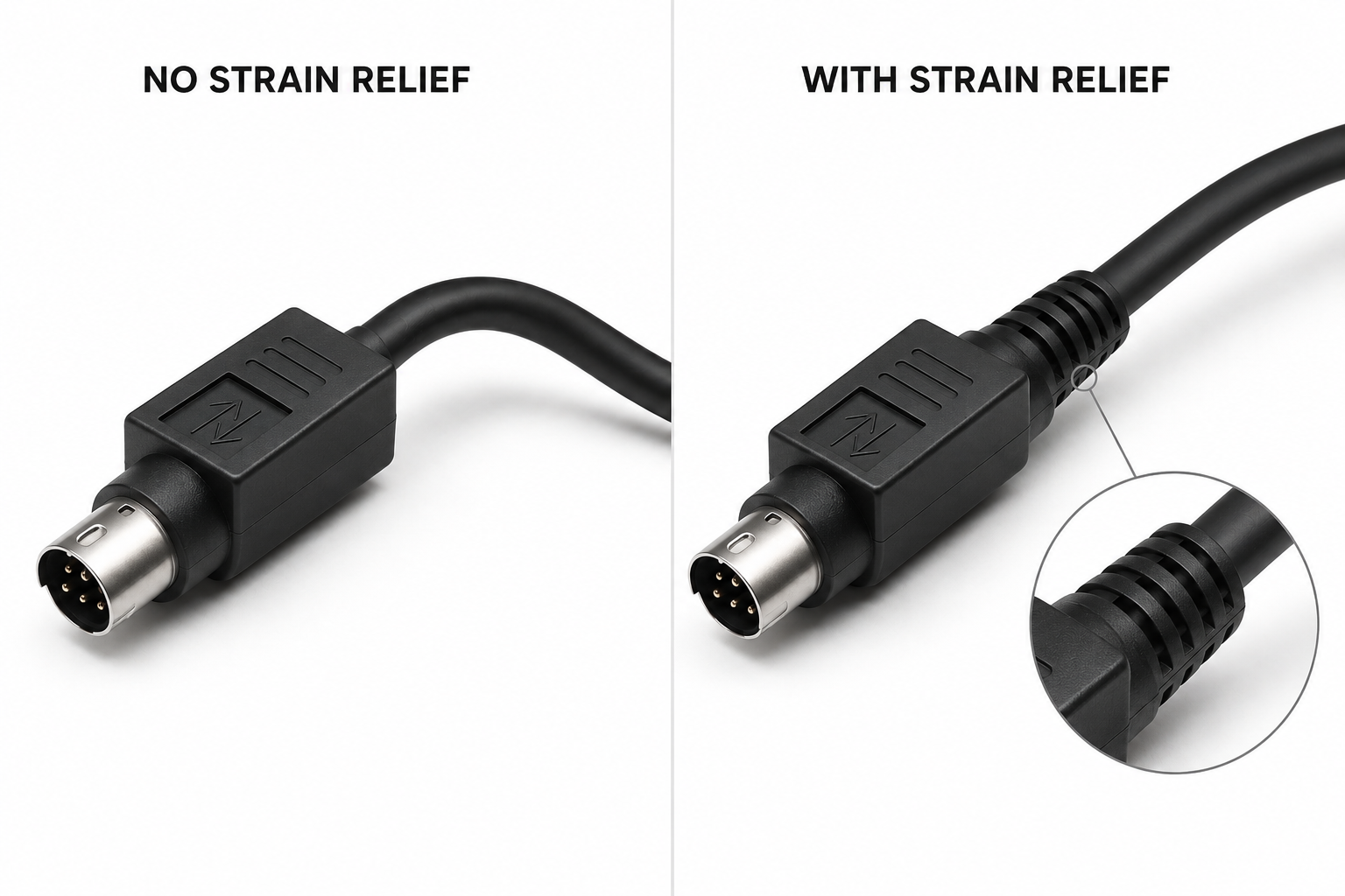
Strain Relief Design

Strain relief reduces concentrated stress where the cable leaves the connector or molded body. The geometry should follow cable OD, jacket flexibility, expected movement, bend direction, installation space, and handling. A long flexible relief may suit one assembly, while a compact boot may be needed in a confined enclosure. Cablivo discusses relief length, rib pattern, hardness, exit angle, transition thickness, and any pull or bending requirement. No fixed bending-life claim is made without a defined design and test method.

  • Share expected movement and load direction
  • Confirm exit angle, relief length, and material hardness
  • Define any pull or bending check before sampling

Sealing Structure

Waterproof or sealing performance depends on the complete interface: connector design, mating seal, O-ring or gasket, cable entry, overmold geometry, material, assembly, and validation method. A molded head alone does not guarantee a protection level. Cablivo reviews the connector and sealing structure, identifies the areas controlled by cable production, and discusses project-specific tests before bulk work. Any IP or leak-performance requirement should be supported by a defined connector system, assembly method, and acceptance procedure.

  • Provide the target environment and required protection level
  • Confirm mating connector, seal parts, and cable-entry structure
  • Agree on test method, sample quantity, and acceptance criteria

Molded Appearance

Molded appearance supports a consistent branded product through shape, color, logo position, surface finish, texture, part marking, and cable exit. The design must also remain manufacturable and compatible with the connector and cable. Cablivo can discuss custom mold shape, logo artwork, Pantone or reference color, hardness direction, surface treatment, and inspection samples. Appearance is approved through physical samples because digital renderings cannot fully represent material flow, gloss, texture, shrinkage, or the final transition.

  • Submit logo artwork, color reference, and surface direction
  • Confirm mold ownership, tooling revision, and approval process
  • Record appearance checkpoints for bulk inspection

Match Connector Orientation to Equipment Installation Space

Connector orientation affects mating access, enclosure clearance, cable routing, bend concentration, molded tooling, and serviceability. Direction should be confirmed from the installed equipment position rather than a product photo taken on a table.

Straight Cable Exit

A straight connector keeps the cable aligned with the connector axis and may offer a simple construction where rear clearance is available. The equipment still needs enough space for insertion, locking, strain relief, and the first cable bend. Cablivo reviews the panel position, connector length, molded length, cable OD, minimum routing space, and nearby components before the straight configuration is approved.

Right-Angle Exit

A right-angle construction redirects the cable close to the connector and can save rear space, but the angle must be clocked correctly relative to the keyway and equipment. A 90-degree exit can point up, down, left, or right after mating. Cablivo requests an installed-interface image or drawing so the connector orientation, molded body, cable route, and access to the locking mechanism can be confirmed.

Left or Right Routing

Some assemblies need a defined left or right route because the cable passes around a panel wall, motor, bracket, enclosure, or adjacent connector. Mirroring the direction can make an otherwise correct cable unusable. The drawing should show the viewing direction and installed position clearly. Cablivo includes the cable-exit reference in the sample check and production documentation to reduce orientation errors during repeat manufacturing.

Space-Limited Installation

Confined equipment may impose limits on connector body length, overmold width, boot length, cable OD, bend area, or the distance to a wall. Photos without dimensions rarely provide enough information. Cablivo asks for critical clearance dimensions, connector mating position, cable route, and installation sequence. A fit check or equipment-side sample may be required before tooling and bulk production are finalized.

Turn Drawings and Samples Into Production-Ready Specifications

Projects can begin from complete engineering files or from a small amount of evidence. The review process identifies what is known, what remains unresolved, and which decisions must be confirmed before quotation, tooling, sampling, or bulk production.

Starting Files and Evidence

A complete project package may include a drawing, BOM, connector datasheet, mating part, pinout table, cable specification, overmold drawing, test requirement, quantity, label artwork, and packaging file. Many projects begin with less. An old cable, connector photo, device interface, damaged assembly, sketch, wiring note, or application description can still support an initial review. Cablivo records every provided item and separates confirmed facts from assumptions. For a replacement cable, the old sample is compared for connector fit, pin layout, dimensions, wire colors, labels, molded geometry, and open-end preparation. For a new product, the equipment interface, electrical function, space, routing, and operating environment guide the first specification discussion. Partial information does not prevent communication, but unresolved connector, pinout, electrical, material, and fit details must be closed before production.

  • Useful files: drawing, BOM, datasheet, pinout, old sample, interface photos.
  • Commercial inputs: prototype need, quantity, SKU plan, packaging, target timing.
  • Confidential documents should be shared through the agreed project channel.

Engineering Review Actions

The review checks the connector model, mating interface, gender, pin count, orientation, cable exit, terminal system, pinout, voltage, current, signal allocation, wire gauge, conductor count, shielding, jacket, cable OD, overmold, strain relief, sealing, labels, tests, and packaging. Missing dimensions or conflicting files are listed for clarification. The proposed cable construction is compared with connector entry limits and equipment space. Overmold feasibility is discussed against connector geometry, cable OD, mold shape, logo, color, material, and tooling. Connector sourcing and availability are reviewed before a sample schedule is offered. Testing requirements are separated into electrical, mechanical, fit, appearance, and packaging checks. Every answer is tied back to a drawing, BOM, approved note, or sample record so engineering and production work from the same information.

  • Conflicts between drawing, sample, BOM, and pinout are resolved before build.
  • Connector and material alternatives are submitted for approval, never assumed.
  • Inspection points are defined while the specification is being finalized.

Review Output and Next Step

A useful review produces a clear next action rather than a generic “quotation available” message. The output may be a missing-information list, a proposed specification summary, connector and cable options, a tooling discussion, a preliminary BOM direction, a prototype plan, or a quotation based on stated assumptions. When the project is ready for sampling, the approved input set should identify the connector, mating interface, pinout, cable structure, length, orientation, molded requirements, tests, label, packaging, and prototype quantity. A prototype schedule is issued after connector availability, tooling, material, and validation scope are understood. Bulk timing is quoted separately after sample approval, final files, production quantity, and packaging are confirmed. The result is a controlled path from technical information to a sample that can become a production reference.

  • Engineering review may begin before every detail is complete.
  • Sampling begins only after critical connector, pinout, and construction items are confirmed.
  • Bulk planning begins after approved sample and production-ready files.

From Project Files to an Approved Cable Sample

Prototype work converts drawings, samples, connector details, and application requirements into a physical assembly for fit, function, appearance, and manufacturing review. The schedule is confirmed after connector availability, material, tooling, and required validation are understood.

Files Received

Cablivo records the drawing, BOM, connector model, mating interface, pinout, cable specification, sample photos, application notes, quantity, test requirements, and packaging information. Missing documents are listed rather than replaced by assumptions. A clear project record helps engineering, sourcing, sampling, quality, and production work from the same information.

Requirements Reviewed

Engineering checks connector fit, pin count, orientation, cable exit, terminal range, pinout, electrical function, AWG, conductor count, shielding, jacket, cable OD, overmold, strain relief, sealing, labels, and tests. Conflicts between drawings, samples, BOM files, or verbal notes are returned for confirmation before material preparation.

Prototype Prepared

Materials and connectors are prepared according to the approved sample specification. The assembly may involve cutting, stripping, crimping, soldering, connector assembly, potting, heat shrink, labeling, injection overmolding, or other agreed processes. Prototype quantity and construction depend on project complexity, tooling, validation, and the need for internal or external review.

Fit Function Check

The prototype is checked against the agreed requirements. Review may include connector mating, locking, orientation, cable exit, pinout, polarity, continuity, open and short circuits, cable length, appearance, overmold dimensions, label position, and packaging. Additional checks are discussed according to the product and project requirement rather than treated as universal defaults.

Revision Managed

Feedback is recorded by issue, required change, reason, file version, and responsible confirmation. Revisions may involve connector model, pinout, length, wire gauge, material, cable exit, overmold shape, color, logo, label, or packaging. Updated samples should be linked to updated drawings and BOM files so an old version is not used during bulk production.

Sample Approved

Approval confirms the physical sample and the supporting specifications that will guide production. The approved set may include the sample, final drawing, final BOM, connector reference, pinout, color and appearance notes, test checklist, labels, and packaging files. Sample approval marks the beginning of production control, not the end of engineering responsibility.

Protect Sample Approval During Bulk Cable Production

Bulk consistency depends on frozen specifications, controlled components, documented processes, and inspection points. The approved sample becomes useful only when every production team can trace it to the final drawing, BOM, pinout, material, molded appearance, labels, tests, and packaging.

Freeze Final Specifications

Before bulk production, the project record should identify the approved sample version, final drawing, final BOM, connector model and source, terminal or contact, pinout, wire-color map, cable construction, length, orientation, cable exit, overmold drawing, material, color, logo, labels, tests, packaging, SKU list, and carton marking. Any discrepancy between sample and files must be resolved. Verbal approval is not enough for a complex connector assembly because the sample alone may not reveal internal conductor size, shield termination, component source, or production test settings. Cablivo organizes the final references so sourcing, production, quality, packaging, and repeat-order teams can use the same version. When a specified component becomes unavailable, a proposed change is returned for written approval before production. Bulk lead time is confirmed after final files, approved sample, connector and material status, quantity, test scope, and packaging are reviewed.

  • Final drawing and BOM should carry matching revision references.
  • Approved sample photos help preserve orientation, mold, color, and label placement.
  • Any component or packaging change requires confirmation before use.

Control Materials and Process

Material preparation includes the cable, connector, contacts, terminals, seals, housings, overmold material, heat shrink, sleeves, labels, and packaging components defined by the final BOM. Production steps may include cutting, stripping, crimping, soldering, connector assembly, potting, overmolding, heat shrink, labeling, electrical testing, appearance checks, and packaging. Each step controls a different risk: cut length protects finished dimensions; stripping protects conductor integrity; crimping or soldering protects electrical connection; connector assembly protects pin position and locking; overmolding protects geometry and appearance; testing protects electrical mapping; packaging protects SKU and identification. Cablivo aligns process instructions and inspection points with the approved sample and files instead of relying on broad claims about strict quality.

  • Incoming materials are checked against approved references and project requirements.
  • In-process checks focus on dimensions, wire preparation, pin position, orientation, and molded appearance.
  • Finished checks follow the approved electrical, mechanical, appearance, and packaging scope.

Build Repeatable Orders

Long-term supply requires records that survive beyond the first shipment. Part numbers, revision history, connector source, pinout, cable construction, sample approval, test checklist, label artwork, packaging version, SKU list, carton mark, and shipment batch should be traceable. Repeat orders are reviewed against the last approved version and any requested change is recorded before material preparation. Multi-SKU programs need a clear quantity breakdown by connector, length, color, label, and packaging version to reduce mixed packing or wrong identification. Cablivo’s cross-functional structure connects engineering, sourcing, production, quality, warehousing, packaging, sales coordination, and shipment preparation, supporting a controlled route from the first approved sample to future orders.

  • Use one controlled specification set for every repeat order.
  • Separate quantities and packaging by SKU before production release.
  • Record approved changes so later orders do not return to an obsolete version.

Production Process for Power Cable Assemblies

Power cable production may include cutting, stripping, crimping, soldering, overmolding, assembly, testing, labeling and packaging, depending on cable structure.

Typical production flow:

Material and connector preparation
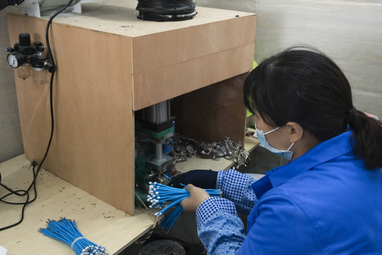
Cable cutting and stripping
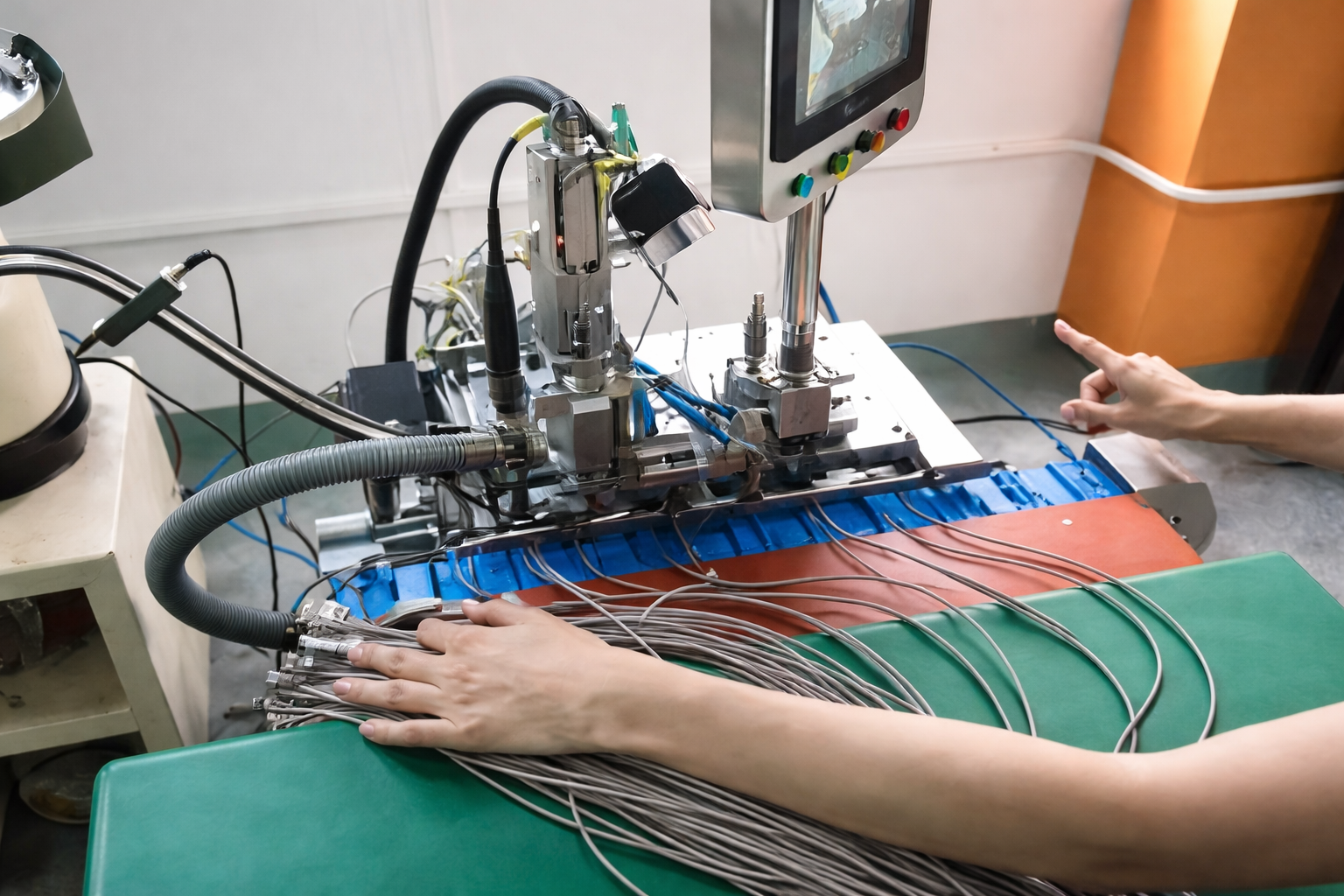
Terminal crimping or soldering

Injection Molding / Connector Assembly
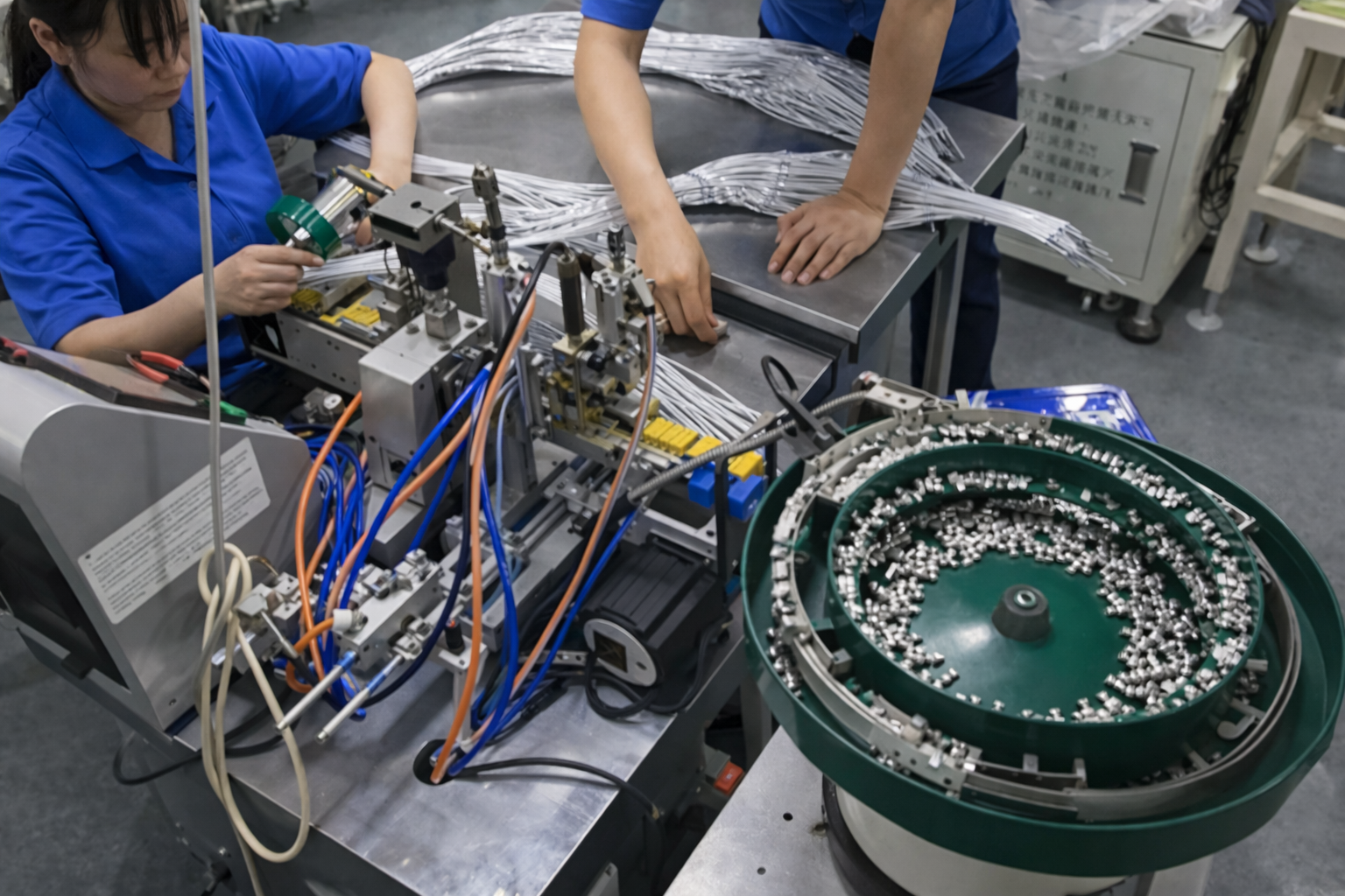
Connector assembly
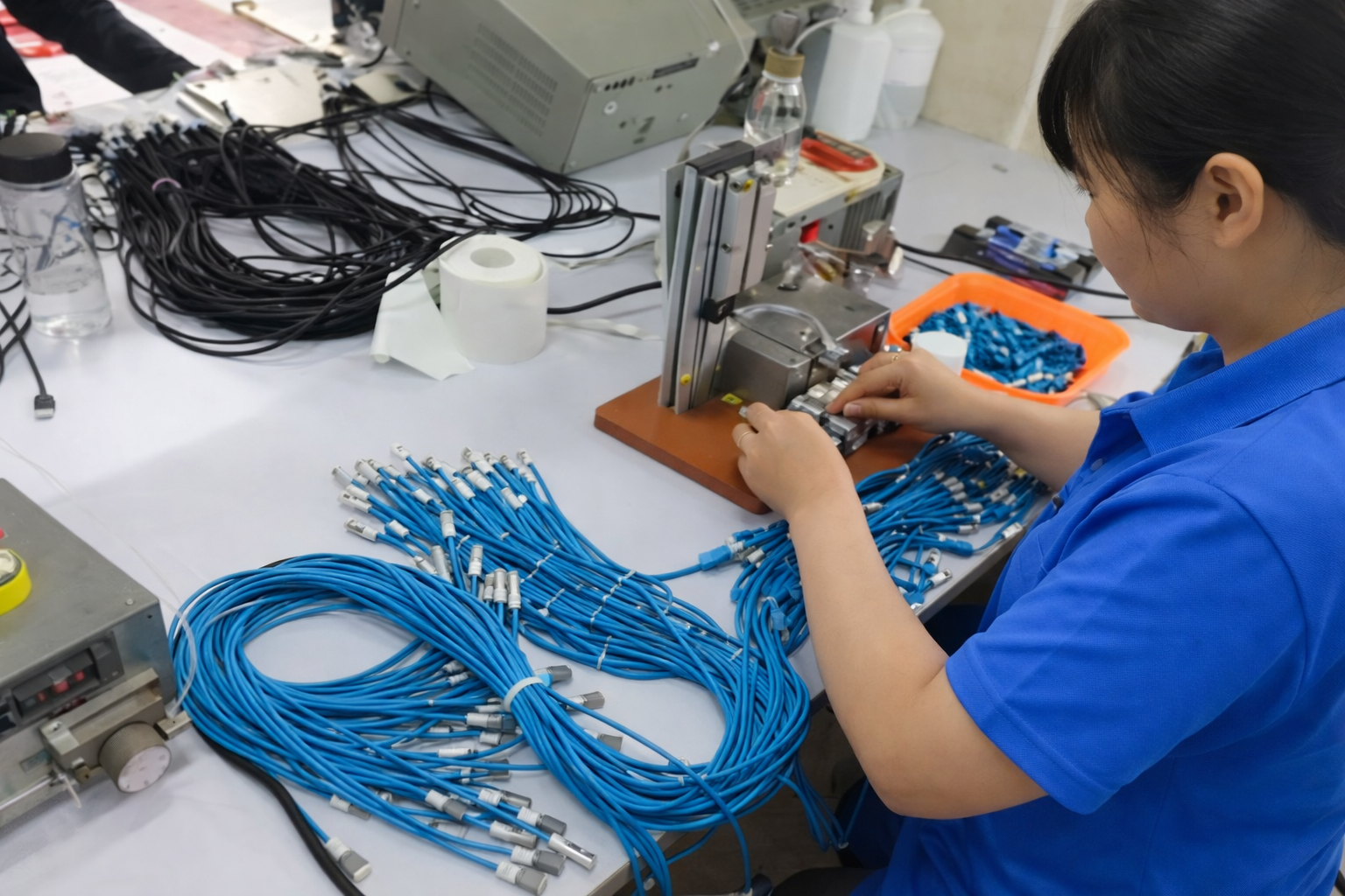
Sleeve, heat shrink or overmold processing

Continuity, polarity or fit check
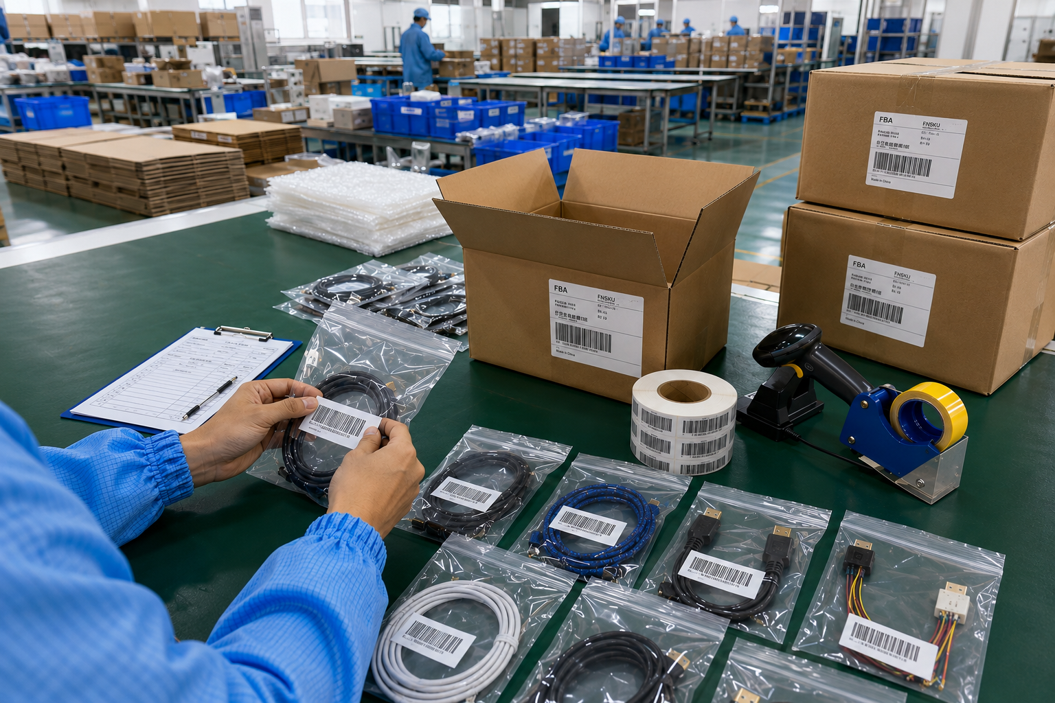
Appearance and label inspection

Packing, carton mark and shipment preparation

Build Testing Around Product Function and Project Risk

Testing should follow the connector, cable construction, electrical function, environment, approved sample, and project requirement. The matrix below shows review directions, not a promise that every item applies to every circular connector cable assembly.

Category

Possible Check

Purpose

Confirmation Basis

Electrical

Continuity and pin-to-pin mapping

Confirms every circuit follows the approved pinout

Pinout and test checklist

Electrical

Polarity

Checks direction-sensitive power or signal mapping

Approved wiring table

Electrical

Open and short circuit

Identifies broken or unintended connections

Project test requirement

Electrical

Resistance or hi-pot when specified

Supports defined electrical acceptance criteria

Product specification and agreed method

Mechanical/Fit

Connector mating and locking

Confirms interface engagement and operation

Mating connector or equipment interface

Mechanical/Fit

Cable length and finished dimensions

Confirms installation fit

Drawing and approved sample

Mechanical/Fit

Pull force when specified

Reviews terminal or molded transition retention

Defined location, load, and method

Mechanical/Fit

Bending or movement when specified

Evaluates an agreed construction under stated conditions

Defined cycle, radius, load, and acceptance

Appearance

Connector orientation and cable exit

Confirms installed direction

Drawing and sample

Appearance

Overmold, color, logo, surface

Controls branded appearance and clearance

Approved molded sample and artwork

Identification

Wire labels, part number, barcode, SKU

Supports installation, warehouse, and repeat orders

Label and SKU files

Packaging

Packing quantity, bag or box, carton mark

Prevents mixed versions and shipment errors

Approved packaging file

Label and Pack Every Circular Cable Version Clearly

Packaging is part of specification control when a program includes several connector models, lengths, pinouts, labels, or destinations. Clear identification protects warehouse handling, installation, distribution, repeat orders, and shipment preparation.

Cable Identification

Cable labels can carry a part number, drawing revision, length, wire function, equipment position, serial or batch reference, or other approved information. Label material, size, position, print direction, and content should be defined before bulk production. For harness-style or open-ended assemblies, wire markers can support installation and service. Cablivo checks label files and position against the approved sample or packaging instruction.

Barcode and SKU

Multi-SKU programs may differ by connector, pinout, length, color, jacket, overmold, label, packaging, or destination. A quantity breakdown and unique SKU reference reduce mixing during production and packing. Barcode type, data, artwork, print size, placement, and scan requirement should be provided by the brand or procurement team. Cablivo aligns product labels, inner packaging, cartons, and packing lists with the approved SKU structure.

Product Packaging

Packaging may use bags, protective caps, cable ties, coils, trays, inserts, boxes, or project-specific materials. The method should protect connector faces, molded surfaces, cable shape, labels, and required presentation while remaining efficient for transport and warehouse handling. Sample packaging can be reviewed before bulk production when appearance, retail presentation, or installation kits are important. Final material, artwork, packing quantity, and sealing method belong in the packaging file.

Carton Shipment Files

Carton marks, carton size, gross and net weight, packing quantity, SKU allocation, packing list, and forwarder details support export and warehouse processing. Multi-SKU cartons should follow a clear allocation rule. Cablivo coordinates carton and shipment information after the final quantity and packaging plan are confirmed. No customs, platform, or delivery result is guaranteed; manufacturing-side documents and packing details are prepared according to the agreed project scope.

Manufacturing Resources Behind Circular Connector Cable Projects

Cablivo combines engineering review, sample development, cable processing, connector assembly, injection overmolding, testing, packaging, and shipment coordination. Company scale matters only when each resource is connected to a visible project result.

18 Years Experience

Eighteen years in the cable industry provide long-term exposure to drawings, samples, connectors, BOM files, pinouts, materials, tooling, testing, packaging, and export coordination. Experience is used to identify missing information before it becomes a sample or bulk-production problem. Cablivo focuses on project-based custom cables, wire harnesses, cable assemblies, molded cables, industrial cables, power cables, communication cables, and related programs rather than low-price standard-cable selling.

20,000+ m² Factory

More than 20,000 square meters of factory space provide the physical foundation for multi-category cable manufacturing, material preparation, wire processing, connector assembly, injection molding, testing, packaging, warehousing, and shipment preparation. Floor area is not presented as a stand-alone achievement; it supports parallel projects, organized production zones, sample and material control, packaging work, and capacity planning for custom cable, wire harness, cable assembly, and molded cable programs.

1,500+ Person Team

A team of more than 1,500 people supports engineering, quality, sales coordination, procurement, warehousing, production management, manufacturing, packaging, shipment, and operational functions. Circular connector cable projects require coordination across connector sourcing, pinout review, wire processing, molding, testing, labels, and packing. The team structure allows project information to move through defined responsibilities instead of depending on a single sales contact. Staffing may change over time, while the project value remains cross-functional coordination.

3 Manufacturing Bases

Three manufacturing bases strengthen order acceptance, production coordination, multi-project handling, and supply planning across the company. The relevant production route depends on product type, connector, cable construction, process, tooling, quantity, test scope, packaging, and schedule. Manufacturing-base information should never be used to imply that every process is available at every location or that delivery is guaranteed. The benefit lies in a broader organizational foundation for long-term and multi-category cable programs.

80+ Injection Machines

More than 80 injection molding machines support the company’s molded and overmolded cable manufacturing foundation. Equipment types include vertical and servo-assisted injection systems suited to connector protection, cable overmolding, strain relief, molded structures, and appearance-controlled parts. Machine count does not replace tooling, material, process, and sample approval. Each circular connector overmold still requires connector geometry, cable OD, exit direction, mold design, material, color, logo, surface, and inspection criteria to be confirmed.

Full Project Coordination

Cablivo supports the path from requirement review, drawing and BOM review, connector confirmation, material discussion, prototype development, sample revision, and sample approval to bulk production, quality inspection, packaging, labels, and shipment coordination. The service model is designed for overseas brands, engineering teams, procurement teams, industrial manufacturers, distributors, importers, and long-term supply programs. The goal is not to promise every connector or test, but to define the project clearly and manage confirmed requirements through production.

See How Circular Connector Cable Projects Are Documented

Strong project evidence comes from traceable engineering, sample, production, testing, and packaging records. Cablivo uses approved, non-confidential materials to show how a circular connector cable requirement moves through review and manufacturing without relying on generic testimonials or invented performance claims.

Engineering Evidence

Engineering evidence may include a redacted drawing, connector datasheet, mating-interface photograph, pinout table, BOM excerpt, cable-construction diagram, overmold sketch, missing-information list, or revision record. The purpose is to show how specifications are clarified before a sample is built. A useful project summary explains the starting information, the unresolved risk, the engineering action, and the approved output. For example, the project may need connector-model confirmation, pin-map correction, cable-exit adjustment, material discussion, or overmold dimensional review. Client identity, confidential device details, proprietary pinouts, and commercial information are removed unless disclosure has been authorized. When no publishable project record exists, a generic engineering demonstration should be labeled as a capability example rather than presented as a completed client case.

  • Show the review action, not only the submitted file.
  • Use redaction and approval before publishing technical material.
  • Separate real project evidence from generic capability demonstrations.

Sample and Production Evidence

Sample evidence can show connector identification, first assembly, fit review, cable exit, molded structure, label position, prototype comparison, revision notes, and the approved-sample reference. Production evidence can show cable preparation, stripping, crimping or soldering, connector assembly, overmolding, in-process inspection, and finished-part comparison. The strongest visual sequence links every stage to an identified risk: connector face to mating accuracy, pin table to electrical mapping, molded sample to cable exit and appearance, production file to bulk consistency. Images should avoid confidential brand marks, serial numbers, drawings, or unapproved client products. A completed sample does not prove production consistency by itself, so approved files and process checkpoints should appear alongside the finished assembly.

  • Use close-ups that reveal connector, pin, mold, label, and process details.
  • Pair sample photographs with the approved revision or inspection point.
  • Do not publish unapproved client products or logos.

Testing and Packaging Evidence

Testing evidence may show continuity or pinout equipment, mating checks, dimensional inspection, appearance review, label verification, or packaging inspection according to the project scope. Packaging evidence may include approved bags or boxes, protective caps, cable coils, labels, barcodes, SKU separation, packing quantity, carton marks, and shipment preparation. Published content should explain what was checked and why it mattered without claiming a universal pass rate, guaranteed performance, or certifications not supported by records. An anonymized project summary can state that a sample was used to confirm connector fit and molded appearance, while sealing or environmental performance remained subject to the defined connector system and test method. Such boundaries increase credibility and help engineering and procurement teams understand the information needed for a similar project.

  • Name the inspection purpose and project requirement.
  • Avoid invented test values, client praise, and commercial outcomes.
  • End every evidence section with a clear list of files for a similar project.

Why Customers Trust Tianxiaowei

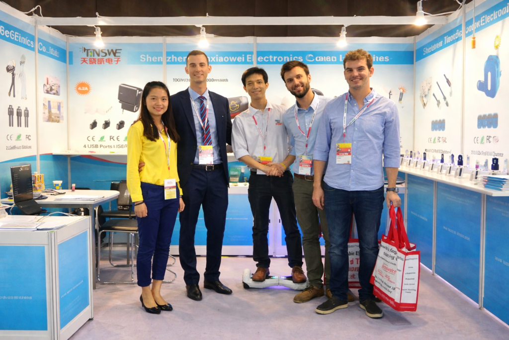
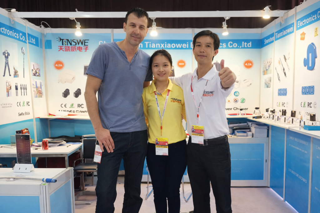
Real customer feedback and cooperation moments that reflect our product quality, responsive service, and
long-term manufacturing support.

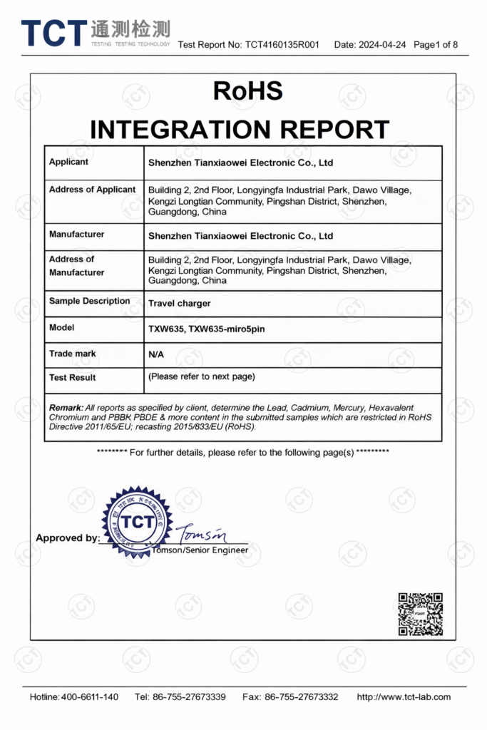
Certificates & material control

Custom Circular Cable Frequently Asked Questions

Review the main specification, sampling, MOQ, timing, material, overmolding, sealing, testing, and production questions before sending drawings, samples, connector photos, or a pinout table.

What information is needed for a quotation?

Provide the connector model or photos, mating interface, pin count, orientation, pinout, cable length, AWG, conductor count, electrical function, shielding, jacket, overmold, operating environment, testing, quantity, and packaging. Partial information is acceptable for an initial review, but critical connector and pinout details must be confirmed before sampling.

Yes. An existing cable can support connector identification, dimensions, pinout comparison, wire colors, molded shape, labels, and packaging review. Send clear photographs and, where possible, the physical sample and mating interface. Hidden materials and internal wiring still require confirmation through documents, inspection, or agreed assumptions.

Cablivo supports M8 and M12 project directions and can review Deutsch-style, custom, legacy, and other circular connector models according to drawings, samples, sourcing, and application requirements. Availability is confirmed before sampling. Unconfirmed M16, M23, or other families are not presented as standard stock capability.

Yes. Pin-to-wire mapping, wire colors, polarity, grounding, shield termination, and function can follow an approved project table. The viewing direction and pin numbering must be clear to avoid mirrored wiring. Final pinout and test references are confirmed before prototype and bulk production.

Straight, right-angle, and project-specific cable-exit directions can be discussed. Equipment interface, keyway position, installed clocking, available space, cable route, connector dimensions, overmold size, and locking access should be provided. A fit review or physical interface may be needed before tooling approval.

Material directions may include copper or tinned copper, PVC, TPE, TPU, PUR, silicone, PE, XLPE, foil shielding, braided shielding, protective sleeve, and heat shrink according to product needs. Final material grades and construction depend on electrical function, environment, movement, connector limits, cable OD, validation, and cost.

Yes. Mold shape, dimensions, cable exit, strain relief, material, hardness, color, logo, and surface direction can be discussed around the connector and cable. Tooling feasibility and sample approval are required. No fixed bending-life or protection claim is made without an agreed construction and test method.

Sealing depends on the connector, mating interface, seals, cable entry, overmold, material, assembly, and defined test method. A molded head alone does not guarantee an IP level. Share the target environment, protection requirement, mating connector, and acceptance method before sampling.

MOQ starts from 500 pieces for many custom cable projects. Final MOQ depends on connector availability, cable construction, material, overmolding, tooling, color, labels, packaging, SKU quantity, and total order volume. Prototype quantity and bulk MOQ are reviewed separately.

A prototype schedule is confirmed after connector availability, cable material, tooling, overmolding, and test scope are reviewed. Bulk lead time is confirmed after sample approval, final drawing and BOM, quantity, component status, testing, labels, and packaging are finalized. Separate schedules prevent an early estimate from ignoring unresolved project requirements.

Send Your Circular Connector Cable Requirements

Share the information already available, even when the specification is not complete. A drawing, BOM, connector model, datasheet, mating-interface photograph, pinout table, existing sample, or application note can start the engineering review. Include cable length, AWG, conductor count, voltage or current, signal function, shielding, jacket, connector orientation, cable exit, overmolding, strain relief, sealing requirement, testing, target quantity, packaging, and intended schedule where known. Cablivo will separate confirmed details from missing items, review connector and material feasibility, and identify the next step for quotation or prototype development. MOQ starts from 500 pieces for many custom cable projects, while the final quantity requirement depends on connector, material, tooling, overmolding, packaging, and SKU structure. Prototype and bulk schedules are issued after the relevant technical files, component availability, validation scope, approved sample, quantity, and packaging plan are confirmed. Confidential drawings and samples should be uploaded through the agreed project channel. Clear files help shorten review loops and improve quotation accuracy.

Send inquiry

Send your drawing / sample photos for a quick quote

Seraphinite AcceleratorOptimized by Seraphinite Accelerator
Turns on site high speed to be attractive for people and search engines.