 Skip to content


Ordering an M8 male cable assembly can look simple at first. A request such as “M8 male, two meters, 1,000 pieces” sounds specific enough to start pricing, yet it leaves many engineering questions unanswered. The connector may use the wrong contact arrangement, the mating interface may not be confirmed, the cable may need shielding, the jacket may need to handle a harsher environment, or the right-angle exit may point in the wrong direction once installed. Each missing detail can change component sourcing, cable construction, tooling, testing, production method and final cost.
To quote an M8 male cable assembly accurately, a manufacturer normally needs the exact M8 connector configuration, pin count and mating information, cable length, conductor size, core count, pinout, shielding, jacket material, application environment, protection requirements, testing criteria, target quantity, drawing or sample reference, packaging requirements and any special labeling or tooling information. A quotation becomes much more useful when these inputs are confirmed before assumptions enter the project.
The important point is not to create the longest possible RFQ. The goal is to provide enough controlled information that engineering, sourcing, production and quality teams are all discussing the same finished product. Two cable assemblies can look almost identical from the outside yet differ electrically, mechanically or environmentally in ways that only appear during installation or testing. That is often where an apparently inexpensive sourcing decision becomes expensive. A well-prepared RFQ helps identify those differences before the first sample is built.
What M8 Male Connector Details Are Needed?
An accurate M8 male cable quotation needs the exact contact count, coding or keying, connector orientation, mating interface, opposite-end termination and any approved connector part number. “M8 male” identifies only the connector family. It does not fully define the mating geometry, pin arrangement, component sourcing, overmold structure, sealing requirement or finished cable configuration that must be manufactured.
The current IEC 61076-2-104 specification covers M8 circular connectors used for signal and power connections in automation equipment, including a range of contact arrangements rather than one single universal configuration. Commercial M8 product families also differ in pin count, coding, straight or angled orientation, material, shielding, locking method and intended application. For quotation purposes, the mating equipment should therefore be treated as the starting point. A device part number, connector drawing or clear front-face photograph can eliminate far more uncertainty than the generic phrase “standard M8.”
| Connector Item | Common Project Variation | What the RFQ Should State | Quotation Risk if Missing |
| Contact count | 3, 4, 5 and other M8 arrangements exist | Exact pin count | Wrong connector or wiring structure |
| Coding/keying | Application-dependent | Exact coding or mating reference | Connector may not mate |
| Gender | Male specified for this project | Confirm mating-side gender | Wrong interface combination |
| Orientation | Straight or right-angle | Required cable exit direction | Installation interference |
| Locking | M8 locking interface varies by product family | Device or mating connector reference | Mechanical mismatch |
| Other end | Pigtail, M8 female, M12, terminal or custom end | Define complete assembly | Incomplete BOM and labor estimate |
| Connector source | Customer-selected or supplier-selected | Part number or equivalent policy | Sourcing uncertainty |
| Overmold | Standard or custom | Shape, material, sealing and tooling needs | Tooling cost may be omitted |
Which Pin Count and Coding Are Required?
Pin count should be confirmed from the mating device rather than guessed from what is common in a supplier’s catalog. M8 systems appear in sensor, actuator, industrial data and compact automation connections, and different product families use different contact arrangements. If an existing sensor, actuator, encoder, I/O block or control unit is already selected, its datasheet or mating connector part number should be included in the RFQ. That gives the cable manufacturer a controlled reference for contact count, mechanical interface and electrical assignment.
Coding or keying requires the same care. An A-coded sensor-style interface and another M8 coding cannot be assumed interchangeable simply because the outside connector diameter looks similar. The front-face geometry and key position matter mechanically, while the pin arrangement matters electrically. When the exact coding is uncertain, a clear front-view photograph combined with the mating component number is far safer than writing “normal M8 connector.” For replacement projects, sending the old sample or mating receptacle can be especially useful when historical documentation is incomplete.
Is the Connector Straight or Right-Angle?
Connector orientation often depends on the available installation space rather than personal preference. A straight M8 connector can work well where the cable exits directly away from a sensor or machine panel, while a right-angle connector may be necessary where a cabinet wall, sensor bracket, machine frame or nearby component limits axial clearance. The selected orientation therefore affects both product fit and the shape of the molded connector area.
For right-angle molded assemblies, the cable exit direction should ideally be indexed relative to the connector keying or another fixed reference. Without that information, a supplier can produce an electrically correct cable whose outlet points toward a machine wall instead of along the intended routing path. Drawings are particularly valuable here because they can show the connector face, key position and cable outlet in one view. During sample review, the connector should be physically checked against the actual equipment whenever installation clearance is critical.
What Is the Other-End Termination?
The second end of the cable can change the project as much as the M8 connector itself. One assembly may terminate in stripped conductors for direct wiring into a cabinet, another may use an M8 female connector, another may convert to M12, and another may require terminals, ferrules, a proprietary connector or a branch into a larger harness. These configurations use different components, processes and inspection methods even if End A remains the same M8 male connector.
If the opposite side is an open pigtail, specify strip length, conductor preparation, ferrules, tinning, terminals, heat-shrink tubing and labels where required. If it uses another connector, provide that connector’s model, gender, orientation, pinout and mating information as well. The finished cable assembly should be quoted as one complete product rather than as an M8 connector plus an undefined length of wire. This avoids additional charges or engineering changes appearing after the initial quotation.
Which Connector Part Number Is Used?
An approved connector part number is one of the strongest pieces of information in a cable RFQ because it allows engineering and sourcing teams to verify mating geometry, contact count, terminal method, material, electrical rating, protection level and availability before the quote is finalized. If the original manufacturer and part number are mandatory, the RFQ should make that restriction clear rather than allowing an unapproved alternative to enter the BOM.
When an equivalent connector may be accepted, define which characteristics are non-negotiable. These might include mating dimensions, coding, IP requirement, pin configuration, contact plating, operating environment or required documentation. If no part number exists, useful alternatives include the mating device datasheet, dimensional drawing, connector photographs and an original physical sample. Connector availability should be checked before sampling, and any proposed equivalent should be confirmed before it becomes part of the production specification.
Which Cable Specifications Affect the Quote?
Cable length, conductor size, core count, cable diameter, shielding, jacket material, flexibility and environmental requirements can all change the finished M8 assembly and its cost. The cable should therefore be treated as an engineered part of the product rather than described simply as “two meters of black cable.” Even when the connector remains unchanged, different cable structures can require different materials and manufacturing processes.
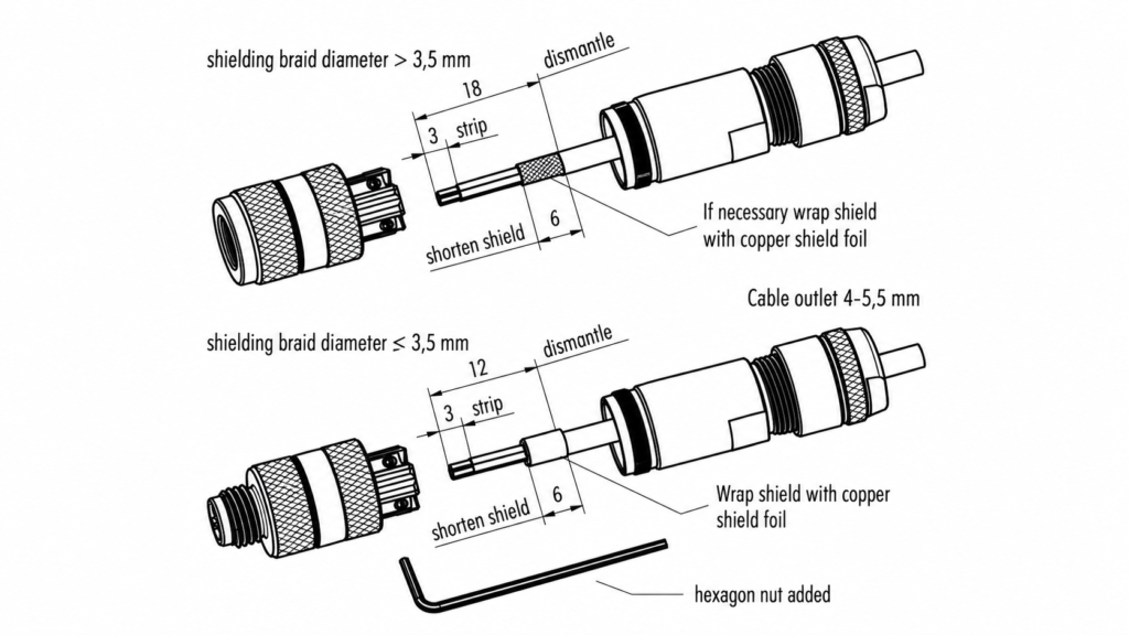
Commercial M8 product families show why cable definition matters. Industrial M8 assemblies are available with PVC or PUR jackets, shielded or unshielded construction, multiple conductor counts and different cable diameters. Some connector designs accept only a defined range of cable outside diameters because the sealing and strain-relief structure depends on cable size. These catalogue values are useful references, but a custom assembly still needs its own specification based on electrical load, installation conditions, movement and target-market requirements.
| Cable Variable | Useful RFQ Input | Typical Decision Value | Effect on Quotation |
| Finished length | Defined measurement and tolerance | Millimeters or meters | Copper, jacket, cutting and packaging |
| Conductors | Exact core count | Must match circuit design | Cable structure and termination |
| Wire gauge | AWG or mm² | Based on current and application | Copper cost and cable diameter |
| Cable OD | Actual or allowable range | Connector-specific | Sealing and strain relief |
| Shielding | None, foil, braid or combined | Based on EMC needs | Material and termination labor |
| Jacket | PVC, PUR or specified material | Based on application | Material cost and durability |
| Movement | Static or repeated movement | Application-dependent | Flexibility and conductor choice |
| Marking/color | Standard or custom | Project-defined | Material sourcing and identification |
What Cable Length and Tolerance Are Required?
Cable length should be defined using clear measurement points. “Two meters” can mean jacket length, connector-face-to-free-end length, connector-to-connector length or complete tip-to-tip assembly length depending on the project. A drawing should therefore show exactly where the length begins and ends, particularly when the cable includes right-angle connectors, long molded strain reliefs, stripped ends or terminals.
Tolerance should reflect the installation rather than a generic rule. A cable routed loosely inside equipment may tolerate more variation, while a harness following a fixed machine path may need tighter length control so excess cable does not interfere with motion or service access. Procurement teams should also consider whether the same nominal cable will be used across multiple equipment versions. If several lengths are required, those variants should be identified by SKU or drawing revision so production and packaging can keep them separate.
Which Wire Gauge and Core Count Are Needed?
Core count follows the electrical circuit, while conductor size should follow voltage, current, cable length, voltage-drop limits, flexibility, temperature and connector termination constraints. A four-position M8 connector does not automatically mean every project should use the same four-core cable. One application may use all four contacts, another may reserve one contact, and another may require shield or drain-wire structures beyond the basic conductor count.
When the engineering team has already specified AWG or conductor cross-section, include that value directly in the RFQ. If it has not, provide the operating voltage, current, signal type and cable length so the manufacturer can review the conductor requirement rather than select a gauge by habit. Commercial M8 assemblies using 24 AWG conductors can provide a useful reference for some sensor applications, but such examples should not be treated as a universal specification for every M8 cable.
Is Shielding Required?
Shielding should be selected because the electrical environment requires it, not simply because shielded cable appears more robust. Sensor and control cables may run near motors, variable-frequency drives, switching devices or communication lines that create electromagnetic interference. In those situations, foil shielding, braided shielding or a combined structure may help support signal integrity when designed and terminated correctly.
Shielding also changes cable diameter, flexibility, termination work and sometimes connector construction, so it can influence both material cost and manufacturing complexity. An RFQ should state whether shielding is required, what type of shielding is expected, and how the shield should terminate. Where the system has specific EMC requirements, the equipment specification should take priority. Adding shielding without defining termination can create a cable that looks technically upgraded but does not actually behave as the system designer intended.
Which Jacket Material Should Be Used?
PVC and PUR are common choices for industrial M8 assemblies, but the right material depends on how and where the cable will operate. A stationary connection inside a clean enclosure may have very different requirements from a cable exposed to abrasion, oils, repeated movement, outdoor conditions or cleaning chemicals. The RFQ should therefore describe the real environment instead of simply requesting the most expensive or most “industrial” material.
Custom projects can also involve TPE, TPU, silicone, PE, XLPE or other materials depending on flexibility, durability, appearance, target-market and testing requirements. Material performance should always be confirmed from the actual compound and supporting documentation. It is not appropriate to assume that every PUR cable has the same oil resistance, every PVC cable has the same temperature range or every material automatically meets the same compliance requirements. Final material approval should be tied to the selected specification and project needs

How Should Pinout and Wiring Be Defined?
The pinout should show every electrical path from the M8 male contacts to the opposite termination. A useful wiring definition includes pin numbers, conductor colors, circuit functions, polarity, ground or shield connections and any cross-wiring. A cable can have the correct connector, length and appearance yet fail completely in the machine because two conductors were assigned to the wrong contacts.
This is one of the most important differences between inspecting a connector and verifying a finished cable assembly. Two cables can look identical externally while carrying different electrical mappings. For that reason, pinout should ideally be managed through a controlled wiring drawing or table rather than through informal messages. The table should remain linked to the drawing revision used for sample development and mass production so that engineering, production and quality teams are all checking against the same reference.
| Pinout Field | Illustrative Project Entry | Production Check | Main Risk if Unclear |
| Pin 1 | Supply conductor | Correct pin-to-wire path | Wrong supply connection |
| Pin 2 | Auxiliary signal | Correct destination | Functional error |
| Pin 3 | 0 V or return | Polarity and continuity | Power failure |
| Pin 4 | Signal output | Correct signal mapping | Sensor/controller mismatch |
| Shield | Defined termination point | Shield continuity if required | EMC inconsistency |
| Wire label | Circuit ID | Text and location | Installation confusion |
| Test | Pin-to-pin continuity | Approved wiring table | Hidden cross-wire fault |
| Revision | Controlled drawing revision | Latest file used in production | Sample-to-production mismatch |
What Is the Pin-to-Wire Mapping?
A pin-to-wire map should answer one practical question for every contact: where does this pin connect at the other end? For a pigtail, that may mean Pin 1 to a particular wire color. For a connector-to-connector cordset, the table should show exactly which contact on End A maps to which contact on End B. For terminal assemblies, the destination should be identified by terminal or circuit number.
Wire color is useful during production and maintenance, but color alone should not be the only control method. Pin numbers and circuit functions remain meaningful even when an approved cable substitution changes conductor colors. For long-term supply projects, the approved pinout should become part of the controlled manufacturing file so future production does not depend on operator memory or an old sample sitting in a drawer.
Are Power, Signal, Ground, and Polarity Defined?
Circuit function gives the manufacturer information that a pin number by itself cannot provide. Knowing which conductors carry supply voltage, signal, ground or shield allows engineering to check whether conductor size, shielding, termination and testing make sense for the application. It can also expose drawing mistakes before a sample is built, because an unusual assignment becomes easier to spot when functions are named.
For mixed power and signal cables, provide voltage, expected current and signal information where possible. That does not mean the entire equipment design needs to be disclosed. The manufacturer only needs enough functional information to select and verify the assembly correctly. Where the project contains proprietary architecture, NDA arrangements can be discussed before sensitive drawings or BOMs are shared. The objective is to balance project confidentiality with the technical information required to prevent an incorrect cable structure from entering production.
Do Wire Colors or Labels Need to Match a Drawing?
Wire colors and labels become especially important during machine installation, troubleshooting and maintenance. A cable can pass an electrical test yet still create field problems if technicians cannot distinguish similar conductors or identify multiple M8 connections correctly. For assemblies with open pigtails, the conductor color map should therefore be controlled together with the pinout whenever field wiring depends on those colors.
If labels are required, specify their content, material, location, orientation and whether they contain fixed or variable information. Common industrial projects may use cable IDs, wire numbers, customer SKU labels, batch labels, barcodes or connection identifiers. These details can affect materials, printing, inspection and packaging work, so they are more useful when defined before quotation rather than added after the price is agreed.
How Should Wiring Changes Be Controlled?
Once a sample is approved, the wiring that created that sample should be reflected in a final controlled drawing, BOM or pinout table. Informal instructions such as “swap the black and white wires like the previous sample” are risky because they depend on personal memory and may not reach everyone involved in future production. A clear revision process prevents that problem.
When wiring changes are needed, the drawing should be updated, the new revision identified and the exact change recorded. A revised sample may then be produced and tested if the change affects function or assembly. After approval, production preparation should use the final drawing, final BOM and approved sample together. This is particularly important for long-term supply because a cable made six months later must follow the approved specification rather than an earlier engineering version.

What Application and Protection Requirements Matter?
The RFQ should explain where the M8 cable operates, how much it moves, what it may contact and what level of environmental or mechanical protection is required. Water, dust, oil, abrasion, vibration, repeated bending, restricted installation space and electromagnetic interference can influence jacket material, shielding, connector orientation, sealing, overmolding, strain-relief design and the test plan.
M8 connectors are widely used for compact sensor and actuator connections in automation equipment, but the word “industrial” does not describe a single operating environment. A stationary proximity sensor installed inside a clean packaging machine, an M8 connection exposed to coolant near machining equipment and a sensor mounted on outdoor machinery can all require different cable constructions. Application information is therefore not background information; it is part of the technical specification that helps determine what should actually be quoted.
| Application Condition | Information to Provide | Possible Design Impact | Procurement Value |
| Static indoor use | Protected routing | Standard industrial structure may be sufficient | Avoid over-specification |
| Tight installation | Available clearance | Right-angle connector may be required | Prevent fit problems |
| Water or dust | Required IP level and exposure | Seal and overmold review | Define environmental requirement |
| Oil or chemicals | Substance and exposure level | Jacket selection | Confirm material suitability |
| Repeated movement | Motion and bend conditions | Flexible conductor/jacket | Define durability needs |
| Vibration | Equipment and mounting | Connector retention and strain relief | Mechanical risk review |
| EMI-sensitive signal | Nearby drives/motors and signal type | Shielding and termination | Improve signal design |
| Connector pulling | Installation/service load | Strain-relief design | Reduce connector transition stress |
Is an IP Rating Required?
If the equipment specification requires an ingress-protection level such as IP67, state the exact requirement instead of writing only “waterproof.” IP classifications describe defined levels of protection against solid objects and liquids, and the rating depends on the actual connector design, mating condition, seal and test method rather than on the word “M8” by itself.
IP67-rated M8 products are common in industrial sensor and actuator families, but the rating of a catalogue component should not automatically be applied to every custom assembly. The cable entry, mating connector, overmold and final installation all influence whether the complete connection meets the intended protection requirement. The RFQ should therefore describe both the required rating and the real exposure, such as occasional splash, washdown, outdoor use or another defined condition.
What Operating Environment Will the Cable Face?
A practical environmental description is more useful than a generic term such as “industrial use.” For example, “stationary proximity sensor inside a CNC enclosure with occasional oil splash” immediately gives engineering more information about jacket selection and connector protection. Likewise, “mounted on a moving pick-and-place axis” indicates that cable movement and bending may matter much more than they would in a fixed cabinet installation.
If the equipment specification already defines temperature, chemical resistance, flame performance, abrasion, target-market requirements or other limits, provide those actual values and standards. The cable manufacturer can then review candidate materials against relevant datasheets or supplier documents. Material capability should not be assumed from a generic material name. Two PVC or PUR compounds can have different properties, so final approval should be tied to the actual compound proposed for the project.
Do You Need Overmolding or Strain Relief?
Overmolding is valuable when it provides a specific mechanical or environmental function. It can protect the transition between the connector and cable, support sealing, create controlled cable exit geometry, provide strain relief and help reproduce a defined appearance once tooling and samples are approved. It should not be treated only as a cosmetic addition around the connector.
For a custom overmolded M8 assembly, useful RFQ information includes required shape, maximum dimensions, cable exit direction, color, material, sealing requirement, logo requirement and any existing sample or tooling reference. Strain relief should also be considered in relation to how the cable will be handled. A cable that is frequently bent or pulled close to the connector may need a different transition design from a cable installed permanently in a protected enclosure.
Are Flexing or Mechanical Loads Expected?
A cable that moves every machine cycle should be evaluated differently from one that is installed once and left stationary. Describe whether the cable bends around a fixed point, travels in a cable carrier, vibrates with equipment, twists, is repositioned during maintenance or is frequently pulled near the connector. These practical details help engineering review conductor flexibility, jacket structure and strain-relief design.
If the project has a specific bend-cycle target, minimum bend radius, pull-force requirement or insertion-life requirement, include the actual test conditions. A numerical durability claim is only useful when the associated method is defined. Testing options may include continuity, pull-force, swing, bending, connector-life, environmental or dimensional checks depending on the product. The appropriate tests should be selected according to real project risk instead of automatically applying every available test to every M8 cable.

What Should Be Included in the RFQ Package?
A useful M8 male cable RFQ combines technical specifications with commercial project information. At minimum, provide the available drawing or sample reference, connector details, pinout, cable construction, application, target quantity and required testing. BOM, labeling, packaging, target market, expected schedule and shipping destination should also be included when they affect sourcing, manufacturing or delivery.
Not every project begins with a complete engineering package. A company replacing an old machine cable may have only a physical sample and device model, while a new equipment program may already have detailed drawings, BOM files and test requirements. Both can start an engineering review as long as confirmed information and unresolved points are clearly separated. The purpose of the RFQ package is not to look complete on paper; it is to reduce hidden assumptions before the quotation, prototype and production stages.
| RFQ Item | Minimum Useful Input | Better Input | Main Value |
| Drawing | Basic sketch | Controlled 2D drawing with revision | Production reference |
| M8 connector | M8 male plus photo | Exact model and mating part | Interface confirmation |
| Pinout | Basic mapping | Pin, color, function and destination | Electrical accuracy |
| Cable | Length and cores | Length, tolerance, AWG, OD, shield and jacket | Material definition |
| Application | Equipment type | Environment, movement and electrical role | Engineering context |
| Quantity | Initial order | Sample, initial order and forecast | Sourcing and cost planning |
| Testing | Continuity | Defined acceptance criteria | Quality workload |
| BOM | Optional | Approved manufacturers/components | Reduce sourcing ambiguity |
| Packaging | Basic export pack | Unit pack, labels and carton marks | Prevent later additions |
| Delivery | Country | Destination and required schedule | Shipment planning |
| Revision | File date | Formal revision number | Specification control |
Which Drawings, BOMs, Photos, or Samples Should Be Sent?
A controlled drawing is usually the most efficient project reference because it can combine dimensions, connector model, orientation, pinout, wire specification, overmold, labels, tolerances and other notes in one place. The drawing does not need to be visually complicated. It simply needs to answer the practical questions that production and quality teams will need later.
A BOM is particularly valuable when the project already specifies connector manufacturers, terminals, cable types, sleeves, labels or packaging items. When drawings are unavailable, send clear photographs of the overall assembly, connector mating face, side profile, opposite termination, molded areas and labels. Measurements and application details should accompany photographs because perspective can distort dimensions. For replacement projects, a physical sample can help resolve construction details that photographs cannot reliably show.
What Quantity and Delivery Plan Should Be Provided?
Quantity affects connector purchasing, cable material preparation, tooling decisions, molding setup, production planning, inspection and packaging. For that reason, the immediate order quantity should always be included in an M8 RFQ. If the project is expected to continue, provide a realistic forecast separately from the committed order quantity so sourcing and manufacturing teams can evaluate the long-term pattern without confusing forecast volume with a guaranteed purchase.
For many custom cable projects, Cablivo’s documented MOQ starts from 500 pieces, while the final MOQ depends on connector type, cable construction, materials, overmolding, tooling, packaging and order quantity. Lead time is likewise project-specific because connector sourcing, material availability, sample approval, testing, packaging and production preparation can all affect the schedule. A meaningful delivery plan should therefore be confirmed after the technical specification is stable rather than based on a universal fixed number of days.
Which Testing Requirements Must Be Stated?
Testing should be linked to the function and risks of the actual assembly. Continuity and wire-sequence verification are logical discussion points for pinout-controlled M8 cables. Depending on the project, additional checks may include insulation, Hi-Pot, pull-force, bending, swing, connector-life, dimensional inspection, environmental evaluation, connector fit, appearance, labeling or packaging inspection.
The acceptance criteria matter as much as the test name. “Pull test required” leaves the required load undefined, while “bending test required” still leaves bend radius, speed, load, cycle count and pass/fail criteria open. If a customer’s internal specification or industry test method is mandatory, provide it before quotation so the required fixtures, samples, equipment time and documentation can be included in the project plan. Testing should reduce relevant risk rather than simply make the quality section longer.
Are Packaging, Labeling, or NDA Requirements Needed?
Packaging requirements can affect the quotation when they go beyond ordinary protective packing. Industrial projects may require individual bags, cable ties, connector protection, defined coil diameters, customer SKU labels, batch labels, barcodes, carton marks, multi-SKU kitting or other controlled packing methods. These activities add materials, labor and inspection steps, so they are best defined before quotation rather than introduced after the cable price is approved.
Packaging is also part of protecting the M8 connection during shipment. Contacts, sealing surfaces and molded connector areas should arrive without mechanical damage or contamination. For proprietary projects, NDA discussion can be arranged before sensitive drawings, BOMs, unreleased product details or private-label artwork are shared. A clear project-information process allows engineering teams to receive enough technical information for accurate quotation while keeping confidential material under appropriate control.

Request an M8 Male Cable Assembly Quote from Cablivo
An accurate M8 male cable quotation begins by removing assumptions before the project reaches production. Connector model, contact count, coding, orientation, mating interface, cable length, conductor size, pinout, shielding, jacket, environment, overmolding, protection level, testing, quantity, labeling and packaging all describe different parts of the same finished assembly. A quotation created before those items are understood may provide a price quickly, but it may not represent the cable the equipment actually needs.
Cablivo is the overseas-facing brand of Shenzhen Tianxiaowei Electronics Co., Ltd., a Shenzhen-based custom cable, wire harness and cable assembly manufacturer. The company has 18 years of industry experience, more than 20,000 square meters of factory space, a team of more than 1,500 people and three manufacturing bases. Its project support covers requirement review, drawing and BOM review, connector confirmation, sample development, mass production, testing, packaging, labeling and shipment coordination for custom cable projects.
For an M8 project, the engineering review can begin with the information already available rather than waiting for a perfect specification package. A controlled drawing is ideal, but sample photographs, a mating-device model, connector reference, cable dimensions and application details can also help identify the remaining questions. Connector availability, material compliance, environmental protection and testing should then be confirmed against the selected components and project requirements rather than assumed in advance.
If you are preparing an RFQ, send your drawing, sample photographs, BOM, M8 connector model, mating connector information, cable length, wire gauge, pinout, application environment, target quantity, testing requirements and packaging plan. That information gives engineering and procurement teams a much better foundation for discussing pricing, sample development and production. The most useful starting question is not simply how cheaply an M8 cable can be made, but whether the project has been defined clearly enough to manufacture the correct cable consistently from sample approval through repeat production.



