 Skip to content


A request such as “Please quote a one-meter USB-C to Micro-B 3.0 cable” sounds reasonably complete until engineering starts reviewing the actual project. The cable may connect correctly at both ends and still be wrong for the application because the required data performance, conductor structure, shielding, jacket, connector housing, bend area, test method, or packaging requirement was never stated. That is why professional cable quotations are built around a defined specification rather than a product name alone.
For an accurate USB-C to Micro-B 3.0 cable quotation, provide the application, exact connector configuration, required USB data and power functions, finished cable length, conductor or AWG requirements, shielding and jacket structure, pinout, molding details, drawings or samples, test requirements, quantity, labeling, and packaging. Confirmed information reduces assumptions and makes quotations from different manufacturers easier to compare.
A purchasing team once sends the same short description to three factories and receives three very different prices. The natural reaction is to assume that one supplier is expensive and another is competitive. After the specifications are compared, however, one quotation includes custom overmolding and functional testing, another assumes a standard shell and bulk packing, while the third is based on a different cable construction. The prices were different because the products were different. A better RFQ makes those differences visible before sampling begins.
What Project Details Are Needed First?
An accurate quote starts with the application, connector configuration, project stage, and realistic quantity. These details explain what the cable connects, how it will be handled, and whether the project is still being evaluated or is already moving toward production. Without that context, later decisions about AWG, shielding, jacket material, overmolding, testing, and packaging can easily be based on the wrong assumptions.
What Is the End Application?
Start with the device and working conditions rather than with the cable name. A USB-C to Micro-B 3.0 cable used between a notebook and an external storage device has different practical priorities from one routed through industrial equipment, installed inside a test fixture, supplied with an OEM electronics product, or repeatedly handled by service technicians. The electrical interface may look similar, but cable flexibility, diameter, connector protection, strain relief, installation clearance, and durability expectations can be very different.
The useful project description explains what is connected at each end, whether the cable moves during normal use, whether it remains permanently installed, and whether the connector sits inside a recessed or restricted space. If the cable bends immediately behind the connector or passes through a small opening, that information can directly influence jacket selection, cable OD, overmold dimensions, and strain-relief design. Application information also prevents unnecessary over-specification because the most expensive construction is not automatically the most suitable one.
Cablivo’s documented RFQ framework treats application details, connector models, cable length, AWG, quantity, packaging, and testing requirements as connected project inputs rather than independent purchasing fields.
Which Connector Configuration Is Required?
“USB-C to Micro-B 3.0” identifies the broad cable family, but it does not describe every mechanical detail needed for manufacturing. The Type-C end should be confirmed together with its connector housing, orientation requirements, cable exit, mating environment, and any clearance restrictions. The Micro-B end should be identified specifically as the required SuperSpeed Micro-B configuration rather than described loosely as “Micro USB,” because conventional USB 2.0 Micro-B and SuperSpeed Micro-B are physically different interfaces.
For an existing product, a clear device-port photograph, connector part number, mating-receptacle specification, approved reference cable, or dimensional drawing can remove many early assumptions. Angled connectors require even more care because terms such as “left angle” or “right angle” can change meaning depending on how the device is viewed. A mechanical drawing showing the connector orientation is more reliable than a verbal description and gives both engineering and purchasing teams the same reference.
What Quantity Is Planned?
Quantity should be provided before the quotation is treated as commercially meaningful because sample orders, first production orders, and recurring programs are handled differently. Material purchasing, connector sourcing, tooling economics, packaging preparation, production scheduling, inspection planning, and unit pricing can all change when the expected volume changes. A realistic quantity range is usually more useful than a large forecast created only to obtain a lower price.
Where possible, separate sample quantity, first production quantity, and expected repeat demand. For many Cablivo custom cable projects, the documented MOQ starts from 500 pieces, although the final MOQ depends on connector type, cable structure, materials, overmolding, tooling, packaging, and order quantity. If the project is still at concept or validation stage, state that clearly so specifications that remain open can be reviewed before they are unnecessarily frozen.
How Complete Must the First RFQ Be?
A first RFQ does not need to contain every final production document, but it should clearly distinguish confirmed requirements from items that are still under review. If a drawing exists, send it. If complete engineering files are not yet available, useful starting information can include connector photographs, device-port photographs, a reference cable, required length, application, expected data function, and target quantity.
This approach is especially useful for replacement projects or products inherited from an older supplier where the original engineering package is incomplete. The manufacturer can first review the basic information, identify the missing decisions, and determine what needs to be confirmed before sampling. Cablivo’s documented engineering scope includes requirement review, drawing review, sample review, BOM review, connector confirmation, wire-sequence confirmation, pinout review, material selection, DFM feedback, prototype development, sample revision, and production preparation.
| Project Input | Minimum Useful Information | Better RFQ Evidence | Main Risk if Missing | Practical Decision |
| Application | Device and basic use | Installation photos and routing details | Wrong mechanical assumptions | Define use before construction |
| USB-C End | Connector type | Part number or port drawing | Wrong shell or termination | Confirm mating interface |
| Micro-B 3.0 End | SuperSpeed Micro-B | Port photo or approved sample | Wrong Micro-B version | Verify before pricing |
| Cable Routing | Fixed or moving | Bend area and enclosure clearance | OD or strain-relief conflict | Review available space |
| Sample Quantity | Approximate number | Exact validation requirement | Sample cost differs | Separate sample from production |
| Initial Order | Target pieces | Realistic forecast | Material basis changes | Quote realistic quantity |
| Repeat Demand | Occasional or recurring | Monthly/annual estimate | Poor sourcing assumptions | Provide range if known |
| Project Stage | Concept, validation, production | Current approved revision | Premature specification freeze | Identify open items |

Which Cable Specifications Affect the Quote?
Cable length, conductor construction, AWG, shielding, jacket material, cable diameter, and connector overmolding can all change the BOM and production process. A useful quotation therefore defines the cable construction rather than relying only on the connector names. If the structure is not yet finalized, provide the electrical, mechanical, and application requirements so the proposed construction can be evaluated before sampling.
What Cable Length and AWG Are Required?
Cable length should be defined with a clear measurement method because two teams can use the same nominal length and still manufacture different assemblies. A drawing can state whether the dimension is measured connector-tip to connector-tip, housing face to housing face, or only along the exposed cable section. When the cable must fit inside a device or fixture, the dimensional tolerance should also be specified rather than left to an informal manufacturing convention.
AWG should be considered together with current requirements, conductor function, cable length, finished OD, termination space, and flexibility. Larger conductors generally use more copper and can increase cable diameter, while smaller conductors can improve compactness but still need to satisfy the electrical requirement. Signal pairs and power conductors may have different construction priorities. Cablivo’s documented manufacturing system includes conductor preparation, high-speed stranding, insulation extrusion, and outer-jacket extrusion, allowing cable structure to be discussed at the manufacturing level rather than only at final assembly.
What Shielding Structure Is Needed?
For a SuperSpeed data cable, “good shielding” is not a usable engineering specification. The RFQ should identify the approved shielding structure if the project already has one, or define the signal and interference requirements that the cable must address if the construction still needs to be evaluated. Depending on the design, the cable may use foil shielding, braided shielding, shielding around specific pairs, an overall shielding layer, or a combination of structures.
Shielding affects material cost, cable diameter, flexibility, termination, foil removal, braid handling, connector bonding, and inspection. A more complex shield is not automatically better if it is unnecessary for the application or poorly terminated during manufacturing. Cablivo’s fact base documents high-speed braiding and foil-wrapping capability for signal-related cable structures while treating foil and braided shielding as project-dependent options rather than universal specifications.
Which Jacket Material Should Be Selected?
The jacket should be selected according to handling, flexibility, installation, appearance, target environment, and cost rather than because one material name sounds more advanced. PVC, TPE, TPU, PUR, silicone, PE, and other materials can all be relevant in different cable projects, but a material family alone does not prove a particular temperature range, abrasion life, chemical resistance, flame classification, or regulatory status.
This distinction is important during purchasing. A requirement such as “TPU cable” does not define the complete performance standard because different formulations can behave differently. If the project requires a specific temperature range, flame requirement, color, surface feel, cable diameter, material declaration, or customer-specific test, state that requirement directly and confirm the supporting material documentation. Cablivo’s factual content rules allow discussion of multiple jacket materials but specifically avoid unsupported claims about exact ratings or universal certification.
Is Custom Overmolding Required?
Custom overmolding can create a significant difference between a standard cable and a project-specific assembly. A standard connector shell may be sufficient when the product is hidden inside equipment, while an OEM device may require a defined housing size, cable exit direction, logo, color, strain-relief geometry, recessed-port clearance, or customer-specific appearance. These requirements need to be discussed before the quotation is considered final because a custom molded shape may require new tooling or tooling modification.
Overmolding should not be treated only as an appearance feature. When designed correctly, it can provide controlled strain relief and protection around the cable-to-connector transition. Cablivo documents injection molding and overmolding equipment used for connector protection, strain relief, and custom molded cable structures, together with CNC, milling, grinding, and wire-cutting equipment that supports mold development and adjustment.
| Specification | Typical RFQ Variable | Key Engineering Question | Quote Influence | What Should Be Locked |
| Finished Length | 0.5 m, 1 m, 1.5 m or custom | How is length measured? | Material and packaging | Length + tolerance |
| Conductors | Project-defined AWG | What power/signal function drives size? | Copper, OD, termination | Gauge or electrical target |
| Shielding | Foil, braid or combined | What interference risk is controlled? | Material and processing | Approved structure |
| Jacket | PVC, TPE, TPU, PUR or other | What handling/environment is required? | Material and extrusion | Material + key properties |
| Cable OD | Drawing controlled | Must it fit an enclosure? | Structural constraint | Min/max OD if critical |
| Color | Standard or custom | Does it match OEM product? | Material preparation | Color reference |
| Overmold | Existing or custom | Does housing fit device clearance? | Tooling and molding | Geometry + exit direction |
| Logo | Molded or printed | What artwork is approved? | Tooling or printing | Artwork + position |
| Strain Relief | Standard or custom | Is frequent bending expected? | Mold design and validation | Geometry/test requirement |

What USB 3.0 Performance Must Be Confirmed?
The quotation should define the required data function, device combination, power requirement, pinout, and target cable length instead of assuming that the USB-C connector alone defines performance. A USB-C plug can be used in products with different capabilities, while a legacy SuperSpeed Micro-B device introduces its own interface limitations. The project should therefore state the actual function the finished cable must achieve.
Is the Micro-B Interface Really SuperSpeed?
This is a small clarification that can prevent a major sourcing mistake. “Micro USB,” “Micro-B,” and “Micro-B 3.0” are often used loosely in commercial conversations even though the physical connector configurations are not identical. A SuperSpeed Micro-B interface is visibly wider than the familiar USB 2.0 Micro-B connector because it includes the additional contacts required for SuperSpeed operation.
The most reliable RFQ identifies the actual mating device. A device-port photograph, connector drawing, approved reference cable, or connector part number is more useful than a product description copied from a marketplace listing. Using the wrong Micro-B version affects connector components, cable structure, wiring, termination, molding geometry, and functional testing. A quotation based on the wrong connector can therefore appear attractive while describing a product that will never mate correctly with the intended equipment.
Which Data Rate Is Actually Required?
USB 3.0 is commonly associated with SuperSpeed operation at up to 5 Gbps, but the useful purchasing question is not simply which USB name appears in the RFQ. The project team should confirm what the connected host and peripheral actually support and what data function the finished cable must provide. A legacy Micro-B 3.0 device may not benefit from requesting a cable construction intended for capabilities beyond the interface used by the equipment.
The RFQ should therefore identify the host, peripheral, expected data-transfer function, and any required validation method. If practical device-to-device data testing is sufficient, say so. If the project requires formal signal-related verification, specify the required test and acceptance basis. This prevents the manufacturer from pricing a construction around a performance assumption that was never approved by engineering.
What Power and Pinout Must Be Defined?
A USB cable may carry both data and power, but power capability should not be inferred only from the Type-C connector. The host and peripheral determine the actual operating requirement. When the project already defines voltage, current, conductor size, or electrical limits, provide those values so the manufacturer can review conductor construction, termination, cable diameter, and functional testing on the same basis.
Pinout needs similar discipline. Standard implementations may be straightforward, but custom equipment, replacement assemblies, special device designs, and reverse-engineered projects can introduce wiring uncertainty. A pinout drawing, wiring table, schematic, or approved sample is more reliable than asking the manufacturer to “follow the USB wiring.” Cablivo’s documented engineering process includes connector confirmation, wire-sequence confirmation, and pinout review before production preparation.
How Does Length Affect Signal Performance?
For a SuperSpeed cable, length is both a material variable and part of the electrical signal path. At gigabit data rates, conductor geometry, pair construction, shielding, connector termination, and total signal loss become more important than they are in a simple low-speed power cable. This is why a requested two-meter version should not automatically be treated as the same validated cable with an extra meter of material added.
The correct approach is to specify the required physical length and the expected USB data function together. An unusually long cable, very small cable diameter, special jacket, or highly flexible construction may introduce competing mechanical and electrical requirements that need to be reviewed as one design. Likewise, a short cable is not automatically reliable if its pair geometry, shielding, or connector termination is poor. The useful question is whether the proposed construction can satisfy the required application and validation criteria at the requested length.
| Performance Item | Useful RFQ Information | Engineering Meaning | Purchasing Decision |
| Legacy Interface | SuperSpeed Micro-B | Confirms correct mating connector | Verify with drawing/photo |
| Data Target | Up to 5 Gbps where required | Defines expected SuperSpeed function | State required function |
| Host | USB-C device | Identifies Type-C side | Provide device information |
| Peripheral | Micro-B 3.0 device | Defines legacy interface | Confirm actual port |
| Power Function | Device-specific | Affects conductor review | State actual operating need |
| Pinout | Approved wiring table | Controls termination | Freeze before production |
| Cable Length | Project-specific | Affects material and signal path | Review with data target |
| Functional Test | Device connection/data test | Confirms practical use | Define agreed method |
| Signal Test | Project-specific if required | Validates electrical performance | Include when applicable |

What Files and Tests Should Be Provided?
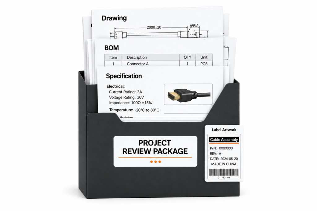
Send the strongest engineering evidence available: cable drawings, BOM, connector part numbers, pinout, reference samples, device-port photographs, test requirements, and acceptance criteria. Complete CAD files are helpful but are not always necessary for an initial review. When documentation is incomplete, clearly identify which requirements are confirmed and which still need engineering review before sampling or production.
Which Drawings and BOM Details Matter?
A useful cable drawing should make the assembly unambiguous. It can show both connectors, finished length, critical dimensions, cable construction references, pinout, connector exit direction, molding geometry, labels, and controlled tolerances. If the overmold must fit into a recessed port or restricted housing, the available clearance should also be shown because a connector that works electrically can still fail mechanically if the shell cannot enter the device.
The BOM adds information that may not be obvious from the drawing, including connector manufacturer and part number, wire specification, shielding material, jacket material, terminal, overmold material, heat-shrink parts, label, and packaging component. Drawing and BOM revisions should also match. A Rev. C drawing paired with a Rev. A BOM can quietly create a mixed specification even when both files look legitimate.
Can a Reference Sample Replace a Drawing?
A physical sample is extremely useful when replacing an old supplier or reconstructing a product whose original engineering records are incomplete, but it should not automatically be treated as a complete specification. A sample shows connector fit, approximate dimensions, flexibility, cable feel, molding appearance, and many visible construction details, yet it may not reveal the exact conductor specification, polymer grade, shielding coverage, tolerances, or hidden electrical acceptance criteria.
The most useful sample review defines which features must remain identical and which may change. For example, mating fit, pinout, finished length, and molded dimensions may be controlled while jacket color or packaging can be redesigned. When neither drawing nor BOM exists, Cablivo’s documented process allows an initial review using sample photographs, connector photographs, cable length, application information, and target quantity before determining what additional information is needed for sampling.
Which Functional and Reliability Tests Matter?
Testing becomes valuable when each test is connected to a real failure risk. Continuity testing can identify open circuits, shorts, and wiring errors. Data-transfer testing checks whether the cable performs the intended communication function in the agreed setup. Connector-fit verification catches mechanical mismatch, while visual inspection checks molded surfaces, print, dimensions, cable condition, and workmanship.
For cables that move repeatedly during use, swing or bending tests may be relevant. If the connector is frequently mated and unmated, insertion and withdrawal testing can provide useful durability information. Pull-force testing can be appropriate where termination or mechanical retention is critical. Cablivo’s documented USB cable testing scope can include charging-function testing, data-transfer testing, continuity, connector-fit checks, swing testing, connector-life testing, appearance inspection, logo-position checks, packaging inspection, and pre-shipment inspection according to project requirements.
What Compliance Evidence Is Actually Required?
Compliance requirements should be written as specific project deliverables rather than broad statements such as “all certificates required.” If the customer needs material declarations, component documents, customer-specific test reports, USB-related verification, or market-specific documentation, those items should be identified in the RFQ so the manufacturer can confirm what is available and what additional work may be needed.
This approach prevents a common mistake in custom cable sourcing: assuming that every cable with the same connector automatically carries the same certification status. Material, connector, finished cable, and end-product requirements may be different. Cablivo’s factual content boundaries follow the same principle and state that certification and testing requirements should be confirmed according to product type, target market, and project specifications rather than claimed universally.
| File or Test | What to Provide | What It Confirms | When It Matters Most | Acceptance Basis |
| Cable Drawing | Latest revision | Dimensions and construction | All custom assemblies | Approved drawing |
| BOM | Component list | Materials and part numbers | OEM/long-term supply | Approved BOM |
| Pinout | Wiring table | Electrical connection | Custom/legacy device | Approved schematic |
| Connector Drawing | Part/dimensions | Mechanical fit | Restricted port geometry | Mating check |
| Reference Sample | Approved physical cable | Fit and appearance | Supplier replacement | Golden sample |
| Continuity Test | Circuit definition | Open/short/wiring | Wiring-controlled projects | Pinout |
| Data Transfer Test | Device/test setup | Communication function | SuperSpeed applications | Agreed test method |
| Connector Fit | Mating device/fixture | Mechanical compatibility | Recessed ports | Approved fit |
| Swing Test | Cycle/load method | Flex durability | Frequently moved cable | Project standard |
| Connector Life | Cycle/force requirement | Mating durability | Frequent plug/unplug | Defined requirement |
| Pull Test | Force and fixture | Mechanical retention | Strain-sensitive assembly | Drawing/specification |
| Appearance Check | Limit sample | Mold/print/surface | Branded programs | Approved sample |
| Packaging Inspection | Artwork/pack spec | Shipment configuration | OEM/distribution | Approved packaging |
How Can You Avoid Quote Changes Later?
Quote changes are reduced by locking the quotation basis before production: connector models, cable construction, finished length, pinout, materials, tooling, tests, quantity, labels, and packaging. The goal is not to prevent legitimate engineering revisions. It is to make every revision visible so purchasing, engineering, sampling, and production are all working from the same controlled version rather than different assumptions.
Is Tooling Included in the Quote?
Tooling should be identified early because it may be separate from the recurring unit price. If the cable uses an existing molded connector design, existing tooling may be suitable. A unique shell, customer logo, custom strain relief, unusual cable exit, recessed-port geometry, grip feature, or protective shape may instead require a new mold or modification to an existing mold.
The quotation should distinguish recurring cable cost from one-time tooling or development charges when applicable. It should also state which design revision the tooling is based on. Changing molded geometry after machining begins is normally more disruptive than correcting the drawing during the engineering stage. Cablivo’s documented tooling equipment includes CNC, milling, grinding, and wire-cutting capability supporting mold development and adjustment for overmolded and custom molded cable structures.
How Should the Sample Be Approved?
A sample should be approved against a defined specification rather than because it simply “looks good.” Before the sample arrives, determine what needs to be checked: connector fit, pinout, finished length, cable OD, flexibility, molded dimensions, color, logo position, data function, power function, labeling, and relevant test results. Every controlled feature should have an approval basis that can be referred to later.
If engineering feedback changes the construction, the drawing or BOM should be revised instead of leaving the final requirement inside an email chain. Cablivo’s documented rules allow sample feedback and revision discussion while avoiding unrealistic claims that every first sample will be perfect or that unlimited revisions will always be free. The approved sample, drawing, BOM, and test scope can then become a much stronger production reference.
What Packaging and Labels Must Be Locked?
Packaging is often left until the cable itself has been approved, yet it can still change the final quotation. A bulk industrial project may require simple protective packing and carton identification, while an OEM or retail program may require individual bags, barcode labels, SKU information, inserts, printed boxes, master-carton markings, or customer-specific packing sequences.
Connector protection also deserves attention. If the connector shell, Micro-B plug, or molded surface can be damaged during transportation, protective caps, sleeves, partitions, trays, or another packing method may be required. Label information should be controlled in the same way as the cable specification because incorrect part numbers, barcodes, SKUs, or carton markings can create serious receiving problems even when the cable itself is correct. Cablivo’s fact base treats packaging and labeling as part of the complete project workflow.
How Can You Compare Quotations Fairly?
Send every shortlisted manufacturer the same drawing revision, BOM, quantity, test requirement, packaging specification, and application description. If Supplier A receives Rev. C while Supplier B receives Rev. A, their prices cannot be compared directly even if both quotation sheets show the same cable name. The same principle applies when one supplier includes custom molding, data testing, and individual packaging while another assumes a standard connector and loose bulk packing.
A useful comparison should therefore look beyond unit price and check the quotation basis. Confirm whether connector models, wire construction, shielding, jacket, molding, testing, tooling, and packaging are equivalent. A slightly higher quotation may represent a more complete scope, while a lower quotation may also be valid if the specification is truly equivalent. The important point is that differences should be visible rather than hidden inside assumptions.
| Quote-Control Item | Before Initial Quote | Before Sample | Before Mass Production | Main Risk if Missing |
| Application | Confirm | Confirm | Freeze | Wrong design priorities |
| Connector Models | Identify | Verify | Freeze | Mating failure |
| Length | Target | Confirm drawing | Freeze tolerance | Installation mismatch |
| Pinout | Draft | Verify | Freeze | Functional failure |
| AWG/Construction | Define or review | Verify sample | Freeze BOM | Electrical mismatch |
| Shielding | Define | Confirm structure | Freeze | Data-performance variation |
| Jacket | Select direction | Confirm sample | Freeze grade/spec | OD/feel variation |
| Overmold | Quote basis | Approve geometry | Freeze tooling revision | Tooling rework |
| Logo/Color | Define | Approve sample | Freeze reference | Cosmetic rejection |
| Data Test | Define | Validate | Freeze method | Undefined performance |
| Reliability Test | Identify | Validate method | Freeze criteria | Durability dispute |
| Quantity | Quote quantity | Update forecast | Confirm PO | Price/MOQ change |
| Packaging | Define level | Approve sample | Freeze specification | Cost/shipment mismatch |
| Label/Barcode | Identify | Review artwork | Freeze data | Receiving errors |
| Drawing Revision | Issue current file | Update changes | Freeze final | Multiple versions |
| BOM Revision | Preliminary | Update validation | Freeze final | Wrong components |
| Approved Sample | Not required | Create and review | Production reference | Sample-to-production mismatch |
Cablivo’s documented mass-production framework starts from approved samples, final drawings, final BOMs, material preparation, incoming inspection, cable cutting and stripping, soldering, connector assembly, overmolding, functional testing, appearance inspection, labeling, packaging, OQC, and shipment coordination. This sequence is important because the cable that was quoted, the cable that was sampled, and the cable that is manufactured should ultimately describe the same controlled product.

A useful USB-C to Micro-B 3.0 quotation does not require a perfect engineering package on the first day, but it does require enough information to separate confirmed requirements from assumptions. If your project already has a drawing, BOM, connector part numbers, pinout, cable construction, testing plan, and packaging specification, send those files together. If the design is still developing, begin with device information, connector photos, reference samples, required length, data and power requirements, application, and target quantity.
Cablivo supports custom cable projects through requirement review, connector and material confirmation, sample development, production preparation, testing, packaging, labeling, and shipment coordination. The company’s documented project process encourages customers to submit drawings, sample photographs, BOMs, connector models, cable length, AWG, quantity, application, packaging requirements, and test requirements before production decisions are finalized.
For a USB-C to Micro-B 3.0 cable project, a strong first RFQ can include the following items:
- Cable drawing or reference sample
- USB-C connector information
- SuperSpeed Micro-B connector information
- Mating-device or port photographs
- Required finished cable length
- AWG or electrical requirements
- Required data-transfer function
- Required power function
- Approved pinout
- Shielding structure
- Jacket material and cable OD
- Overmold and strain-relief requirements
- Logo and color requirements
- Functional and reliability tests
- Sample quantity
- Initial production quantity
- Packaging and labeling requirements
- Target market or project-specific documentation requirements
The objective is not to create the longest RFQ possible. It is to make the first quotation technically meaningful, commercially comparable, and useful enough to carry the project into sample validation without repeatedly reopening basic specifications. When those inputs are clear, the conversation with a cable manufacturer becomes much more productive and the path from quotation to sample, production, testing, packaging, and delivery becomes easier to control.



