 Skip to content


An RF coaxial cable assembly can look deceptively simple on a purchasing list: one connector at each end, a cable length and an order quantity. In practice, that short description may leave out most of the information that determines whether two manufacturers are actually quoting the same product. Connectors that look almost identical can have different genders, mounting styles, orientations or electrical versions. Coaxial cables with similar outside diameters can behave very differently at the required operating frequency. Even a seemingly straightforward finished length can be interpreted differently when the measurement reference points are not defined.
To quote an RF coaxial cable assembly accurately, a manufacturer normally needs the connector specification at both ends, coaxial cable type, finished length and tolerance, operating frequency, impedance and any applicable RF performance limits, routing and environmental conditions, test requirements, order quantity, and supporting files such as drawings, BOMs, component datasheets or approved samples. Labeling, packaging and documentation requirements should also be identified before the quotation is finalized.
The practical goal is not to create unnecessary paperwork. It is to make sure engineering, procurement and manufacturing teams are talking about exactly the same cable. Consider a request that simply reads, “SMA to SMA, 500 mm, 1,000 pcs.” Three factories might return three prices quickly, but one may select a different cable construction, another may assume a different connector orientation, and a third may include only continuity checks while your project later expects RF performance testing. The numbers may look comparable even though the products are not.
What RF Cable Specifications Are Needed for a Quote?
An accurate RF cable quotation begins with four fundamentals: the exact connectors at both ends, the coaxial cable specification, finished length and tolerance, and the required operating frequency. Together, these details establish the physical and electrical baseline of the assembly. If any one of them is unclear, a manufacturer may need to make assumptions that can change component sourcing, manufacturing method, test scope, cost and final application suitability.
Which Connectors Are Required at Each End?
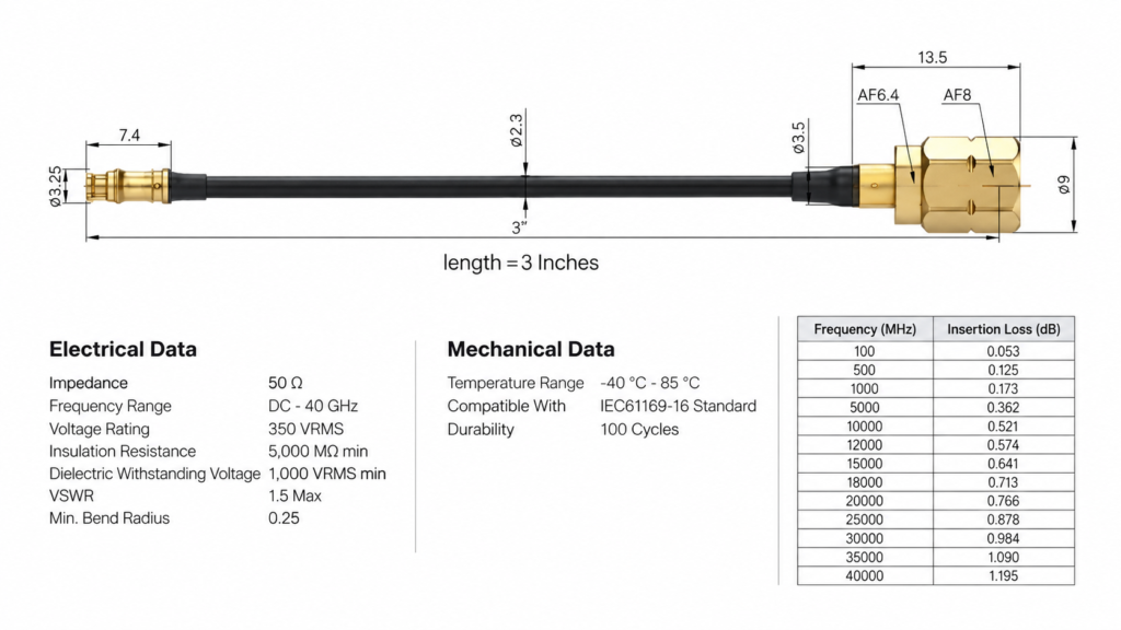
A connector family name is rarely a complete specification. Writing “SMA to SMA” or “BNC to SMA” may identify the general interface, but the RFQ still needs to distinguish End A from End B and, where relevant, state plug or jack, straight or right-angle orientation, bulkhead or free-hanging construction, mounting style and the exact manufacturer part number. Connector orientation also affects how the cable leaves the device, how much installation clearance is available and whether unwanted mechanical stress is placed on the termination.
Connector accuracy is particularly important when visually similar RF interfaces exist in several versions. RF/coaxial projects may involve SMA, SMB, BNC, TNC, N-Type, MCX, MMCX, FAKRA, U.FL, IPEX or project-specific RF connectors, but the exact model, impedance, frequency suitability and mating requirements still need to come from the project specification rather than appearance alone. Cablivo’s documented RF/coaxial project scope specifically treats connector confirmation as a required engineering step instead of something that should be guessed from photographs.
When a manufacturer part number is unavailable, provide more than one photograph. A front view, side view and close-up of the mating interface can help, while an equipment-side connector drawing or dimensioned sample is even more useful. For miniature RF connectors, small dimensional differences may matter. The purpose of these references is not to force a final identification from an image but to identify what still needs to be confirmed before sampling or production.
What Coaxial Cable Type Is Required?
If a coaxial cable has already been approved during product development, the cleanest RFQ identifies the exact cable manufacturer and part number. That removes ambiguity around conductor construction, dielectric, shielding, jacket, outside diameter, flexibility and published RF characteristics. If substitutions are allowed, that rule should also be written clearly so the supplier knows whether an alternative cable can be proposed for engineering approval or whether the specified component must be used without substitution.
When the exact cable has not yet been frozen, the RFQ should describe the real application rather than asking for a generic “good RF cable.” Useful inputs include operating frequency, required impedance, routing space, target outside diameter, flexibility, shielding expectations, mechanical environment and any insertion-loss or other RF target already established by system engineering. A thin cable may be convenient in a compact enclosure, while another construction may be considered when lower transmission loss, mechanical robustness or a different installation requirement has higher priority.
Shielding is also part of the cable decision. Depending on the cable construction, RF and signal-sensitive products may use braided shielding, foil-related shielding or combined structures. Cablivo’s verified manufacturing system includes high-speed braiding and foil-wrapping processes that support shielding structures for RF/coaxial, communication and other signal-sensitive cable projects. These capabilities support structure customization, but the final shielding design still needs to be selected according to the customer’s application and technical specification.
What Cable Length and Tolerance Are Required?
Finished length should be treated as a controlled engineering dimension rather than a single number copied into a purchase request. A specification such as “500 mm” can still produce disagreement if it does not state where measurement begins and ends. Depending on the assembly, the controlling dimension may be overall tip-to-tip length, distance between connector reference planes, cable jacket length between connector bodies or another dimension explicitly identified on the drawing.
Tolerance should reflect what the installation actually needs. An unnecessarily tight tolerance can increase cutting, assembly and inspection effort without delivering useful value when the cable has generous routing space. An overly loose tolerance can create the opposite problem inside compact equipment, where excess cable may interfere with nearby components or the shortest acceptable cable may no longer reach the mating port. The tolerance therefore needs to come from mechanical fit and system requirements rather than a generic habit.
For projects with several lengths, each finished length should be treated as a separate SKU or clearly separated quotation line. A request for 300 mm, 500 mm and 1,000 mm versions is much easier to price and control when each version has its own quantity and drawing reference. Connector orientation should be reviewed at the same time, because a right-angle interface can substantially change the usable routing path even when the nominal cable length remains unchanged.
What Frequency Range Must the Assembly Support?
The RFQ should define the frequency the complete assembly actually needs to support rather than assuming that a connector family name automatically determines performance. An RF cable assembly is a transmission path made from the cable, connector interfaces and terminations. The behavior of the complete assembly therefore depends on how those elements work together, not simply on whether one component is marketed for high-frequency applications.
If the equipment operates across a frequency band, provide the full operating range. If one band or specific test condition is particularly important to system performance, identify it. When one cable assembly is intended for several equipment variants, the highest frequency that genuinely needs to be supported can help prevent an under-specified cable from being quoted for the higher-frequency version. At the same time, there is little benefit in specifying extreme frequency performance that the real product will never use.
Cablivo’s RF/coaxial content boundaries require application frequency, impedance and signal-testing requirements to be confirmed according to customer technical specifications. Unsupported fixed frequency, insertion-loss or impedance performance data should not be presented as universal capabilities. That same discipline is useful when preparing an RFQ: unknown performance requirements should stay visible as open engineering items instead of being silently filled in by the supplier.
| Specification Item | Useful RFQ Detail | Project Decision | Risk if Missing |
| Connector A | Family, gender, orientation, mounting, P/N | Exact component or approved equivalent | Wrong mating interface |
| Connector B | Family, gender, orientation, mounting, P/N | Exact component or approved equivalent | Installation failure |
| Coaxial cable | Approved P/N or defined requirements | Fixed cable or engineering alternative | Different RF performance |
| Impedance | System-required value | Match equipment and RF path | Electrical mismatch |
| Finished length | Controlled reference points | Separate by SKU | Poor equipment fit |
| Length tolerance | Drawing requirement | Tight only where necessary | Cost increase or poor fit |
| Frequency | Actual operating range | Based on system requirement | Under-specified RF path |
| Shielding | Required cable construction | Based on interference and application | Signal-stability risk |
Which RF Performance Requirements Must Be Defined?
RF performance requirements should be stated whenever they affect product acceptance. At minimum, confirm operating frequency and required impedance. Performance-sensitive projects may additionally control insertion loss, return loss or VSWR, PIM, phase behavior or other RF parameters. The RFQ should also explain how those requirements are verified, whether testing is performed on every assembly or by sampling, and whether recorded measurement data or reports are required.

What Impedance Must the Assembly Match?
Characteristic impedance should be explicitly identified in a controlled RF specification. Many RF communication, antenna and test systems commonly use 50-ohm transmission paths, while 75-ohm systems are widely encountered in applications such as video, broadcast and certain distribution systems. These are common industry values, but neither should be assumed for a specific project simply because a connector looks familiar.
The safest source for the required impedance is the mating equipment specification, RF module datasheet, antenna documentation, existing approved cable drawing or another controlled engineering document. Connector, cable and mating equipment then need to be reviewed as one transmission system. If the RFQ already specifies impedance in the drawing, repeating it in the quotation summary can provide another useful checkpoint for purchasing and engineering teams.
This also matters when comparing supplier prices. A mechanically similar cable built around an incorrect impedance is not an equivalent alternative. If impedance is still unknown during early product development, the project can begin with a preliminary review, but the item should remain open until the mating system is confirmed rather than allowing the manufacturer to choose a value without technical justification.
Which Loss and Matching Limits Apply?
Insertion loss, return loss and VSWR describe different aspects of RF transmission quality, but the correct acceptance values depend on the actual application. Insertion loss indicates how much signal is lost through the assembly, while return loss and VSWR are commonly used to evaluate impedance matching and reflected energy. A short internal RF connection may have very different acceptance needs from an antenna feeder, test lead or another performance-sensitive transmission path.
The RFQ should therefore avoid broad requirements such as “best RF performance” or “low loss” when the engineering team already has measurable acceptance criteria. If insertion loss is controlled, state the maximum permitted value and the frequency or frequency range to which it applies. If return loss or VSWR is controlled, identify its required limit and measurement band. When those limits are not yet established, leave them as engineering decisions that need to be resolved before the production specification is frozen.
Over-specification can be just as unhelpful as under-specification. Extremely tight performance limits may narrow cable and connector options or require additional testing even when the system does not need that level of control. A useful RFQ aims for the performance the equipment actually requires rather than automatically asking for the most demanding available specification.
Is Low PIM or Phase Performance Required?
Low-PIM, phase-matched and phase-stable cable assemblies belong to more specialized RF applications and should be requested only when the system genuinely needs them. Passive intermodulation can be important in RF systems where unwanted nonlinear products must be kept within a defined limit. Phase matching may be necessary when several parallel RF paths must maintain a controlled relationship, while phase stability can matter in certain test, measurement or signal-processing environments.
These requirements can influence connector selection, cable construction, material control, handling, manufacturing process and test scope. A simple note saying “low PIM” or “phase stable” does not provide enough information to quote the work accurately. The technical specification should define the relevant acceptance limit, test frequency, test condition and other system requirements. For matched assemblies, it should also identify how many cables belong in one set and how matching is evaluated.
If the application does not require these controls, adding them can increase component and testing costs without improving the real product. Accurate RFQ preparation therefore means identifying which performance attributes matter to the application and deliberately leaving unnecessary ones out.
Which RF Tests or Reports Are Required?
Testing belongs in the RFQ because every requested inspection or measurement adds a defined task to manufacturing and quality control. A project may require connector-fit verification, dimensional checks, cable-length checks, visual inspection and electrical continuity-related verification. Other RF applications may require project-defined measurements such as insertion loss, return loss, VSWR or additional RF characteristics using appropriate test equipment and acceptance criteria.
Cablivo’s verified RF/coaxial quality directions include connector-fit checks, continuity testing, LCR-related evaluation, appearance inspection, cable-length inspection, label inspection and packaging inspection. The company’s documented content boundaries do not support claiming universal fixed values for frequency, insertion loss or impedance performance; such requirements need to be confirmed from the actual customer specification.
An RFQ should also define the amount of testing expected. If the project requires 100% testing, say so. If sampling is acceptable, identify the inspection plan where one has already been established. If raw measurement values, test reports or lot-level records are required, include those deliverables before the price is finalized. Testing added after quotation can change labor, equipment time, data handling and delivery planning.
| Performance Item | Information to Define | Typical Relevance | Possible Quote Impact |
| Impedance | System-required value | Controlled RF paths | Cable and connector selection |
| Operating frequency | Full operating/test range | All RF applications | RF suitability and test scope |
| Insertion loss | Maximum limit when controlled | Longer or sensitive signal paths | Cable selection and measurement |
| Return loss | Minimum requirement when controlled | Matching-sensitive systems | Termination and RF testing |
| VSWR | Maximum requirement when used | Antenna and communication systems | Test equipment and inspection |
| PIM | Limit and defined test condition | PIM-sensitive applications | Specialized process and testing |
| Phase matching | Tolerance and reference condition | Multi-channel RF systems | Sorting and matched-set control |
| Test records | Pass/fail, report or raw data | Document-controlled projects | Inspection and documentation cost |
What Mechanical and Environmental Details Matter?
Mechanical and environmental information explains how the RF coaxial cable will actually live inside the final product. Routing space, bend conditions, movement, connector orientation, mounting style, temperature, humidity, vibration and other exposure can affect cable and connector selection. A cable can meet an electrical requirement on a test bench yet still be unsuitable if it cannot fit the equipment, withstand the expected movement or survive the real operating environment.
How Will the Cable Be Routed?
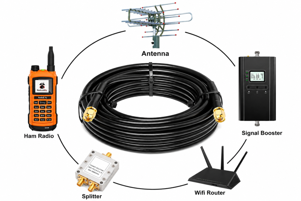
Routing information is often missing from an RFQ because it appears to be purely mechanical, but installation geometry can influence cable diameter, flexibility, connector orientation and even the realistic choice of RF construction. A cable installed between two boards inside compact equipment may have only a small amount of clearance behind the connector. A thicker cable may offer attractive electrical characteristics but be too stiff to make the required turn without stressing the mating port.
A routing sketch does not need to be complicated. A marked equipment photograph, simplified CAD screenshot or drawing showing the two connector positions, first cable bend and nearby walls can reveal constraints that a standalone cable drawing cannot. This becomes particularly useful when the assembly uses right-angle connectors or when the cable must pass through a narrow opening before reaching the next module.
Installation frequency also matters. A cable fitted once and left untouched has a different mechanical duty from a cable that needs to be disconnected during maintenance. Providing that context allows engineering teams to judge the assembly as part of the equipment rather than as an isolated length of coaxial cable sitting on a workbench.
What Bend or Flexibility Requirements Apply?
“Flexible coaxial cable” is not a complete mechanical requirement because flexibility depends on how the cable will actually be used. A cable that is bent once during installation is different from one that is repositioned periodically during equipment service, and both are different from a cable subjected to repeated movement during normal operation. The RFQ should describe which condition applies rather than relying only on a general adjective.
Minimum bend radius should normally be checked against the selected cable specification, but the customer can provide the tightest routing path the cable must follow. Particular attention should be paid to the area immediately behind the connector. Even when a cable body can accept a given bend, forcing that bend directly at the termination may create concentrated mechanical stress.
Flexibility also involves trade-offs. Cable diameter, shielding construction, jacket, mechanical durability and RF loss can all influence the decision. A highly flexible cable may be valuable in moving equipment but unnecessary for a fixed internal connection. Cablivo’s RF/coaxial project scope recognizes bending requirement as a normal customization input, allowing the cable construction to be reviewed against the installation rather than selected from appearance alone.
Are Connector Orientation and Mounting Important?
Connector orientation can determine whether an otherwise correct assembly physically fits the equipment. A straight connector creates one cable exit path, while a right-angle connector changes the direction immediately after the interface. When two right-angle connectors are used on the same cable, their rotational relationship may also need to be controlled so both ends line up with the intended mounting positions.
For panel-mounted or bulkhead connectors, the RFQ should provide relevant panel information when it affects installation. Panel thickness, mounting hardware and required connector projection can all matter. Nuts, washers, protective caps and similar accessories should also be included when they are part of the supplied assembly rather than treated as assumptions after the purchase order is placed.
The simplest way to avoid orientation errors is to show the complete cable in a dimensioned drawing with clear reference views. If clocking matters, define it relative to a recognizable datum. Mechanical configuration should be frozen before production because changing orientation after sample approval can require a connector change, termination change or other manufacturing adjustment rather than a minor documentation update.
What Environment Will the Assembly Operate In?
Environmental requirements should describe real exposure instead of combining every possible extreme condition into a single specification. Depending on the application, useful inputs may include operating and storage temperature, humidity, moisture, vibration, abrasion, UV exposure, chemical exposure, salt-related conditions or repeated movement. An RF cable inside climate-controlled test equipment does not have the same risk profile as a cable routed through industrial machinery or installed in an outdoor communication system.
These conditions can influence jacket material, connector materials, plating, mechanical protection and testing requirements. A project exposed to corrosive environments may need a different connector-material review from an indoor assembly. A cable operating through wide temperature and humidity changes may need additional material and reliability evaluation. The correct response is application-specific rather than automatically describing every RF cable as suitable for harsh environments.
Cablivo’s documented broader test resources include environmental reliability, connector-life, tensile and corrosion-related test capabilities for applicable cable projects, but test conditions and pass/fail criteria must still be defined according to the relevant project specification. Certification, environmental rating and performance claims should not be generalized across products without actual supporting requirements and evidence.
| Application Condition | Information to Provide | Engineering Concern | Possible Effect |
| Tight internal routing | Available space and routing path | Stiffness and connector loading | Cable size and connector orientation |
| Fixed installation | Final cable path | Mechanical fit | Length and bend radius |
| Repeated movement | Motion pattern and duty | Fatigue at cable and termination | Cable construction |
| Panel mounting | Panel geometry and hardware | Mechanical fit | Connector style and accessories |
| Outdoor use | Moisture, temperature, UV exposure | Material durability | Jacket and connector selection |
| Industrial equipment | Vibration, abrasion, oil or chemicals | Long-term reliability | Protection and materials |
| High humidity | Operating/storage conditions | Corrosion and material behavior | Connector and jacket review |
| Sensitive shipping | Connector and cable protection | Transit damage | Packaging structure |
What Files and Order Details Should You Send?
A strong RFQ combines technical documentation with commercial information. Send the latest drawing, BOM, connector and cable datasheets, sample information or clear product photographs available to you, then add quantity by SKU, labeling, packaging and documentation requirements. These references reduce assumptions during sourcing and costing and help engineering, procurement, quality and production teams work from the same project revision.

Do You Have a Drawing, BOM, or Approved Sample?
A controlled drawing is usually the clearest starting point for an RF coaxial cable quotation because it can combine connector callouts, cable type, finished length, tolerance, orientation, label requirements and special notes in one document. A BOM adds component-level information and may identify connector manufacturer part numbers, coaxial cable part numbers, protective caps, heat-shrink components, labels and packaging materials already approved by the engineering team.
An approved physical sample can also be valuable when historical documentation is incomplete, but appearance alone cannot reveal every specification. Frequency range, characteristic impedance, internal cable construction and acceptance tests may not be identifiable from the finished product. The sample therefore works best as one reference within a broader specification package rather than automatically replacing a drawing or BOM.
When complete drawings are not available, customers can still start with overall sample photographs, close-up connector photographs, cable length, application details and target quantity. Cablivo’s documented project process uses this information for preliminary review so missing specifications can be identified before sampling rather than allowing them to become hidden assumptions inside the quote.
Which Part Numbers or Datasheets Are Available?
Exact component part numbers are especially useful in RF assemblies because similar-looking connectors and cables can have substantially different technical characteristics. When the existing product has already been qualified using a defined connector or cable manufacturer, include those references directly in the RFQ. This gives the supplier a clear purchasing target and reduces the risk of selecting an apparently compatible but technically different component.
If alternatives are acceptable, define the approval rule instead of leaving substitution completely open. For example, a project may allow an equivalent component only after the manufacturer provides the relevant datasheet and engineering reviews the interface, dimensions and required electrical characteristics. That is very different from allowing any visually similar connector to be used without review.
When the original part number is unknown, equipment model information, mating connector drawings, connector dimensions, high-resolution photographs and cable markings can help identify the next engineering step. For BOM-based projects, Cablivo’s documented review process can cover connector models, cable specifications, materials, labels, packaging components and possible sourcing risks before quotation or sampling.
What Quantities Are Needed?
Quantity affects sourcing, process planning, test workload, packaging and commercial terms, so it should be provided by actual configuration rather than only as one total project number. A program containing several cable lengths, connector combinations or labels may be one purchase order commercially but represents several distinct manufacturing configurations. Each SKU therefore needs its own quantity if the quotation is expected to be accurate.
It is also useful to distinguish prototype demand, first production quantity and expected repeat demand where those numbers are genuinely available. Prototype quantity helps define evaluation needs, while production volume affects material sourcing and manufacturing planning. Long-term estimates can help a manufacturer understand potential supply-continuity requirements, but they should be labeled as estimates rather than guaranteed orders when the project has not yet reached that stage.
For many Cablivo custom cable projects, the documented MOQ starts from 500 pieces, while the final MOQ depends on connector type, cable structure, material, overmolding or tooling requirements, packaging plan and order quantity. The exact commercial condition for an RF assembly therefore needs to be confirmed after the product structure and supply requirements are understood.
Are Labeling and Packaging Requirements Defined?
Packaging is not merely a cosmetic decision for RF coaxial cable assemblies. Small RF connectors may be vulnerable to impact, contamination, crushing or poor handling, while the cable itself may be damaged if it is forced into an inappropriate coil or compressed during transportation. Multi-SKU projects create another practical risk because several cables can look almost identical even though their connectors, lengths or test requirements differ.
Customer part numbers, barcode files, label text and any traceability information should therefore be provided early enough to become part of the controlled order information. If individual bags, connector caps, protective trays, length labels or special separation after testing are required, include those details in the RFQ instead of introducing them only after manufacturing begins.
Cablivo’s RF/coaxial packaging guidance specifically identifies connector protection, cable-length identification, bend protection, crush protection, individual packaging, labels, separation after testing and overall transportation protection as relevant considerations. These details become particularly valuable for equipment manufacturers, system integrators and distributors receiving several similar RF cable configurations in one shipment.
| RFQ File or Detail | Preferred Information | Most Useful When | Main Risk Reduced |
| Drawing | Latest controlled revision | New and repeat production | Dimensional misunderstanding |
| BOM | Cable, connectors and accessories | Qualified or transferred projects | Component errors |
| Datasheets | Approved component information | Alternative sourcing | Incorrect substitutions |
| Physical sample | Approved reference | Legacy designs | Construction mismatch |
| Product photos | Complete cable and connector close-ups | No formal drawing available | Initial identification errors |
| Quantity | Quantity by configuration | Every quotation | Incorrect price comparison |
| Label file | P/N, barcode, SKU or revision | Multi-SKU programs | Product mix-ups |
| Packaging specification | Coil, bag, protection and carton rules | Export shipment | Transit damage |
| Test specification | Test item, limit and report need | Performance-controlled RF projects | Unquoted inspection scope |
| Revision status | Drawing/BOM revision | Repeat orders | Obsolete specification used |
How Do You Prepare a Complete RF Coaxial Cable RFQ?
A complete RF coaxial cable RFQ should function as a compact technical package. It identifies the connectors, cable, finished length, impedance, frequency, RF performance requirements, mechanical conditions, test scope, quantity, supporting documents, labeling and packaging. Different configurations are separated by SKU, while unresolved parameters remain clearly marked for engineering review instead of being guessed. Before volume production, the agreed specification and approved sample should become controlled references.

What Should an RFQ Checklist Include?
The best RFQ checklist is not necessarily the longest one. It is the checklist that captures every decision likely to change product construction, component cost, manufacturing method, inspection scope or application fit. Begin with Connector A, Connector B, cable type and finished length because these define the basic assembly. Add characteristic impedance and operating frequency because they establish the essential RF context for cable and connector selection.
Next, include performance requirements that genuinely control acceptance. Insertion loss, return loss, VSWR, PIM or phase requirements should be added only when the system needs them, but they need to be specific when included. Mechanical routing, connector orientation and environmental conditions follow because they can change the practical suitability of the selected cable construction.
Testing, documentation, quantity, labeling and packaging complete the RFQ package. Cablivo’s documented project-information framework similarly encourages customers to provide drawings, sample photos, BOMs, connector models, cable length, application details, target quantities, testing requirements and packaging information before quotation. Clear inputs make engineering review faster and reduce the risk that commercial prices are built around different technical assumptions.
How Should Multiple Lengths or SKUs Be Listed?
Every technically different RF cable configuration should have its own identifiable quotation line. If three assemblies use the same connectors but different lengths, they are three configurations. If two cables share the same length but use different coaxial cable part numbers, connector orientations, labels or RF performance requirements, they should also be separated where those differences affect manufacturing or inspection.
A clear SKU structure makes supplier quotations easier to compare because each price corresponds to one defined configuration. It also becomes valuable later when the project enters repeat production. A product family can easily grow from a few cable versions into many similar assemblies, and without disciplined identification the relationship between drawings, samples, labels and purchase orders can become difficult to control.
Revision management is equally important. If a connector changes after sample evaluation, the drawing revision and affected SKU information should be updated rather than leaving the change buried in an email thread. For long-term supply projects, configuration control reduces the chance that an obsolete drawing or historical sample is accidentally used for a repeat order.
| SKU | Cable | Connector A | Connector B | Length | RF Requirement | Quantity |
| RF-001 | Approved P/N | Drawing-defined | Drawing-defined | 300 mm | Per approved specification | Project quantity |
| RF-002 | Approved P/N | Drawing-defined | Drawing-defined | 500 mm | Per approved specification | Project quantity |
| RF-003 | Approved P/N | Drawing-defined | Drawing-defined | 1,000 mm | Per approved specification | Project quantity |
What If Some Specifications Are Still Unknown?
Incomplete specifications are common during product development and do not prevent a project from starting. They simply mean that the first step is an engineering review rather than a final production quotation. A team may already know the mating connector, equipment layout, approximate cable length and operating frequency while the final cable part number is still under evaluation. That information is still useful because it defines the questions that need to be resolved next.
Photographs, old samples, equipment connector drawings and application descriptions can all help fill early gaps. If a physical sample is available but no drawing exists, the sample can provide structure and dimensional clues while engineering information confirms parameters that cannot be identified from appearance. Open items should be listed explicitly so everyone knows which parts of the quotation are preliminary.
Cablivo’s documented engineering scope includes requirement review, drawing review, sample review, BOM review, connector confirmation, material selection, DFM feedback, prototype development, sample revision and production preparation. The company’s fact library also specifically avoids claiming that any cable can be designed or manufactured correctly without sufficient project information. This approach turns missing information into visible engineering tasks instead of invisible assumptions.
Which Details Should Be Frozen Before Production?
Before an RF cable project moves from sample validation into volume production, quotation inputs need to become a controlled manufacturing specification. The final drawing or equivalent document should confirm connector part numbers, coaxial cable, finished length and tolerance, connector orientation, impedance, operating frequency, applicable RF performance limits, inspection plan, labeling and packaging. Approved substitutions should also be recorded rather than existing only in informal correspondence.
The approved sample needs to correspond to the correct drawing revision. Sample approval is useful because it confirms real connector fit, routing, handling and appearance, but the sample alone is not sufficient for long-term configuration control. The drawing or BOM remains important when materials need to be purchased again months later or when another production lot is prepared.
Cablivo’s documented production scope links approved samples and final drawings/BOMs with material preparation, production processing, functional checks, appearance inspection, labeling, packaging, OQC and shipment coordination. Production schedules and lead times depend on product structure, material availability, connector sourcing, order quantity, testing requirements and packaging rather than one universal fixed promise.
| Final RFQ Check | Clear Before Final Quote | Frozen Before Production | Action if Still Open |
| Connector A and B | Yes | Yes | Engineering confirmation |
| Coaxial cable | Preferably | Yes | Evaluate cable options |
| Length and tolerance | Yes | Yes | Confirm installation geometry |
| Impedance | Yes | Yes | Check mating system |
| Frequency | Yes | Yes | Confirm equipment requirement |
| RF performance limits | If applicable | Yes when controlled | Define acceptance criteria |
| Mechanical routing | If restrictive | Yes | Supply drawing or photo |
| Environment | If relevant | Yes | Confirm real conditions |
| Test scope | Yes | Yes | Quote testing separately if unresolved |
| Quantity by SKU | Yes | Purchase-order controlled | Separate configurations |
| Label artwork | If required | Yes | Submit approved file |
| Packaging | Quote-level requirement | Yes | Approve before production |
| Drawing/BOM revision | Current version | Frozen version | Update document control |
| Approved sample | Not always available at RFQ | Recommended before volume production | Complete validation |
Send Your RF Coaxial Cable Project for Review
A useful RF coaxial cable quotation is more than a price attached to a connector name and cable length. It is the result of translating the equipment requirement into a controlled assembly specification that engineering, purchasing, production and quality teams can all understand. The correct connectors, cable construction, dimensions, RF expectations, routing conditions, test scope, labeling and packaging need to point to the same final product before commercial comparisons become meaningful.
If your project already has a drawing, BOM or approved specification, those files provide the strongest starting point. When documentation is incomplete, clear sample photographs, close-up connector photographs, cable length, application information, frequency requirements where known, target quantity and required tests can still support an initial review. Cablivo’s documented inquiry process allows available project information to be reviewed first so the missing details can be identified before sampling or production planning.
Cablivo is the overseas-facing brand of Shenzhen Tianxiaowei Electronics Co., Ltd. Its documented manufacturing base includes 18 years of industry experience, more than 20,000 square meters of factory space, a team of more than 1,500 people and three manufacturing bases. RF/coaxial cable manufacturing is included within its broader custom cable, wire harness and cable assembly business, together with drawing review, connector confirmation, material selection, sample development, production, quality inspection, packaging, labeling and shipment coordination.
For RF and other signal-sensitive cable projects, the company’s documented manufacturing capabilities include shielding-related braiding and foil-wrapping processes. Exact operating frequency, impedance, insertion-loss targets and other RF performance requirements remain dependent on the customer’s technical specification rather than being treated as generic promises. This distinction helps keep quotations tied to the real application and gives both engineering and procurement teams a clearer basis for evaluating the proposed assembly.
Send your drawing, BOM, connector model, coaxial cable specification, finished length, target quantity, application details, testing requirements and packaging plan to begin an RF coaxial cable assembly review. A well-prepared RFQ gives the manufacturer a better chance to quote the correct construction from the beginning, reduces unnecessary clarification cycles and creates a more reliable path from sample approval to repeatable production.



