 Skip to content


An unshielded multi-conductor cable assembly can look straightforward on a drawing: one outer jacket, several insulated conductors, and connectors or terminations at one or both ends. In practice, that simple appearance can hide many decisions that affect materials, processing, testing, production planning, and final cost. Two requests described as “six-core unshielded cable, one meter long” can become completely different assemblies once conductor gauge, connector part numbers, pinout, insulation, jacket, length tolerance, labels, operating environment, testing requirements, and production quantity are confirmed.
An accurate quotation normally requires conductor count and AWG, conductor and insulation materials, jacket specification, finished cable length and tolerances, connector or terminal details, pinout and wire sequence, voltage and current requirements, signal function, application environment, drawings or BOM, target quantity, required tests, packaging instructions, target market, expected timeline, and shipping destination. Complete information reduces hidden assumptions and makes quotations easier to compare.
That distinction matters because a low-looking unit price is not useful when it is based on the wrong connector, a different conductor size, a cheaper jacket material, or a simplified inspection plan. A project can appear competitive during the first RFQ and then change substantially after engineering review because several undefined items were interpreted differently. The better approach is to treat the RFQ as the first controlled definition of the cable rather than a request for a number. Once the same technical definition is shared by engineering, procurement, quality, and the manufacturer, both quotation and sample development become much more predictable.
What Cable Specifications Are Needed for the Quote?
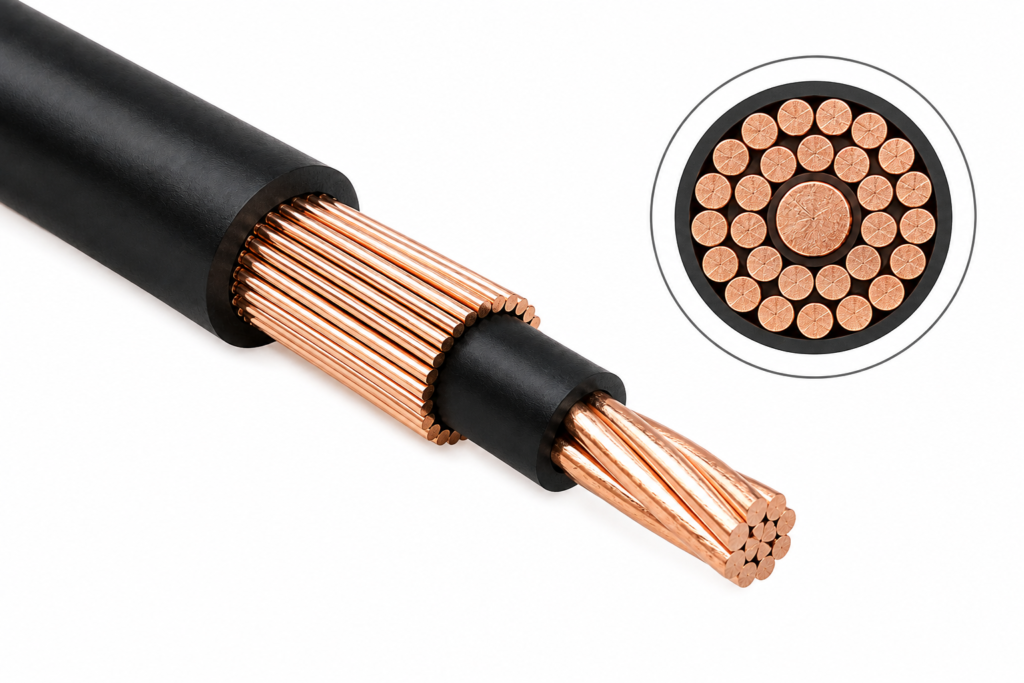
An accurate quote starts with a cable construction that is defined clearly enough for different manufacturers to price essentially the same product. The most important inputs are conductor count, AWG or conductor cross-section, conductor construction, insulation, jacket material, finished length, tolerances, conductor identification, cable diameter when controlled, and confirmation that the assembly is intentionally unshielded.
| Cable Specification | Information to Provide | Why It Affects the Quote |
| Conductor count | 2-core, 4-core, 6-core, 12-core, etc. | Changes material, OD and processing |
| Wire gauge | AWG or mm² | Affects copper usage, terminals and cable size |
| Conductor construction | Stranded or specified construction | Influences flexibility and processing |
| Insulation | Material, color, controlled thickness | Affects electrical and environmental use |
| Jacket | Material, color, OD or specification | Affects protection, flexibility and cost |
| Cable length | Overall length and tolerance | Controls material consumption and cutting |
| Shielding | Confirm unshielded | Prevents different structural assumptions |
| Identification | Core colors or wire numbers | Supports assembly and inspection |
Conductor Count and AWG
The conductor count should represent the real circuit rather than simply repeat a catalog description such as “multi-core cable.” A six-conductor assembly may use six identical wires, but another six-conductor design could use four signal conductors and two larger power conductors. The processing route, terminal selection, finished diameter, stripping operations, and raw-material consumption can therefore change even when both products are casually described as six-core cables.
Wire gauge deserves the same attention. AWG influences copper content, conductor resistance, cable diameter, flexibility, terminal compatibility, stripping settings, connector cavity limitations, and available routing space. As a size reference, AWG 24 is about 0.205 mm², AWG 22 about 0.326 mm², AWG 20 about 0.518 mm², AWG 18 about 0.823 mm², and AWG 16 about 1.31 mm² in nominal conductor cross-sectional area. These figures help compare conductor sizes, but actual selection should still consider current, voltage, cable length, temperature, connector limits, installation method, and acceptable voltage drop.
| AWG | Approx. Cross-Section | Relative Size | Typical Quotation Effect |
| 24 AWG | 0.205 mm² | Small | Lower copper usage and smaller terminals |
| 22 AWG | 0.326 mm² | Small–medium | Moderate cable size and material usage |
| 20 AWG | 0.518 mm² | Medium | More copper and larger termination requirements |
| 18 AWG | 0.823 mm² | Medium–large | Increased OD and material use |
| 16 AWG | 1.31 mm² | Large | Greater routing and connector-fit considerations |
A common sourcing problem occurs when an AWG value is copied from an older product without checking whether the new design carries the same load or follows the same routing conditions. If the gauge has already been validated, place it clearly in the drawing or BOM. If it is still open, provide voltage, current, cable length, application conditions, and connector information so the point can be reviewed rather than hidden inside the quotation.
Insulation and Jacket
The insulation around each conductor and the outer jacket around the complete cable influence much more than appearance. Insulation contributes to conductor separation, electrical protection, dimensional control, temperature behavior, and the internal structure of the cable. The jacket affects flexibility, abrasion resistance, handling, environmental exposure, finished diameter, color, and how the cable behaves during installation and long-term use.
When the project already specifies PVC, TPE, TPU, PUR, PE, or another material, include that requirement in the RFQ rather than allowing the material to be chosen silently. If the exact material remains open, explain the operating conditions instead. “Stationary indoor cable inside an equipment cabinet” provides useful context, while “cable repeatedly handled during maintenance with possible oil exposure” points toward a different set of priorities. Cablivo’s factual manufacturing base includes conductor preparation, insulation extrusion, outer-jacket extrusion, cutting, stripping, assembly, and related cable-manufacturing processes, allowing material and structural requirements to be reviewed as part of a complete cable project rather than only at final assembly.
Length and Tolerance
Overall cable length should be defined from a clear measurement reference. Depending on the assembly, the controlled dimension may run from connector face to connector face, strain-relief exit to strain-relief exit, housing edge to cut end, or between another pair of defined points. Simply writing “1 meter” can create disagreement when engineering, production, and incoming inspection measure the product from different physical locations.
Tolerance also changes how the cable is manufactured and inspected. An assembly routed loosely inside a large enclosure may allow more variation than one installed between two fixed interfaces inside compact equipment. If strip lengths, exposed conductors, branch points, heat-shrink positions, sleeve locations, or label positions are important, those dimensions should be shown as well. Cablivo’s documented production system includes automatic cable cutting and 86 multi-core high-speed stripping machines, supporting controlled multi-core cable preparation before crimping, soldering, connector assembly, and later production steps.
Unshielded Construction
“Unshielded” is only one element of the cable structure. It confirms that foil, braid, or another electrical shielding layer is not required, but it does not define conductor layout, conductor gauge, insulation, fillers where applicable, jacket construction, flexibility, diameter, or electrical use. A quote can still vary significantly when those remaining details are left open.
The application should also support the choice of an unshielded design. Many power, control, switching, and other equipment circuits can use unshielded structures when the electrical environment and system design permit it. Sensitive analog signals, long transmission distances, or routing beside motors and switching equipment may deserve additional review. The manufacturer does not need to redesign the customer’s electronics simply to prepare a quotation, but it should be clear whether the unshielded structure is already validated or remains an engineering assumption that needs confirmation before the final sample is approved.

Which Connector Details Must Be Defined?
A quotation should identify exactly what is installed at each end and how every conductor is terminated. Useful information includes connector or housing part numbers, terminals or contacts, pinout, wire sequence, termination method, connector orientation, cable exit direction, mating reference when useful, and any heat-shrink, boot, sleeve, strain-relief, or overmold structure included in the finished assembly.
| Connector Detail | Minimum Information | Better RFQ Information | Risk if Missing |
| Connector housing | Connector family | Manufacturer + exact part number | Wrong mating interface |
| Terminal/contact | Contact type | Exact part number + AWG range | Poor crimp compatibility |
| Pinout | Basic pin mapping | Controlled pin-to-pin table | Miswiring |
| Orientation | Basic drawing | Key, latch and exit direction | Mechanical fit failure |
| Mating side | Photo | Exact mating part number | Wrong interpretation |
| Strain relief | General requirement | Heat shrink, boot or molded structure | Different cost and durability |
Connector and Terminal Identification
Photographs are useful during early discussion, but exact part numbers provide a much stronger quotation basis. Many connector families look almost identical from the outside while differing in pitch, polarization, keying, contact geometry, plating, locking features, current capability, or mating design. A supplier working only from a photo can therefore select a visually similar component that is technically different from the intended part.
When the customer has already approved a manufacturer and part number, that reference should appear in the BOM. If equivalent parts are acceptable, say so explicitly instead of letting each supplier make a different substitution decision. Terminals require the same control because one connector housing may support several contacts for different AWG ranges or plating options. The terminal therefore needs to match the housing, wire gauge, conductor construction, insulation diameter, and intended crimping process before a reliable quote can be prepared.
Pinout and Wire Sequence
A multi-conductor assembly needs an unambiguous answer to one basic question: where does each conductor begin, and where does it end? A controlled pinout can show Connector A cavity, conductor color or number, conductor gauge if mixed, circuit function, and Connector B cavity or the opposite termination. Open positions, crossed circuits, duplicated conductors, grounds, and polarity-sensitive connections should all be shown rather than left to interpretation.
The phrase “straight-through cable” may sound clear, but it can become ambiguous when connectors are viewed from different directions or use different pin-numbering conventions. A table such as A1→B1, A2→B2, and A3→B3 removes that uncertainty. Wire color should support the electrical definition rather than replace it. Once the pinout is controlled, the same information can later support continuity testing, sample approval, production fixtures, and final quality inspection.
Termination Method
Crimping, soldering, tinned leads, ferrules, bare stripped leads, ring terminals, fork terminals, and other termination methods involve different equipment, tooling, process controls, and inspection criteria. A quotation should therefore describe the real termination on each end rather than use a broad statement such as “assemble with connectors.”
Crimped terminals require attention to terminal type, wire-gauge range, stripping length, conductor condition, crimp position, insulation support, tooling, appearance, and sometimes pull-force verification. Cablivo’s documented process includes automatic double-end servo terminal crimping, and its engineering facts specifically identify terminal type, wire-gauge matching, crimp position, crimp appearance, and pull-force stability as important process considerations. Soldered assemblies introduce another set of considerations involving conductor preparation, tinning, heat exposure, connector construction, and joint inspection, so those requirements should also be confirmed before pricing.
Orientation and Strain Relief
An electrically correct connector can still make the complete assembly unusable if its latch, key, screw, right-angle direction, or cable exit points the wrong way inside the equipment. Orientation becomes especially important around panel interfaces, narrow routing spaces, right-angle connectors, keyed housings, and assemblies installed close to other components.
Strain relief should also be defined by function. Heat shrink may provide insulation or modest mechanical support, while a boot or custom overmold may be required for repeated handling, connector protection, controlled cable exit, or a specific appearance. Overmolding can introduce tooling, material selection, sample approval, and additional process controls, so it should not be added as a minor cosmetic detail after the price has already been fixed. If changing the cable exit or protective structure could change fit, handling, or reliability, it belongs in the initial RFQ.

How Do Application Requirements Affect the Quote?
Application information explains why a particular cable structure is needed. Voltage, current, signal function, installation location, movement, bend requirements, temperature, abrasion, oil, chemicals, moisture, routing space, and target-market requirements can influence conductor gauge, insulation, jacket, connector selection, test scope, and whether an unshielded construction remains suitable for the intended system.
| Application | Important RFQ Information | Main Engineering Concern | Unshielded Review |
| DC power | Voltage, current, polarity, length | AWG and connector capability | System-dependent |
| Relay/control | Voltage, load and switching use | Wiring accuracy | Often manageable if EMC allows |
| Sensor | Signal type and distance | Noise sensitivity | May need closer review |
| Digital control | Interface and cable length | Signal integrity | Depends on speed and environment |
| Mixed power/signal | Function of each conductor | Sizing and interference | Review complete cable system |
Electrical Load and Signal Type
The cable specification should be accompanied by the electrical duty behind it. Voltage and current help the manufacturer understand whether the selected conductor gauge, insulation, terminal, and connector belong together as a system. This is especially important when different conductor sizes are combined inside one outer jacket or when some conductors carry power while others handle signals or controls.
Signal type provides additional context for the unshielded construction. Simple switching or low-speed control circuits may have different interference sensitivity from low-level analog sensor signals. If the system has already been validated with an unshielded cable, that design decision can be treated as fixed during quotation. If not, the operating environment, transmission distance, nearby power electronics, and equipment-level EMC requirements should be considered before the construction is frozen. The quotation process should make these assumptions visible rather than allow them to remain hidden until testing.
Installation Environment
“Industrial equipment” is too broad to define a cable material. A cable installed permanently inside a protected cabinet faces a very different environment from one routed through moving machinery, exposed to lubricating oil, mounted outdoors, or regularly handled during service. The RFQ should therefore describe the conditions that can materially influence construction.
Useful information can include indoor or outdoor installation, temperature range, vibration, abrasion, oil or chemical contact, humidity, UV exposure, installation space, cable fixation points, and whether the cable passes through a gland, panel, conduit, or moving joint. A statement such as “stationary cable inside an equipment enclosure, occasional movement during maintenance, possible contact with oil” gives the engineering team far more useful information than the phrase “heavy-duty industrial cable.” Specifications should solve actual operating problems rather than simply accumulate the most demanding material properties available.
Flexibility and Movement
Flexibility becomes meaningful only when it is tied to the cable’s actual movement. A cable bent once during installation differs from one mounted on a service door, handheld device, moving sensor, or continuously operating mechanical system. These situations can influence conductor stranding, jacket behavior, finished diameter, routing radius, strain-relief design, and the type of durability validation required.
Useful information includes whether the cable is stationary, moved occasionally, or repeatedly flexed, as well as known bend radius, movement angle, cable travel, fixation points, and the area where bending is concentrated. Even an informal statement such as “the cable bends every time the machine access panel opens” can be useful when a formal cycling specification is unavailable. Physical samples can also help when handling feel matters because two cables with the same AWG and conductor count can feel noticeably different due to strand construction, insulation, jacket material, wall thickness, and overall diameter.
Materials and Compliance
Material and compliance requirements should be linked to the target market and the real product application. If the project requires a particular restricted-material declaration, flame-related requirement, customer-specific specification, cable standard, or other documented condition, it should be included before quotation so component sourcing and material selection can be reviewed accordingly.
A test capability, a material property, and a finished-product certification are different things. Having equipment capable of performing a certain test does not mean every finished cable is automatically certified to a related standard. Cablivo’s documented content boundaries specifically require testing and certification requirements to be confirmed according to product type, target market, and project specification rather than claiming all products automatically satisfy all standards. This approach allows technical requirements to be discussed accurately without adding unsupported claims or unnecessary specifications.

What Files Should Be Sent for Quotation?
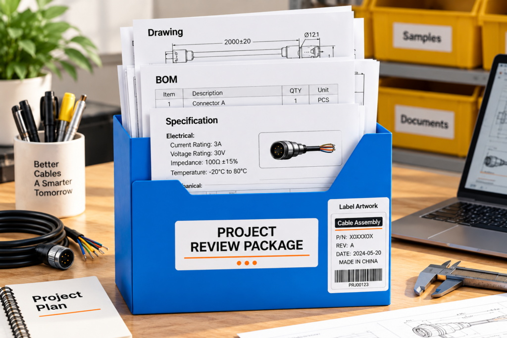
The strongest RFQ package combines a controlled drawing, BOM, connector references, pinout or wiring diagram, and project specification. When those documents are incomplete, sample photos, connector close-ups, cable length, application information, and target quantity can still support an initial review. Controlled files should carry clear revisions so everyone knows exactly which cable configuration is being priced.
| RFQ File | Useful Content | Main Purpose |
| 2D drawing | Dimensions, tolerances, connectors, orientation | Defines physical assembly |
| BOM | Cable, connectors, terminals, accessories | Defines materials |
| Pinout | Connector pins and conductor mapping | Defines electrical connection |
| Schematic | Circuit relationships | Clarifies complex wiring |
| Sample photos | Product and connector close-ups | Supports early identification |
| Datasheets | Exact connector/component data | Reduces sourcing mistakes |
| Packaging file | Labels, barcodes, carton marks | Defines delivery format |
| Specification | Electrical, environmental and test requirements | Defines acceptance basis |
Drawing and Dimensions
A useful cable drawing should allow someone unfamiliar with the project to understand the physical assembly without searching through several email threads. It should identify overall cable length, measurement reference, tolerances, connector names or part numbers, cable specification, connector orientation, strip lengths, branch dimensions where applicable, heat-shrink positions, label locations, sleeves, molded sections, and other controlled features.
Clarity matters more than visual complexity. A simple two-dimensional drawing with precise dimensions and connector references may be more valuable for quotation than an attractive 3D model that lacks manufacturing information. When complete drawings are available, Cablivo’s documented review scope can include cable length, connector type, wire gauge, pinout, wire sequence, material, labeling, testing, and packaging information before quotation or sampling. The drawing therefore becomes a working engineering reference that connects quotation, sample development, production preparation, and inspection.
BOM and Part Numbers
The BOM defines the components that make the assembly reproducible. Depending on the project, it can include the bulk multi-conductor cable or custom cable specification, connector housings, contacts, terminals, ferrules, heat-shrink tubing, sleeves, boots, clips, molded materials, labels, packaging items, and customer-controlled accessories.
Part numbers are especially important for connectors and terminals. A BOM entry that says “6-pin connector” can correspond to many different products, while a manufacturer name, connector series, housing number, terminal number, and approved-equivalent policy provides a much stronger sourcing basis. It can also be useful to identify whether a part is customer-nominated, no-substitution, equivalent-permitted, manufacturer-proposed, or customer-supplied. Cablivo’s factual project process includes BOM review covering connector models, terminals, wire specifications, materials, labels, packaging items, and possible sourcing risks before quotation or sampling.
Pinout and Reference Samples
For a multi-conductor assembly, the pinout should normally be a controlled engineering reference rather than a sentence buried in an email. It can appear on the drawing, in a separate table, or within an electrical schematic. The important point is that every conductor can be traced from one termination to the other.
A useful pinout table can list connector cavity, conductor color or wire number, opposite-end cavity or termination, conductor gauge if mixed, and circuit function. When an existing cable is being replaced or reproduced, reference photos can also support early review. The most useful image set normally includes the full cable, both connectors from several angles, connector faces, labels, molded sections, cable markings, and packaging when packaging replication is required. Photos cannot reliably reveal hidden pinout, conductor gauge, terminal part number, internal material, or conductor construction, so a physical sample or additional documentation may still be needed.
Revision Control
Every quotation should be linked to identifiable revisions of the drawing, BOM, pinout, specification, and packaging file. Revision control can appear administrative until one supplier prices Revision A while another is reviewing Revision C. If one revision changes the cable from 1.0 meter to 1.2 meters, replaces a connector, or modifies the wiring map, the two prices no longer represent the same assembly.
| File | Example Revision Control | Minimum Content to Confirm |
| Assembly drawing | DWG-001 Rev C | Dimensions, connectors, cable structure |
| BOM | BOM-001 Rev C | Materials and part numbers |
| Pinout | PIN-001 Rev B | Pin-to-wire mapping |
| Specification | SPEC-001 Rev A | Electrical and environmental requirements |
| Packaging file | PKG-001 Rev B | Label and carton requirements |
| Change record | ECN/ECR reference | Changes from previous revision |
The exact file-naming system is less important than traceability. When a new revision is issued during quotation, explain what changed instead of simply sending another PDF with a similar filename. That allows affected cost elements and engineering assumptions to be reviewed efficiently and reduces the risk of obsolete information carrying forward into sample development or later production.
How Do Quantity, Testing, and Delivery Affect the Quote?
A technically correct cable can still be quoted inaccurately when quantity, quality scope, packaging, or delivery assumptions are unclear. Provide sample requirements, initial production quantity, expected repeat volume when known, required inspections and tests, acceptance criteria, label and packaging instructions, expected project milestone, and shipping destination so the quotation reflects the real production and delivery scope.
| Commercial or Quality Input | What to State | Why It Matters |
| Sample requirement | Quantity and validation purpose | Defines development stage |
| Initial order | Planned production quantity | Affects purchasing and setup |
| Repeat demand | Forecast when known | Supports supply planning |
| Electrical tests | Required checks | Defines inspection scope |
| Mechanical tests | Pull, bend or other requirements | Adds testing work |
| Acceptance criteria | Limits or customer specifications | Makes test results meaningful |
| Labels | SKU, barcode, wire number, batch data | Affects identification |
| Packaging | Bulk, bags, boxes, kitting | Affects materials and labor |
| Timeline | Required milestone | Supports planning |
| Destination | Shipping country or location | Supports export planning |
Quantity and Project Stage
Quantity should describe both the current project stage and the expected commercial context. A development project may initially need only a small number of samples for fit and functional evaluation, while the production program could later require hundreds or thousands of units. The first production order may also be smaller than a mature repeat-order quantity.
For many Cablivo custom cable projects, the documented MOQ starts from 500 pieces, while the final MOQ depends on connector type, cable structure, materials, overmolding, tooling, packaging, and order quantity. The more useful quotation question is therefore not simply “What is your MOQ?” but “What quantity are we evaluating for this exact construction?” A special connector, custom-extruded cable, unique color, dedicated mold, or packaging component may introduce its own supplier minimum and affect the practical order level.
| Project Stage | Quantity Information | Main Quotation Purpose |
| Engineering sample | Sample quantity | Validation planning |
| Pilot/first order | Initial production quantity | Material and process preparation |
| Regular order | Expected batch size | Repeat production planning |
| Forecast | Approximate future demand | Supply discussion |
| Multi-SKU program | Quantity by SKU | Prevents volume assumptions |
Forecasts do not need to become firm purchase commitments. Their main value is helping the manufacturer understand whether the project is an early prototype, a first production order, or a long-term supply program.
Testing and Acceptance Criteria
Testing should be connected to a real product risk instead of becoming a generic checklist. Continuity and wire-sequence verification are often important for multi-conductor assemblies because one incorrectly connected conductor can make the entire cable unusable. Depending on the application, the project may also require insulation, Hi-Pot, pull-force, connector-fit, dimensional, bending, tensile, appearance, label, packaging, or other functional and environmental checks.
| Test or Check | What It Verifies | Useful Acceptance Reference |
| Continuity | Correct electrical path | Approved pinout |
| Wire sequence | Correct conductor mapping | Wiring table |
| Hi-Pot/insulation | Insulation behavior | Project specification |
| Pull force | Terminal/joint retention | Defined force or standard |
| Dimensions | Cable lengths and locations | Drawing tolerance |
| Connector fit | Mechanical mating | Approved mating connector |
| Appearance | Workmanship and finish | Approved sample/criteria |
| Label check | SKU and identification | Approved label data |
The acceptance criterion matters as much as the name of the test. “Pull test required” does not define the force, sample method, or pass/fail rule. “Continuity test” needs an approved pinout, while dimensional inspection needs a target dimension and tolerance. Cablivo’s documented test directions include continuity, insulation, Hi-Pot, pull force, bending, tensile, connector-life, connector-fit, pinout, wire-sequence, appearance, labeling, packaging, quantity, and pre-shipment inspection according to the product and project requirements. The same source explicitly states that these tests should not be presented as automatically applicable to every cable.
Packaging and Identification
Packaging becomes part of the cable specification when the product feeds a production line, warehouse, distributor, multi-SKU inventory system, ecommerce channel, or private-label program. The RFQ should identify whether the order requires bulk packing, individual bags, industrial packaging, retail boxes, kitting, connector protection, wire-number labels, customer SKU labels, barcode labels, batch identification, insert cards, or custom carton marks.
The packaging method can also affect product protection. Exposed terminals, keyed connectors, threaded interfaces, locking mechanisms, or delicate mating surfaces may need additional protection during shipping. Multiple cable lengths or connector variants increase the importance of clear SKU identification because receiving and warehousing errors can become more expensive than the packaging itself. Cablivo’s documented packaging capabilities can include private-label packaging, barcode labels, carton marks, wire-number labels, batch labels, multi-SKU packaging, kitting, and export-carton planning according to the project and channel requirements.
Timeline, Delivery, and Quote Stability
Expected timing should identify the milestone that actually matters. “Need delivery in two weeks” can refer to sample completion, pilot production, mass-production completion, shipment departure, or arrival at the final destination. These milestones are not interchangeable. Connector sourcing, cable material preparation, tooling when required, sample approval, test requirements, packaging files, order quantity, and document revisions can all influence the real schedule.
Cablivo’s documented content boundaries specifically state that lead time depends on product structure, material availability, connector sourcing, tooling requirements, order quantity, testing requirements, and packaging plan rather than using a fixed universal production promise. Shipping destination should also be supplied because it provides context for export packaging, documentation, target-market considerations, and delivery coordination.
Before the RFQ is finalized, it is worth checking that the drawing revision, BOM revision, conductor count, AWG, cable length, insulation, jacket, unshielded construction, connector part numbers, terminals, pinout, application, voltage, current, quantity, test scope, labels, packaging, timeline, and shipping destination all agree with one another. If two competent manufacturers can still choose materially different connectors, conductor gauges, materials, inspection scopes, or packaging methods without contradicting the RFQ, the request probably still contains hidden assumptions.
A complete production drawing is not always necessary for the first discussion. When documentation is still developing, customers can begin with sample photos, connector photos, cable length, application information, and target quantity so the missing requirements can be identified before quotation or sampling. The objective is not to remove every engineering question before contact. It is to expose the questions that can materially change price, fit, function, testing, or production before those changes become expensive.

Start Your Unshielded Multi-Conductor Cable Assembly RFQ With Cablivo
If you are developing, replacing, or sourcing an unshielded multi-conductor cable assembly, you do not need to wait until every document is perfect before beginning the technical discussion. A strong starting package can include your drawing, BOM, sample photos, connector model, cable length, conductor count, AWG, pinout, wire sequence, voltage and current requirements, application, target quantity, testing requirements, packaging plan, expected timeline, and shipping destination. These details give the engineering and production teams enough information to identify gaps before those gaps become quotation or sample problems.
Cablivo is the overseas-facing brand of Shenzhen Tianxiaowei Electronics Co., Ltd., a Shenzhen-based custom cable, wire harness, and cable assembly manufacturer with 18 years of industry experience, more than 20,000 square meters of factory space, a team of more than 1,500 people, and three manufacturing bases. Its documented project scope includes requirement review, drawing review, BOM review, connector confirmation, wire-sequence and pinout review, material selection, sample development, mass-production preparation, testing, packaging, labeling, and shipment coordination.
For multi-conductor projects, the manufacturing process can include cable preparation, multi-core stripping, terminal crimping, soldering, connector assembly, electrical and functional inspection, labeling, packaging, and later production steps according to the approved specification. The company’s documented production system includes multi-core processing equipment and assembly resources intended to support custom cable and wire-harness production from preparation through finished assembly.
If your documentation is already complete, send the drawing, BOM, pinout, connector references, and target quantity so the project can be reviewed against a controlled specification. If you only have an existing sample, prototype, or early-stage design, start with clear overall photos, connector close-ups, cable length, application conditions, and quantity information. The missing details can then be identified before the quotation or sample is treated as final.
The most useful RFQ is not necessarily the one with the most pages. It is the one that removes the assumptions most likely to change the cable. Send Cablivo your drawing, BOM, sample photos, connector information, cable requirements, and target quantity to begin an engineering review for your custom unshielded multi-conductor cable assembly.



