 Skip to content


A multi-conductor cable assembly quote should not be a price attached to a collection of assumptions. Two assemblies can look nearly identical on a purchasing screen yet use different conductor sizes, insulation systems, shielding structures, connectors, terminal arrangements, pinouts, strain-relief designs, tests, packaging methods, and production processes. That is why a request such as “quote a two-meter 12-core cable” may be enough for a rough discussion, but rarely enough for a dependable production quotation. The real objective is to define the assembly clearly enough that the engineering team, procurement team, manufacturer, quality department, and eventual production line are all discussing the same product.
To quote a multi-conductor cable assembly accurately, provide the drawing or sample reference, cable length, conductor count and AWG, conductor and jacket requirements, shielding structure, connector or terminal part numbers, pinout and wire sequence, application conditions, required tests, prototype and production quantities, labeling, packaging, and expected delivery requirements. If some details are unknown, identify them as open items instead of allowing suppliers to make different assumptions.
That distinction becomes important the moment several suppliers are compared. Imagine three manufacturers receiving the same short inquiry. One assumes an unshielded PVC cable with readily available connectors. Another assumes braided shielding and customer-specified terminals. A third includes a special jacket, molded strain relief, continuity testing, individual labels, and export packaging. The quotations may differ significantly, but the difference does not necessarily mean that one factory is expensive and another is cheap. It may simply mean that the factories have priced three different products under the same project name. A strong RFQ removes those hidden differences before price comparison begins.
What Files Are Needed for a Quote?
An accurate multi-conductor cable assembly quote normally starts with a controlled technical reference: a drawing, BOM, pinout or wiring diagram, and any sample information that explains the intended design. If a complete drawing is unavailable, clear sample photos, connector details, cable length, application information, and target quantity can still establish a practical starting point. The goal is to give the manufacturer one consistent technical reference instead of several disconnected descriptions.
Drawing and Sample Reference
A drawing is valuable because it gives engineering, sourcing, production, and quality teams one common definition of the assembly. It should make clear where the cable begins and ends, how overall length is measured, where branches are located, how connectors are oriented, and where labels, sleeves, heat-shrink tubing, molded sections, or other components are positioned. The drawing does not need to look like a marketing document. It needs to answer the practical questions that determine whether the finished cable will fit, connect, route, and function correctly in the intended equipment.
A physical sample becomes especially useful when a project involves replacing an existing supplier, reproducing an older cable, modifying an assembly that was never documented properly, or developing a similar product from an existing reference. In those cases, photographs should show more than the overall appearance. Useful images include both connector faces, cable markings, label placement, branch points, molded areas, strain-relief details, wire exits, and any packaging elements that form part of the approved product. If a physical sample can later be supplied, the photographs help the manufacturer decide what additional information should be collected before engineering review.
When neither a released drawing nor a physical sample is available, the project does not necessarily have to stop. A manufacturer can often begin by reviewing connector photographs, approximate cable length, conductor count, application details, target quantity, and known electrical requirements, then identify which technical items still need confirmation. This approach is more reliable than forcing an early quotation from incomplete data because it separates known requirements from assumptions before sampling, sourcing, or tooling decisions begin.
BOM and Part Numbers
The BOM should identify the parts that materially affect the product or price. For a multi-conductor cable assembly, this may include the bulk cable, individual wires, connector housings, contacts, terminals, seals, backshells, sleeves, heat-shrink tubing, protective braiding, overmold material, labels, clips, protective caps, fasteners, and packaging items. If a customer-approved component must be used, the exact manufacturer and part number should be listed rather than replaced by a generic description such as “8-pin connector” or “industrial terminal.”
This matters because two components that look similar in a photograph may differ in contact system, keying, plating, locking method, sealing design, allowable wire range, cable-entry diameter, or mating interface. A supplier may be able to recommend an alternative, but that alternative should be treated as a controlled engineering proposal rather than quietly incorporated into the quotation. The same principle applies to cable materials. If a drawing requires a specific cable construction or approved material, that requirement should be stated. If equivalent materials are acceptable, the RFQ should define which performance and compatibility conditions still need to be met.
A practical BOM also distinguishes customer-controlled components from items the manufacturer is allowed to select. That makes quotation comparison easier because procurement teams can see whether suppliers are pricing the same connector, cable, terminal, label, and packaging scope. It also helps identify sourcing risks early. A connector with an unusually long supply cycle, a low-volume special jacket, or a customer-specific terminal may have a larger effect on schedule and MOQ than the cable assembly process itself.
Lengths and Tolerances
Cable length should be defined using clear measurement points. A statement such as “1000 mm overall length” can still be interpreted differently depending on whether the measurement runs from mating face to mating face, cable exit to cable exit, molded body to molded body, or along the free cable between two connectors. Multi-branch assemblies require even more clarity because each leg may have a different length, tolerance, measurement datum, label position, or breakout location.
Tolerances should reflect actual installation requirements rather than being made unnecessarily tight everywhere. A dimension that determines whether a connector reaches a fixed mounting point may require closer control than a label location with generous clearance. On the other hand, leaving a critical breakout length, exposed conductor length, stripped length, or branch dimension undefined can cause installation problems even when the total cable length is correct. Tight tolerances also influence inspection and processing effort, so they should have a practical reason.
In production, dimensional control affects more than cutting. It influences stripping, crimping, soldering, connector assembly, overmolding, heat-shrink placement, branch formation, label location, and final inspection. Automatic cutting and multi-core stripping equipment can help control repeatability, but production equipment cannot correct an unclear measurement definition. The engineering drawing still needs to establish what is being measured and how that dimension relates to the final installation.
Pinout and Wiring Definition
A multi-conductor cable assembly cannot be defined accurately by connector part numbers alone. The manufacturer needs to know how every relevant conductor is routed from one termination point to another. A useful pinout table normally identifies the source pin, wire number or color, destination pin, and any special instruction such as twisted pair, shield drain, jumper, splice, grounded shell, unconnected conductor, or shared termination.
Straight-through wiring should never be assumed unless the project documentation says so. The same is true for shield termination. A cable may use a drain wire connected to a dedicated terminal, a braid bonded to a connector shell, a shield terminated at one end only, or another configuration defined by the equipment design. These differences can affect preparation, labor, component selection, inspection, and functional performance, even when the outside appearance of the cable remains unchanged.
Pinout errors are particularly costly because a completed cable may look completely correct while failing when it is connected to equipment. That is why connector confirmation, wire-sequence review, and pinout verification should be treated as part of engineering preparation rather than as a final inspection detail. A clear wiring reference also makes production testing easier because the expected electrical path is defined before test fixtures or inspection procedures are prepared.
| RFQ File or Reference | Minimum Useful Information | Typical Example | Quotation Risk If Missing |
| Assembly drawing | Length, measurement points, branches, connector orientation, labels | 1500 mm mating-face to mating-face with two breakouts | Different suppliers may price different layouts |
| BOM | Cable, connectors, contacts, terminals, sleeves, labels | Connector P/N, terminal P/N, cable specification | Components may be priced using different assumptions |
| Pinout table | Source pin, conductor ID, destination pin | A1 → Red → B3 | Wiring differences may make samples unusable |
| Sample photos | Full assembly, connector details, labels, molded areas | Front/rear connector views plus overall image | Hidden construction details may be missed |
| Test specification | Required checks and acceptance criteria | Continuity, insulation or pull force where required | Test cost may be excluded or misunderstood |
| Packaging file | Bag, label, barcode, carton, protective method | Individual bag plus customer part-number label | Delivered scope may differ from quotation |
The strongest RFQ package is not necessarily the package with the greatest number of documents. It is the package in which the drawing, BOM, pinout, sample, test requirement, and packaging information describe the same product without contradicting one another.
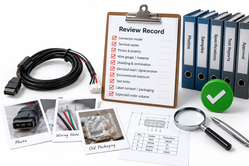
Which Cable Construction Details Matter?
The cable construction should define what is inside the jacket, not simply the number of visible cores. Conductor count, AWG, conductor structure, insulation, pair arrangement, shielding, jacket requirements, identification method, and finished diameter can all influence electrical behavior, flexibility, termination, component compatibility, manufacturability, and cost. The correct construction depends on the application rather than on one standard multi-conductor cable design.
Conductor Count and Circuit Function
Start by defining what the conductors actually do. An eight-conductor cable may contain eight independent control circuits, four twisted signal pairs, six signal wires plus two power conductors, or another combination. Those products can have the same conductor count while requiring different internal geometry, insulation, shielding, termination, and quality-control methods. A quotation based only on the number of cores therefore leaves too much room for interpretation.
For mixed-function assemblies, it is useful to group conductors according to circuit purpose. Power conductors may require a different gauge from signal or control conductors. Sensitive signal paths may need twisting or shielding that is unnecessary for basic control lines. Some conductors may be reserved for future equipment functions, while others may connect to a common ground or shield structure. Explaining these functions gives the manufacturer context for reviewing the proposed construction instead of treating all cores as identical wires.
A common RFQ mistake is to specify only “12-core cable” and expect every supplier to reach the same internal design. That may be acceptable for an early budget estimate, but it is not enough for a production quotation intended for supplier comparison. Clear circuit grouping reduces unnecessary overdesign while also preventing a low-cost quotation based on a structure that cannot support the application.
AWG and Conductor Structure
Wire gauge should be defined by circuit group whenever the assembly does not use one uniform conductor size. A hybrid cable may use larger conductors for power and smaller conductors for control, sensor, or communication functions. If all conductors use the same AWG, that should also be stated explicitly. This helps the manufacturer evaluate conductor material, terminal compatibility, cable diameter, flexibility, and processing requirements from the same technical basis.
Stranding also matters because conductor construction affects flexibility, handling, termination, and production consistency. A cable installed permanently inside equipment may have different mechanical priorities from one that moves repeatedly or is handled during every operating cycle. When flexibility is important, conductor strand construction should be reviewed alongside jacket material, cable diameter, bend behavior, and strain relief rather than treated as an isolated specification.
Selecting a larger conductor does not automatically make a design better. Larger AWG requirements can increase cable diameter, terminal size, stiffness, connector constraints, and material cost. The most useful approach is to define the electrical and mechanical conditions first, then use them to review an appropriate conductor structure rather than adding material without a clear application reason.
Shielding and Pairing
Shielding should be treated as an engineering requirement, not as a universal quality upgrade. A multi-conductor cable may require no shield, an overall foil shield, braided shielding, foil plus braid, individually shielded pairs, or another structure depending on the electrical environment. Adding shielding may increase material usage, cable diameter, preparation steps, termination work, and inspection requirements, so the quotation should make clear which shield structure is actually needed.
Pairing deserves similar attention. Twisted conductors may be required when specific signals, communications, or noise-control requirements depend on maintaining a defined relationship between conductors. If the cable contains specified twisted pairs, the RFQ should identify exactly which conductors belong together. Otherwise, two manufacturers may produce internally different cables while both believing that they have followed the same basic conductor-count specification.
Shield termination is another critical detail. The manufacturer needs to know whether a drain wire connects to a dedicated pin, whether the braid bonds to a connector shell, whether a shield continues through both ends, or whether it is intentionally terminated at one end only. Foil removal, braid preparation, soldering, and connector assembly can all change depending on this detail, so it should be visible in the drawing or wiring documentation.
Jacket, Identification and Diameter
Jacket selection should begin with the actual environment and handling requirement. Relevant questions include whether the cable must remain flexible, withstand repeated handling, resist abrasion, operate around oil or chemicals, tolerate outdoor conditions, maintain a particular surface feel, fit inside a restricted cable path, or support a specified color. A material name alone may not describe these conditions clearly enough because formulations within one material family can have different characteristics.
Materials such as PVC, TPE, TPU, PUR, silicone, PE, XLPE, and related insulation or jacket systems may all be discussed in custom cable projects, but material performance should be evaluated according to the application, target market, expected environment, and test requirements. Specific temperature, oil-resistance, flame, medical, or compliance claims should only be tied to actual material documentation and project requirements rather than assumed from the material family name.
Finished diameter also deserves early attention when the cable has to pass through a gland, backshell, grommet, enclosure opening, routing channel, strain-relief feature, or existing machine interface. Conductor count, AWG, insulation thickness, shielding, fillers, pair arrangement, and jacket thickness all contribute to the final diameter, so the OD should be reviewed as part of the complete construction rather than treated as a cosmetic afterthought.
| Construction Variable | Example Project Definition | Main Engineering Effect | Procurement Value |
| Conductor count | 12 independent cores | Defines internal cable structure | Prevents pricing different core arrangements |
| Hybrid circuit | 2 power + 6 signal conductors | May require different gauges or grouping | Improves technical comparison |
| AWG | AWG 18 power, AWG 24 signal | Affects conductor material and terminals | Makes cost comparison more meaningful |
| Pairing | 3 defined twisted pairs | Changes internal cable formation | Prevents missing or unnecessary pair construction |
| Shielding | Overall foil plus drain wire | Adds shielding and termination processes | Makes shield cost visible |
| Jacket requirement | Flexible jacket for moving equipment | Influences material and handling | Reduces unsuitable low-cost substitutions |
| Finished OD | Must fit a 9 mm cable entry | Limits complete cable build | Reduces late mechanical redesign |
| Core identification | Numbered or color-coded conductors | Supports wiring and inspection | Improves assembly and field service |
The practical value of defining cable construction is simple: the more clearly the internal structure is controlled, the more likely different manufacturers are to quote the same technical product rather than several loosely similar cables.

What Termination Details Are Required?
Termination information should define the exact connector or terminal, conductor-to-pin relationship, connector orientation, shield termination, and any molded or strain-relief structure. These details often determine whether the assembly fits and functions correctly. A cable can have the correct length, conductor count, and materials and still fail completely if the connector keying, contact system, pinout, shell orientation, or cable exit direction is wrong.
Connector and Terminal Selection
Use exact manufacturer part numbers whenever a specific connector housing, plug, receptacle, contact, terminal, backshell, seal, or accessory is controlled by the project. Mating-part information is also helpful when interface compatibility needs to be checked. If alternatives are permitted, the RFQ should explain which electrical, mechanical, material, and installation characteristics must remain equivalent so that proposed substitutions can be reviewed before sampling or production.
This is particularly important with industrial connectors because small differences can be difficult to identify from a catalog image. One connector family may contain several keying options, pin counts, contact systems, cable-entry sizes, sealing structures, locking styles, or termination methods. A description such as “8-pin waterproof connector” may therefore refer to many unrelated products that cannot be exchanged without reviewing the equipment interface.
Connector accuracy is one of the most basic controls in a custom cable project. A wrong model, incorrect male/female configuration, incompatible mating part, wrong pin count, or reversed connector direction can make a sample unusable even when the cable itself has been manufactured correctly. Engineering review should therefore verify connector details before material purchasing and sample assembly become expensive to change.
Wire Sequence and Pinout
Every conductor that matters to product function should have a controlled destination. A practical wiring table can identify Side A pin, conductor ID, color or wire number, Side B pin, and any notes regarding twisted pairs, drain wires, shielding, grounds, splices, jumpers, or unused positions. Complex harnesses may require a schematic or wire map, but the goal remains the same: another technician should be able to understand the electrical path without relying on verbal explanation.
Wire color should support identification, but it should not replace a controlled electrical definition unless the drawing intentionally uses color as the master reference. Production teams need a repeatable relationship between conductor, circuit, and termination point. This becomes especially important when the project moves from an engineering sample to repeated production because informal instructions are more difficult to control across multiple operators and production batches.
Wire-sequence errors are risky because the completed assembly can look correct during visual inspection while still failing inside the customer’s equipment. Confirming wire sequence and pinout before sampling also improves test planning because the expected electrical relationships can be programmed into continuity or functional test fixtures rather than discovered after the first assembly has already been built.
Orientation and Cable Exit
Connector orientation is a mechanical requirement, not simply a presentation preference. Right-angle connectors, keyed circular connectors, molded plugs, panel interfaces, and equipment with restricted installation space may all require specific clocking. A connector rotated by 90 degrees may mate correctly but force the cable into an impossible routing path, interfere with nearby components, or place excessive stress on the cable exit.
A drawing should show orientation in a way that does not depend on vague descriptions such as “left side” or “upward.” Useful references include connector mating-face views, key positions, clock references, datums, dimensioned side views, or annotated sample photographs. Cable exit direction should be controlled in the same way when the cable exits a molded body, backshell, boot, or strain-relief structure at a defined angle.
For molded assemblies, these requirements should be frozen before tooling is finalized. Changing connector orientation or exit direction after the mold has been produced can affect tooling, appearance, assembly, and schedule. The approved sample should therefore represent the final orientation that production is expected to repeat.
Overmolding and Strain Relief
Overmolding can add strain relief, connector protection, a controlled cable exit, sealing features, or a defined branded appearance. Because it changes both the manufacturing process and the finished mechanical interface, it should be discussed during RFQ preparation rather than added after the initial price has been accepted. A quote for a simple assembled connector and a quote for a custom molded termination are not directly comparable.
Useful input includes the desired overmold shape, connector orientation, cable diameter, cable exit, material, color, logo requirement, surface appearance, protection requirement, and any project-specific mechanical or sealing expectation. If new tooling is needed, the quotation should separate tooling or development cost from production unit cost so procurement teams can understand which costs are one-time and which continue through every production order.
The sample stage is particularly important for molded assemblies because appearance, connector fit, strain-relief geometry, cable exit, insertion clearance, and surface quality can be reviewed before mass production. Once the final sample, tooling status, material, orientation, and relevant tests have been approved, the same controlled specification can be used for production preparation.
| Termination Item | What Should Be Specified | Example | Main Risk If Undefined |
| Connector | Manufacturer and exact part number | Customer-approved 12-pin plug | Wrong mating interface |
| Terminal/contact | Exact contact where controlled | Contact matched to specified AWG | Incorrect crimp or fit |
| Pinout | Point-to-point wiring | Pin 1 → White → Pin 5 | Functional failure |
| Shield termination | Pin, drain, shell, one or both ends | Braid bonded to shell | EMI or wiring mismatch |
| Orientation | Keying or clocking reference | Key at 12 o’clock | Installation interference |
| Cable exit | Straight or defined angle | 90° exit toward enclosure wall | Mechanical fit problem |
| Overmold | Shape, color, material, logo requirement | Black strain-relief overmold | Tooling and cost differences |
| Tooling status | Existing or new tool | New mold required | Hidden one-time cost |
Termination details often create more project risk than the cable jacket itself because they are where electrical, mechanical, connector, tooling, and installation requirements come together. Defining them early makes both the quotation and the eventual sample more useful.

What Application and Test Requirements Apply?
Application information explains what the cable must do after it leaves the factory. The manufacturer should understand the electrical function, movement, installation environment, mechanical exposure, and required verification. The test plan should then reflect those real risks. Continuity, insulation, pull-force, flexing, dimensional, environmental, or functional checks may be relevant depending on the project, but adding every available test to every cable does not automatically create a better product.
Electrical and Functional Requirements
Describe what each circuit does rather than supplying only cable diameter and connector information. Useful input may include whether individual conductors carry power, control signals, sensor signals, communications, or mixed functions. Where relevant, provide the customer-controlled voltage, current, grounding arrangement, signal requirement, or other electrical conditions that influence conductor size, insulation, shielding, termination, or test planning.
The supplier does not need every confidential detail of the final machine to understand the cable. The purpose is to explain the technical conditions that materially affect the assembly. If some electrical requirements are still being developed, they should be identified as open engineering items rather than allowing each supplier to make its own assumption. This makes later design changes easier to track and prevents a provisional quotation from being mistaken for a final production specification.
Functional acceptance should also be discussed early. Some assemblies may only require point-to-point continuity verification, while others may need to operate with a test fixture, mating connector, device interface, or customer-defined functional procedure. Knowing the expected acceptance method helps determine whether test fixtures, additional assembly steps, or project-specific validation should be included in the quotation.
Movement and Mechanical Use
The same multi-conductor cable can experience very different stress depending on where it is installed. A cable mounted inside a stationary electrical cabinet may move only during maintenance, while a cable connected to a sensor, handheld controller, door, automated mechanism, moving fixture, or frequently serviced component may bend repeatedly throughout its life. Those applications should not automatically use the same conductor and jacket structure.
Tell the manufacturer whether the cable remains static, moves occasionally, flexes repeatedly, follows moving equipment, experiences pulling during installation, or is exposed to vibration. These conditions can influence conductor stranding, jacket selection, minimum bend considerations, routing, strain-relief design, connector protection, and whether mechanical validation is appropriate. The information is more useful when it describes actual movement rather than simply requesting a “flexible cable.”
Mechanical testing should be linked to the real application. Repeated bending or swing testing may be useful for selected flexible cable projects, while terminal pull-force testing may be more important where crimp retention is the primary concern. The presence of a testing machine in a factory does not mean every cable should undergo that test. The project should determine which failure modes need to be evaluated.
Environment and Material Exposure
The phrase “industrial application” is too broad to define a cable. One industrial assembly may operate permanently inside a clean cabinet, while another is exposed to oil, coolant, outdoor moisture, temperature changes, corrosion, vibration, abrasion, or electrical interference. Describing the actual installation environment helps the manufacturer understand which material, shielding, connector, strain-relief, or protective features require attention.
Useful RFQ information can include temperature conditions, humidity, oil or chemical exposure, abrasion, outdoor use, corrosion concerns, vibration, electromagnetic interference, and sealing requirements. A cable that passes through a machine enclosure may also face very different conditions along its length, so critical local exposure around connectors, moving sections, or cable exits should be explained where relevant.
Material claims should remain project-specific. A jacket family should not automatically be described with an exact temperature, oil-resistance, flame, medical, or compliance rating unless the actual selected material and supporting documentation confirm it. A more reliable approach is to describe the required environment first, then select and verify materials against the project specification.
Testing and Acceptance
Testing should reflect the failure modes that matter to the assembly. Continuity or wire-map testing can help detect opens, shorts, and incorrect wiring. Hi-pot or insulation testing may be relevant when electrical insulation performance must be verified. Pull-force testing may be used where terminal retention or joint strength matters. Dimensional and visual inspection help confirm fit, orientation, label position, appearance, and mechanical requirements. Environmental or flex-related testing may be appropriate for projects exposed to those conditions.
The RFQ should describe not only the test name but also the acceptance criteria whenever possible. “Pull test required” provides limited information unless the connection under test and required force are defined by the project. An environmental test has the same issue if temperature, humidity, duration, or acceptance conditions remain unspecified. Test requirements become useful when they can be connected to a measurable customer requirement rather than used as general marketing language.
Quality planning is strongest when incoming inspection, in-process control, outgoing inspection, and project-specific testing work together. The approved sample, final drawing, BOM, pinout, materials, labels, packaging, and test requirements should become the reference for production. This reduces the risk that a cable passes an electrical test while still failing a mechanical, labeling, or installation requirement that was never included in the inspection plan.
| Application Condition | Information to Provide | Possible Design Impact | Test or Review to Consider |
| Static cabinet wiring | Limited movement, controlled environment | Standard flexibility may be sufficient | Continuity and dimensional inspection |
| Repeated movement | Bend location and movement frequency | Stranding, jacket and strain-relief review | Project-defined flex or swing test |
| Higher electrical load | Current and voltage requirements | Conductor gauge and insulation review | Electrical verification as specified |
| Signal-sensitive circuit | Signal type and interference environment | Pairing or shielding may be required | Wiring and shield review |
| Outdoor exposure | Moisture, temperature changes, UV or sealing need | Jacket and connector protection review | Environmental or sealing test if specified |
| Oil or chemical exposure | Substance and exposure conditions | Material compatibility becomes important | Customer-defined material validation |
| High retention requirement | Pulling or mechanical load | Crimp and strain-relief review | Pull-force test |
| Compliance-controlled project | Actual standard and target market | Material and document restrictions | Confirm required documentation |
The practical rule is straightforward: the cable should be quoted for the environment in which it will actually work, not merely for how it appears in a photograph or drawing.

What Quantity and Delivery Details Are Needed?
A complete RFQ should separate sample quantity from production quantity, identify realistic repeat demand when known, disclose custom tooling or special material requirements, define packaging and labeling, and state the expected schedule and delivery destination. These commercial details affect sourcing, material preparation, tooling economics, testing, packaging, and production planning, so they belong in the quotation discussion rather than being added after technical approval.
Sample and Production Quantities
Prototype quantity and production quantity serve different purposes and should be stated separately. Samples may be used for connector fit, equipment integration, electrical validation, handling evaluation, packaging review, internal approval, or customer testing. Production quantity determines how the manufacturer plans material purchasing, production setup, assembly, inspection, packing, and shipment. Mixing the two stages in one vague quantity can create confusion about pricing and preparation requirements.
If a project is expected to repeat, provide a realistic forecast when one exists. There is little value in creating an optimistic annual quantity simply to obtain a lower unit price because the quotation may then depend on purchasing assumptions that never occur. A more useful RFQ can state the immediate sample quantity, first expected production quantity, and estimated repeat-order range. That gives sourcing teams a more realistic basis for reviewing material, connector, and production requirements.
For many custom cable projects, MOQ can depend on connector type, cable construction, materials, custom extrusion, overmolding, tooling, packaging, and order quantity. A simple cable assembled from existing materials may have a different practical minimum from a project requiring a custom cable, special color, dedicated connector, or molded structure. MOQ should therefore be reviewed in relation to the actual assembly rather than treated as one universal number for every product.
Tooling and Special Materials
Custom tooling and special materials should be identified before the quotation is considered final. A project may require a custom overmold, unique strain-relief geometry, special jacket color, customer-controlled conductor construction, connector protection, unusual label material, private tooling, or another non-standard input. These requirements can create one-time development costs, material minimums, longer preparation periods, or additional sampling steps.
A strong quotation separates one-time costs from recurring production costs. Tooling, test fixtures, molds, or development charges should not be hidden inside a unit price if doing so makes supplier comparison difficult. Procurement teams should be able to see which costs apply only during project development and which remain part of every production order. This becomes especially important when evaluating suppliers for a long-term program.
Material availability should also be reviewed before delivery dates are promised. A custom jacket color, special connector, approved terminal, or customer-specific cable may have different purchasing conditions from common components. Identifying these factors during quotation allows the project team to decide whether the exact material is mandatory, whether an approved alternative is acceptable, or whether a larger purchasing quantity is required.
Packaging and Labeling
Packaging can be part of the product even when it does not affect electrical performance. A factory bulk-packed cable may require only organized bundles and carton identification, while a distributor, spare-parts program, production-line kit, branded accessory, or service component may need individual bags, labels, barcodes, customer part numbers, protective caps, inserts, cartons, or private-label files.
For connectors with exposed contacts, delicate latches, molded surfaces, or orientation-sensitive components, packaging also protects the product during handling and transport. The RFQ should therefore state whether protective caps, separators, trays, anti-scratch protection, specific winding methods, or other protection is required. Packaging should not be left until the day before shipment if it forms part of the approved customer specification.
Label content deserves the same control as a connector or cable length when customers use part numbers, revision codes, barcodes, or internal receiving systems. A technically correct cable delivered with the wrong label may still be rejected or create production-line confusion. Label files, packaging layout, carton requirements, and destination information should therefore be reviewed before bulk production is released.
Schedule and Delivery Basis
Instead of asking only for the “fastest lead time,” provide the project milestones that matter. These can include when engineering samples are needed, when internal verification will occur, when the production order is expected, and when finished goods are required at the destination. The schedule becomes much easier to evaluate when it is connected to actual technical and commercial events.
Lead time should reflect the product being built. A cable using available connectors and an existing construction may follow a different preparation path from one requiring new tooling, custom extrusion, special materials, customer-defined tests, or branded packaging. The same principle applies to imported or customer-specified connectors. Material availability may become the critical path even when assembly itself is straightforward.
The most reliable production schedule is normally confirmed after the sample, drawing, BOM, materials, quantity, testing, packaging, and order details have been sufficiently defined. This does not make the manufacturer slower; it makes the schedule more meaningful. A fixed delivery promise given before those items are known may look attractive during supplier selection but has limited value if the project later changes.
| Commercial Input | Example RFQ Value | Why It Matters | Procurement Check |
| Sample quantity | 10 engineering samples | Defines prototype material and setup | Confirm whether sample cost is separate |
| First production order | 1,000 pcs | Supports material and production planning | Compare suppliers at the same quantity |
| Repeat forecast | 2,000–5,000 pcs per release | Helps review sourcing strategy | Avoid overstating future volume |
| Tooling | New overmold tool required | Adds one-time development cost | Separate tooling from unit price |
| Special material | Customer-defined jacket color | May require material preparation | Confirm availability and minimums |
| Packaging | 1 pc/bag plus barcode label | Adds packing and inspection work | Include in every supplier quotation |
| Destination | Customer warehouse in Germany | Affects shipment planning | Compare quotations on the same basis |
| Required milestone | Samples before validation build | Influences project schedule | Confirm technical inputs early |
| Open items | Shielding requirement under review | May change final cost | Require assumptions to be listed |
Missing commercial details can make a quotation look much more precise than it actually is. If one manufacturer prices 500 pieces in bulk packaging, another prices 5,000 pieces with individual labels, and a third assumes customer-supplied connectors, their unit prices cannot be compared directly. A useful purchasing comparison uses the same drawing revision, technical scope, quantity, component responsibility, testing plan, packaging specification, tooling basis, and delivery condition.

What Should You Send Cablivo for a Multi-Conductor Cable Assembly Quote?
If your multi-conductor cable assembly project is ready for quotation, the most useful starting package is straightforward: provide the drawing, BOM, sample photographs if available, connector information, cable length, conductor count, AWG, pinout or wire sequence, application, target quantity, testing requirements, packaging plan, and shipping destination. If some of these details are still open, identify them clearly rather than filling the gaps with assumptions. An engineering review can then focus on the missing information that genuinely affects sample development, material preparation, tooling, testing, or production.
Cablivo is the overseas-facing website brand of Shenzhen Tianxiaowei Electronics Co., Ltd., a Shenzhen-based custom cable, wire harness, and cable assembly manufacturer supporting project work from requirement review, drawing review, material selection, and sampling through mass production, inspection, packaging, labeling, and shipment coordination. The manufacturing foundation supports conductor preparation, stranding, insulation and jacket processing, shielding-related work, multi-core cutting and stripping, crimping, soldering, connector assembly, overmolding, testing, labeling, packaging, and related project execution.
For engineering teams, the most valuable starting point is not a perfectly finished RFQ document. It is a technically honest one. If you have a complete drawing and BOM, they can be reviewed together with connector, pinout, material, testing, and packaging requirements. If you only have a physical sample, old supplier reference, connector photographs, or partial specification, those materials can still be used to determine which details need to be clarified before a production-level quotation is prepared.
For procurement teams, the objective is equally practical: make sure every manufacturer is quoting the same assembly. The lowest unit price has limited value if it excludes shielding, uses a different connector, assumes another cable construction, omits required testing, or ignores customer labeling and packaging. A well-prepared RFQ improves not only quotation accuracy but also the quality of supplier comparison, sample validation, and the eventual transition into repeat production.
Send your drawing, BOM, sample photos, connector details, pinout, cable specification, target quantity, testing requirements, and packaging plan to begin a multi-conductor cable assembly project review. Once the critical requirements are defined, the quotation can be built around the product you actually need rather than around assumptions that have to be corrected later.



