 Skip to content


An MPO-to-LC breakout fiber cable assembly can look deceptively simple on a purchase list: one MPO connector at one end, several LC connectors at the other, and a length in between. In reality, that short description can represent several very different assemblies. Fiber count, MPO gender, polarity, LC grouping, fiber type, overall length, breakout length, cable construction, application, optical-performance requirements, testing scope, labeling and packaging can all affect what should be supplied and what the quotation actually includes.
To quote an MPO-to-LC breakout fiber cable assembly accurately, the supplier needs the fiber count and fiber type, MPO interface and gender, LC configuration, polarity or fiber mapping, overall and breakout lengths, cable construction, application environment, optical and testing requirements, order quantity, labeling, packaging, and any available drawings, BOMs, samples or mating-equipment information.
The important point is that an accurate quotation is not only about reaching the correct unit price. It is also the first opportunity to prevent a specification mistake from reaching production. A cable can arrive with the right overall appearance and still fail the project because the MPO gender cannot mate with the equipment, the breakout legs are too short for the rack layout, the LC branches follow the wrong channel order, or the specified optical performance was never clearly included in the quotation. Those problems are far easier to correct while reviewing an RFQ than when installers are already standing in front of a live rack.
What Basic Cable Specifications Are Required for a Quote?
A useful MPO-to-LC quotation should begin with the physical definition of the assembly: fiber count, fiber type, overall cable length, breakout length, cable construction and installation conditions. These details establish what the cable actually is before connector polarity, optical testing or packaging are discussed. If any of them remain vague, two suppliers can quote two different products while both appear to be responding to the same inquiry.
Fiber Count and Fiber Type
Fiber count determines the basic breakout architecture and should always be stated explicitly. Common MPO configurations include 8, 12, 16 and 24 fibers, although the actual number required depends on the equipment and optical architecture. An eight-fiber assembly that uses every position can form four LC duplex pairs, while twelve fibers can form six duplex pairs and twenty-four fibers can form twelve. That arithmetic is straightforward, but the real project may not use every fiber position, which is why a fiber map is often more useful than a simple fiber-count statement.
The fiber type should also be identified independently. OS2 single-mode fiber commonly uses a 9/125 µm core/cladding geometry, while OM3 and OM4 multimode fibers use a 50/125 µm geometry. The correct choice should come from the optical modules, installed cabling system, transmission requirements or approved BOM rather than from jacket color or a similar-looking cable found online. If the fiber type is uncertain, supplying the transceiver or equipment model gives the engineering team a more reliable basis for review.
| Fiber Configuration | Typical Full LC Breakout | Common Project Context | Key RFQ Check |
| 8 fibers | 4 LC duplex pairs | Parallel optics and equipment breakout | Confirm whether all 8 fibers are active |
| 12 fibers | 6 LC duplex pairs | Structured cabling and distribution | Confirm polarity and channel use |
| 16 fibers | 8 LC duplex pairs | Higher-density parallel interfaces | Confirm MPO-16 interface requirement |
| 24 fibers | 12 LC duplex pairs | High-density backbone or distribution | Confirm ferrule and channel architecture |
| OS2 | Single-mode, 9/125 µm | Long-distance or single-mode systems | Match optics and installed network |
| OM3 / OM4 | Multimode, 50/125 µm | Data-center multimode links | Match transceivers and existing infrastructure |
Overall Length and Breakout Length
A description such as “5 m MPO-to-LC cable” may still be incomplete because two different dimensions usually matter. The overall assembly length determines whether the cable reaches between the required equipment locations, while the breakout length determines how far the individual LC branches can travel after the transition point. A cable can therefore have the correct total length and still be awkward or impossible to route inside the rack.
The drawing should make the measurement reference clear. Different organizations may measure an assembly between ferrule reference points, connector ends or another controlled location. The exact convention matters less than using the same convention for quotation, sample approval, inspection and repeat production. If the project has a defined length tolerance, place it directly on the controlled drawing. When no tolerance has been established, it is better to review a practical manufacturing tolerance than to leave the production team to infer one.
Breakout length deserves particular attention in high-density equipment. Four LC duplex pairs may need to reach four adjacent ports, different rows of ports or separate equipment zones. A simple rack photograph or port-layout sketch can often communicate that routing requirement faster than several emails.
Cable Construction and Jacket Requirements
The cable jacket is not simply a color or appearance choice. Construction can influence cable diameter, bend behavior, routing density, mechanical protection, environmental suitability and the way the assembly behaves during installation. A compact rack-level breakout cable and a more protected assembly used in a demanding installation may share the same MPO and LC connectors but require different cable structures.
When the project already specifies a jacket or environmental classification, include the exact requirement in the RFQ. LSZH, OFNR, OFNP or other ratings should only be requested when they are relevant to the actual installation, customer specification or applicable project requirements. Adding a higher specification without a real reason can increase cost and material constraints without adding practical value to the application.
Cable outside diameter can also be important in dense pathways. If the assembly must pass through a narrow conduit, cable manager or rack entry point, include that dimensional restriction. That allows the cable structure to be evaluated before a sample is produced rather than after the first assembly fails to fit the intended route.
Installation Conditions
Installation information gives the supplier a way to check whether the requested physical structure makes sense. Useful details include rack location, tray routing, pathway width, bend limitations, pulling conditions, connector protection needs and the amount of space available around the breakout transition. These are practical details that are often missing from purchase descriptions even though they directly affect whether the cable is easy to deploy.
A preterminated assembly that must pass through a narrow pathway may need more protection around the connector end than a cable that stays entirely inside a rack. A cable entering a dense switch area may need a more compact breakout arrangement than one connecting equipment across an open tray. The application description does not replace the drawing, but it provides a valuable cross-check between what has been specified and what the installation actually demands.
When engineering, procurement and installation teams all review the same dimensional and routing information, the RFQ becomes much more useful. It stops being a simple price request and becomes an early-stage check that the physical assembly can actually be installed as intended.
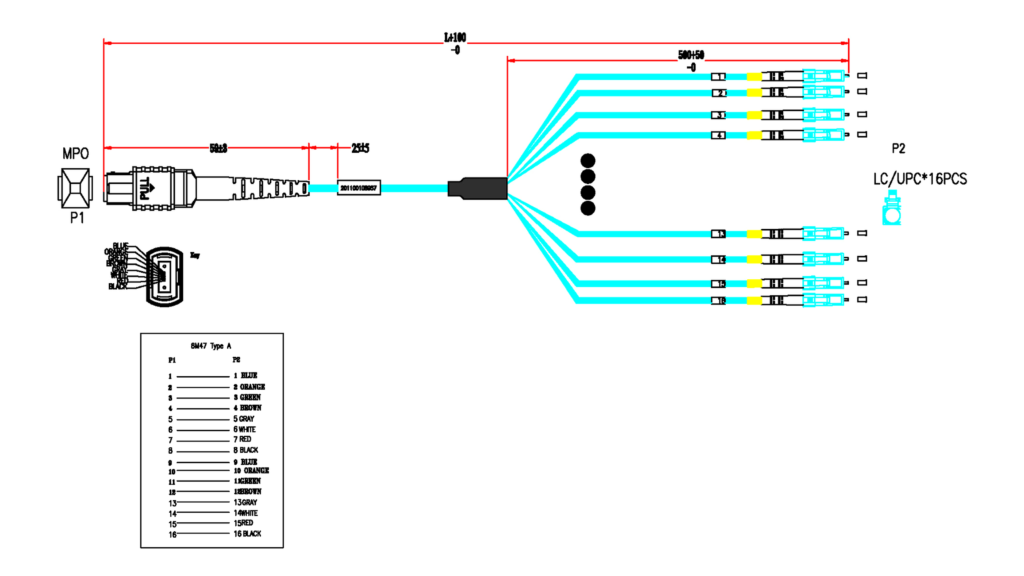
Which MPO and LC Connector Details Must Be Confirmed?
The connector specification needs to define far more than “MPO to LC.” The RFQ should confirm MPO fiber count, male or female gender, polish type, LC simplex or duplex arrangement, polarity and the exact fiber-to-channel relationship. These details determine whether the cable can physically mate with the intended equipment and whether every optical path reaches the correct LC connector after breakout.
MPO Gender and Interface
MPO gender refers to the alignment-pin arrangement. A male MPO connector is pinned, while a female MPO connector is unpinned. Because the mating relationship depends on which side carries the alignment pins, gender must be checked against the transceiver, adapter, cassette, panel or other component the cable will connect to. It is not a cosmetic option that can safely be selected after the quotation is approved.
Photographs alone are not always reliable because a pinned and unpinned MPO connector may appear very similar from a normal viewing angle. A better RFQ includes the required gender together with the mating equipment model, interface specification or a clear close-up reference. When the customer has already qualified a particular connector manufacturer or part number, that reference should also appear in the BOM or drawing.
The MPO fiber count must be confirmed at the same time. MPO-8, MPO-12, MPO-16 and MPO-24 configurations are not interchangeable descriptions of one universal interface. Their ferrule architecture and channel arrangement can differ, so the generic word “MPO” is not enough to define what should be quoted.
UPC or APC Polish
Connector polish is another field that should be stated directly rather than inferred from fiber type or connector color. UPC and APC interfaces use different end-face geometries and are selected according to the optical system and mating components. The correct polish should therefore come from the network design, equipment specification or approved existing assembly.
The MPO and LC ends should be treated separately when necessary. A customer may already know the MPO-side polish but have incomplete information about the LC side, or vice versa. Listing each end independently avoids the assumption that a requirement at one end automatically defines the other.
When replacing an existing assembly, an old product label, part number, high-resolution connector photograph and mating-device datasheet can be extremely helpful. Together, those references allow the physical interface to be checked against the documentation before a prototype is built.
| Connector Item | Common Options | What Should Be Verified | Main Risk if Incorrect |
| MPO gender | Male / female | Mating device or adapter | Connector cannot mate correctly |
| MPO fiber count | 8 / 12 / 16 / 24 | Equipment and lane architecture | Wrong physical interface |
| MPO polish | UPC / APC as specified | Existing optical system | Optical-interface mismatch |
| LC arrangement | Simplex / duplex | Port layout | Wrong breakout presentation |
| LC polish | UPC / APC as specified | LC mating interface | Compatibility or performance issue |
| Fiber mapping | Project-defined | Approved polarity map | Wrong optical channel assignment |
LC Breakout Arrangement
The LC side needs more detail than the connector family name. Confirm the number of LC connectors, whether they are grouped into duplex pairs, how duplex clips should be arranged and whether the branches require individual channel identification. An eight-fiber full breakout commonly produces four LC duplex pairs, but that does not automatically determine the label sequence or routing arrangement.
Physical port layout matters here. Some projects place all LC pairs together on one panel, while others route each branch toward a different module or device. That can change the required breakout length, label position and the way the branches are bundled or protected. If port spacing is tight, a drawing showing the equipment face can help the manufacturer understand the real installation rather than interpreting the project only from connector names.
Channel labels should be considered at the same stage. In a populated rack, clearly identified branches can save significant troubleshooting time. Labels are most useful when their numbering is linked directly to the approved fiber map so the identification, optical path and installation plan all remain consistent.
Polarity and Fiber Mapping
Polarity determines the optical path through the assembly and is one of the most important specification points in an MPO breakout project. Industry systems commonly refer to Method A, Method B and Method C, but a custom breakout is often easier to control when the RFQ includes a direct position-to-channel map instead of relying only on a polarity name.
A controlled table might show which MPO position terminates at each LC channel. The actual mapping should come from the network architecture and approved equipment design rather than from a generic example. This matters because engineering teams may think in terms of transmit and receive lanes, procurement may think in part numbers, and manufacturing may work from numbered fiber positions. One approved map gives all of those teams the same reference.
During sample verification, the optical mapping should be checked against that approved document. If any change is made during prototype evaluation, the drawing and mapping table should be revised before mass production. That prevents an old channel map from returning in a repeat order months later.

How Should Performance and Application Requirements Be Defined?
Performance requirements should follow the real optical link and equipment rather than a specification copied from an unrelated product page. The RFQ should state what the assembly connects, the application, any defined insertion-loss or return-loss limits, required tests and reports, and installation conditions. These details help determine the appropriate connector performance, cable construction, testing scope and quality documentation for the project.
Equipment and Network Application
Naming the equipment at each end of the link is one of the simplest ways to reduce specification errors. A switch, transceiver, patch panel, adapter, cassette, optical module or test platform can provide important clues about MPO gender, fiber count, LC arrangement, optical medium and channel architecture. This does not mean the cable supplier should redesign the network; it provides a practical verification point.
A breakout cable connecting a parallel-optics transceiver to several duplex LC interfaces has a different purpose from a harness used inside a structured fiber distribution system. Both may be described as MPO-to-LC breakout assemblies, yet their fiber mapping, labeling and installation logic can be quite different. Stating “data-center switch breakout,” “telecom equipment interconnection,” “optical test system” or another specific application helps the manufacturer understand what the drawing is trying to accomplish.
If the requested connector configuration appears inconsistent with the stated equipment, that conflict should be reviewed before a quotation is finalized. Catching the inconsistency at this stage is far cheaper than proving it with a failed installation.
Optical Performance Requirements
Insertion loss and return loss are common optical performance parameters, but the limits should come from the customer’s link budget, equipment requirements, internal standard or approved project specification. A tighter performance requirement may influence connector grade, polishing control, test time and process yield, so it can also affect the commercial quotation.
Copying the lowest loss figure found on a supplier website can create an unnecessary specification. A project that does not need that performance level may pay for additional process control without receiving practical value. The opposite problem is equally serious: if the network has a tight optical-loss budget and the RFQ never states it, a supplier may quote an assembly that satisfies basic continuity but not the actual system requirement.
The safer approach is to provide the approved limit when one exists. If the project team has not finalized that number, mark it for engineering confirmation instead of inserting a value simply to make the RFQ look complete.
| Performance Item | What to Define | Typical Decision Source | Possible Quotation Impact |
| Insertion loss | Maximum acceptable IL | Link budget or customer specification | Connector grade and test scope |
| Return loss | Minimum required RL where applicable | Optical-system requirement | Polish and inspection requirements |
| Polarity | Required channel relationship | Network architecture | Mapping and verification |
| End-face condition | Inspection requirement | Customer quality standard | Cleaning and inspection scope |
| Fiber type | OS2 / OM3 / OM4 / specified | Optics and installed network | Fiber and connector materials |
| Test records | Per-unit or lot-based records | Purchase specification | Testing and documentation effort |
Testing and Acceptance
Testing scope should be defined before comparing quotations because two prices may not include the same quality-control work. Depending on the project, requirements can include insertion-loss testing, return-loss testing, channel-map verification, continuity checks, end-face inspection, dimensional inspection, visual inspection and customer-specific test reports.
Not every assembly needs every possible test. The test plan should reflect the actual optical risk and customer acceptance criteria. A cable supplied for a tightly controlled data-center deployment may require more detailed optical records than an assembly used in a less demanding internal test setup. What matters is that the quotation and purchase specification clearly identify what will be checked and what records are expected.
Connector end-face condition is particularly important in multifiber systems because contamination can influence optical performance even when the cable construction is otherwise correct. If end-face inspection or specific cleaning control is required, include it before production so the test process and documentation can be planned from the beginning.
For a custom project, sample validation can provide an additional layer of control. The prototype can be checked for dimensions, connector fit, mapping, optical performance and installation handling before the final revision is released for mass production.
Environmental and Routing Conditions
Performance on the test bench is only part of the job. The assembly must also fit the real pathway and survive the planned installation process. High-density racks may impose restrictions on cable diameter, breakout size, minimum routing space and the amount of slack that can be stored without excessive bending.
A building pathway may require a specific cable rating. A narrow rack entry point may require careful connector protection during pulling. Industrial or other demanding environments may require additional mechanical or environmental review. These conditions should be described rather than replaced with vague terms such as “rugged” or “heavy duty.”
A simple installation drawing can be more useful than a long list of general durability claims. Showing the rack, tray, equipment ports and route can help determine whether the requested cable diameter, breakout dimensions and connector protection are realistic. That makes the quotation more closely tied to the real application and reduces the risk of discovering a routing problem only after the cable has been delivered.

What Order and Packaging Details Affect the Quote?
Technical specifications alone do not define the complete quotation. Sample quantity, production quantity, drawings, labels, packaging, test documentation and shipment preparation can all change the commercial scope. These details should be discussed early so quotations from different suppliers represent comparable products and services instead of one price covering basic cable production while another includes additional labeling, testing and packaging work.
Sample and Production Quantity
The RFQ should distinguish between prototype quantity, pilot or initial production quantity and expected repeat demand. A request for a small number of engineering samples and a request for several thousand production assemblies involve different purchasing, setup, testing and packaging conditions even when the technical drawing is identical.
If the project has realistic volume ranges, asking for several quantity tiers can help procurement understand the commercial structure. Those tiers should reflect actual planning rather than an artificially high number used only to obtain a lower theoretical price. A quotation based on a volume the project is unlikely to order is difficult to use when the purchase decision is made.
For many custom cable projects, Cablivo’s documented MOQ framework starts from 500 pieces, with the final requirement depending on connector type, cable structure, materials, tooling, packaging and order quantity. Fiber-optic assemblies still need project-specific review, so the actual sample and production volumes should be stated in the inquiry rather than assumed from a general MOQ statement.
Drawings and Reference Files
A controlled drawing is one of the most valuable files in an MPO-to-LC RFQ because it can bring connector configuration, dimensions, breakout lengths, fiber mapping, labels and revision information into one technical reference. A BOM can add approved connector references, materials, clips, protection parts and other customer-controlled components.
Existing product photographs, connector images, equipment datasheets and old samples are also useful when a formal drawing is not available. The goal is not to overwhelm the supplier with documents. The goal is to remove uncertainty from the details that affect the final assembly.
Conflicting documents should be resolved before sampling. If the drawing shows one length, an email shows another and the BOM references a different connector, the manufacturer should not be expected to decide which one is correct. A clear revision system helps avoid this problem and becomes especially important after sample changes.
| Commercial Input | Basic Requirement | Better Project Practice | Risk Reduced |
| Sample quantity | Number of prototypes | Keep separate from bulk quantity | Mispriced development stage |
| Production quantity | Initial order volume | Add realistic quantity tiers | Poor commercial comparison |
| Drawing | Current product dimensions | Use revision-controlled drawing | Old specification used |
| BOM | Key components | Define approved parts and alternatives | Component mismatch |
| Labels | Required content and position | Controlled label artwork | Channel or SKU error |
| Packaging | Individual or bulk method | Defined protection and carton plan | Transport damage and confusion |
Labeling and Channel Identification
Breakout assemblies often need more identification than a standard two-ended patch cord because multiple LC branches may appear almost identical. Channel numbers, source and destination references, customer part numbers, serial numbers or barcodes can make installation, inspection, warehouse handling and troubleshooting much more reliable.
Label position is also a practical design consideration. A label placed too close to an LC connector may interfere with port access, while a label positioned too far away may be difficult to associate with the correct branch. The preferred location should therefore be shown on the drawing when space is limited.
For multi-SKU orders, labeling is closely tied to logistics control. Two assemblies may look identical but differ in polarity, fiber type, breakout length or overall length. A controlled product code on the cable and package helps receiving teams separate those assemblies correctly. The label sequence must also match the approved fiber map, because correct text printed on the wrong branch can create a real installation error.
Packaging and Documentation
Fiber connectors require protection during packaging, warehousing and transport. The RFQ should state whether cables are individually packed or bulk packed, how they should be coiled, what connector protection is required and whether each package needs a customer label or barcode. MPO and LC ends should remain protected from contamination and mechanical damage throughout normal handling.
Different customer channels may require different packaging structures. A large installation project receiving hundreds of assemblies may prioritize efficient bulk handling, while a distributor or private-label program may require individual packages, SKU labels and controlled carton marks. These differences should be visible in the original quotation because they add materials and handling work.
Documentation can also affect the commercial scope. If the project requires optical test records, inspection reports, certificates of conformity or other defined documents, those deliverables should be identified before production. Requesting additional traceability only after the order is complete can create unnecessary work and may require information that was not collected during the original production run.

How Do You Submit a Complete MPO-to-LC RFQ?
A complete MPO-to-LC RFQ brings the cable specification, connector configuration, polarity, mapping, dimensions, application, performance requirements, testing, quantity, labels, packaging and supporting files into one controlled project package. It does not need every possible field filled in on day one, but it should clearly distinguish confirmed requirements from items that still need engineering review before quotation or sampling.
Build One Controlled Specification
The most useful RFQ is not necessarily the longest document. It is the one in which every important product requirement can be traced to a controlled field. Start with the customer part number and revision, then record fiber count, fiber type, MPO interface and gender, polish, LC quantity and grouping, overall length, breakout length, polarity or channel map, cable construction, application, testing requirements, quantity, labeling and packaging.
Separating mandatory requirements from preferences makes the quotation easier to evaluate. A fiber type required by the optical architecture is mandatory. A preferred jacket color may be negotiable. A specific approved connector part number may be mandatory in one program, while an equivalent may be acceptable in another.
That distinction gives engineering and procurement a clearer picture of where alternatives can be discussed without changing the functional design. It also reduces unnecessary back-and-forth because the supplier can see which items require exact compliance and which items allow technical or commercial flexibility.
| RFQ Category | Minimum Information | Useful Supporting File |
| Fiber | Count and fiber type | Network or BOM specification |
| MPO | Interface, gender and polish | Mating-device datasheet |
| LC | Quantity, grouping and polish | Equipment port layout |
| Mapping | Fiber-to-channel relationship | Polarity or mapping table |
| Dimensions | Overall and breakout lengths | Dimensioned drawing |
| Performance | Required optical criteria | Customer test specification |
| Quantity | Sample and production volumes | Forecast when available |
| Packaging | Label and protection requirements | Packaging artwork or specification |
| Revision | Current approved version | Controlled project drawing |
Attach the Right Files
Supporting files should eliminate interpretation rather than create more of it. Useful attachments can include the latest drawing, BOM, transceiver datasheet, connector datasheet, rack or port-layout drawing, existing sample photographs, test specification, label artwork and packaging requirements.
Revision control becomes important very quickly in a custom project. Files named “final,” “new final” and “latest version” create unnecessary risk when several teams are sharing information. A controlled drawing number and revision provide a much clearer reference for quotation, sample approval, production and repeat orders.
When different attachments contain conflicting requirements, the conflict should be resolved before the product specification is frozen. A drawing should not show one breakout length while an email asks for another. The BOM should not identify a connector different from the one shown on the approved drawing. Once the files agree, the sample and production teams have a much stronger technical foundation.
Sensitive project information also needs sensible handling. If equipment drawings or customer files contain confidential details, share only what is required to confirm the cable interface and manufacturing requirement, and discuss NDA or document-control needs before transferring additional proprietary information.
Identify Unknown Specifications
An RFQ does not become unprofessional simply because one or two fields remain unknown. The professional approach is to mark those fields clearly and provide enough application information to help resolve them.
For example, a project team may know that it needs an 8-fiber OM4 assembly, four LC duplex pairs, a 3 m overall length and connection to a particular switch, but may not know whether the MPO should be male or female. Marking the gender as “to be confirmed” and providing the transceiver or equipment specification is much safer than selecting one based on a similar online product.
The same logic applies to polarity, polish, cable rating or optical test limits. A missing field can be reviewed. An incorrect field that appears to be confirmed is more dangerous because it may pass through quotation, sample production and purchasing without attracting attention.
When a complete production drawing is not available, Cablivo’s documented project process allows discussions to begin from sample photos, connector information, cable length, application details and target quantity. Those materials can be reviewed to identify what still needs confirmation before sampling.
Freeze the Specification Before Mass Production
Sample development should lead to a controlled production specification rather than become a separate, undocumented stage. If the prototype reveals that breakout legs need to be longer, the revised dimension should be added to the drawing. If channel labels change, update the label file. If polarity or connector gender changes, update the mapping and connector specification.
Before mass production, confirm the connector configuration, fiber count and type, channel map, overall and breakout dimensions, cable construction, label content, optical acceptance criteria, testing scope, packaging and current document revision. The approved sample provides a useful physical reference, but the written specification should still record what has been accepted.
That discipline is particularly valuable for repeat orders. Months later, a procurement team should be able to order the same part number and know exactly which technical revision it represents without reconstructing the project from an old email thread.
A well-prepared MPO-to-LC RFQ therefore does more than shorten the quotation process. It connects engineering review, sample validation, procurement, quality inspection, labeling and production around the same technical definition. When every team is working from the same approved information, price comparisons become more meaningful and avoidable production risk is reduced.
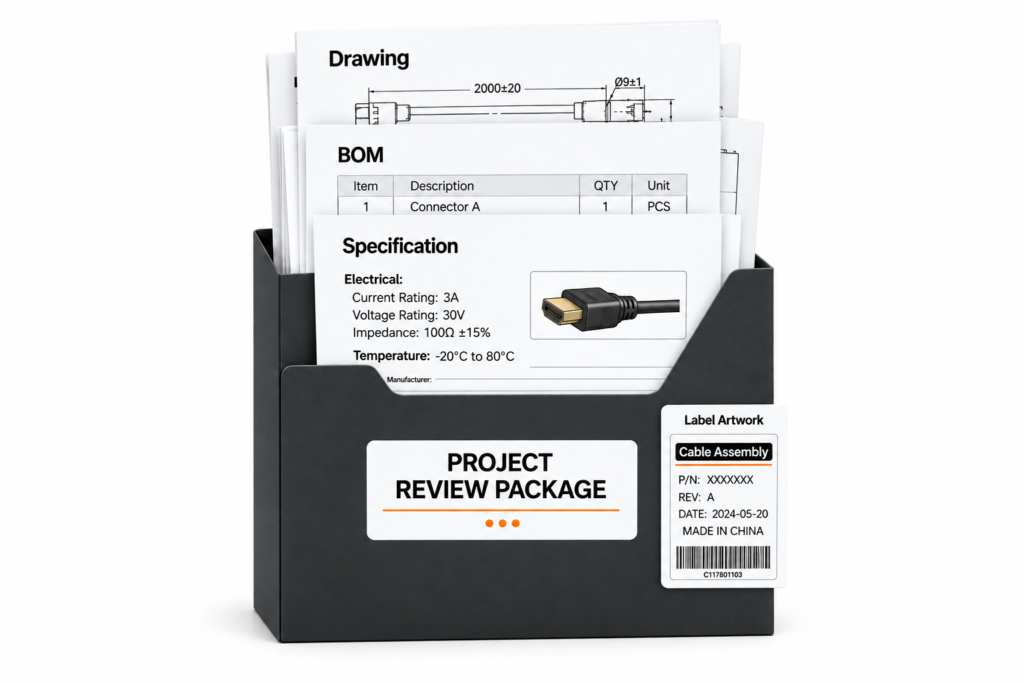
A strong MPO-to-LC breakout fiber cable quotation should therefore be judged by more than the unit price at the bottom of the page. Procurement teams should check whether every supplier has priced the same fiber type, fiber count, MPO interface, connector gender, LC grouping, channel map, dimensions, optical requirements, test scope, labeling and packaging. A lower quotation built around unstated assumptions can become the more expensive option if the finished assembly needs to be reworked, replaced or reordered.
Cablivo supports overseas custom cable and fiber-optic cable projects through requirement review, connector confirmation, sample development, production preparation, quality inspection, packaging, labeling and shipment coordination. The practical starting point for an MPO-to-LC breakout project is to send the information already available rather than waiting for a perfect specification. A drawing, BOM, existing sample, connector photos, mating-equipment details, fiber type, length, polarity information, target quantity, testing requirements and packaging plan can provide a strong basis for review.
If some fields are still uncertain, identify them clearly. They can be checked before quotation and sampling instead of becoming assumptions hidden inside the purchase specification. For a custom MPO-to-LC breakout fiber cable assembly, that early engineering review is one of the most effective ways to improve quotation accuracy, reduce sample-to-production mismatch and make future repeat orders easier to control.
Project Inquiry Information to Prepare
- MPO interface and male/female requirement
- Fiber count and fiber type
- LC quantity and simplex/duplex arrangement
- UPC or APC requirements
- Polarity or fiber mapping
- Overall cable length
- Breakout length
- Cable construction or jacket requirement
- Mating equipment or transceiver information
- Optical performance and testing requirements
- Sample and production quantities
- Labeling requirements
- Packaging requirements
- Drawings, BOM, sample photos or connector references
For a custom quotation, send the available project information to Cablivo for specification review before sample development and production discussion.



