 Skip to content


A microphone cable assembly can look simple from the outside: a length of cable, a connector at each end, perhaps a label, boot, or molded strain relief. In production, however, two assemblies with almost the same appearance can require different connector models, conductor constructions, shielding systems, cable diameters, jacket materials, pin assignments, assembly processes, inspection methods, and packaging. A request such as “3-meter XLR microphone cable, 1,000 pieces” can start an RFQ, but it normally leaves too many decisions open for a production-ready quotation.
For an accurate microphone cable assembly quote, provide the application, connected equipment, drawing or sample reference, connector models, pin count, gender, pinout, cable length, conductor size, shielding, jacket requirements, cable diameter, strain relief, testing criteria, target quantity, labeling, packaging, and shipping information. Any item that is not yet confirmed should be clearly identified before the quotation becomes the basis for sampling or production.
The real challenge is not getting a supplier to put a price on a spreadsheet. The challenge is knowing what assumptions are hidden behind that price. A connector that is slightly different, an undefined shield termination, a cable diameter that does not fit the selected boot, or an additional packaging requirement can all change the project after the first quotation. The stronger RFQ brings those questions forward while changes are still easy to review.
What Project Details Are Required?
Application and Connected Equipment
“Microphone cable” describes a broad product category rather than one universal construction. A cable repeatedly coiled on a live stage experiences different mechanical stress from an assembly permanently installed inside a conference system, recording rack, broadcast console, communication device, or other equipment. The RFQ should therefore explain what the cable connects, how frequently it moves, how it is routed, and whether the installation places unusual demands on flexibility, interference control, connector retention, or cable diameter.
Application information often clarifies specifications that cannot be understood from connector photographs alone. A portable cable may need frequent coiling and repeated bending near the connector, while an equipment-integrated cable may have strict routing space, minimum bend radius, or connector-clearance limitations. If the assembly runs near power supplies, lighting systems, motors, radio equipment, or other possible interference sources, that context can also affect how shielding and grounding are reviewed before sampling.
Providing the connected-device model, mating connector, equipment-port photograph, or installation photo is especially useful when the interface is unfamiliar or mechanically restricted. These references do not replace a controlled drawing, but they help an engineering team understand what the drawing is trying to accomplish. The goal is to define the environment first and then select the cable construction, rather than starting with a generic cable and hoping it will fit the application.
Drawing, Sample, or BOM
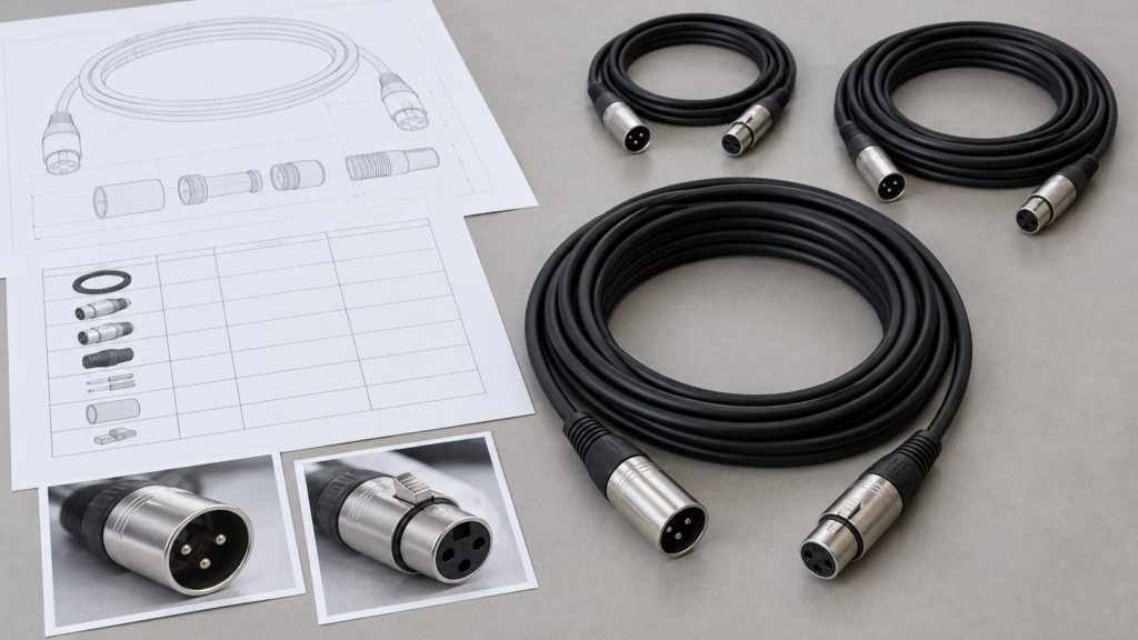
A controlled drawing is usually the strongest quotation reference because it can bring the cable length, connector A and connector B, pinout, tolerance, label location, heat-shrink position, molded geometry, cable-exit direction, and other dimensional requirements into one document. When a BOM is also available, it can identify the exact cable, connectors, terminals, sleeves, labels, or packaging materials that have already been approved by the customer’s engineering or procurement team.
Not every project begins with a finished drawing. Supplier-replacement projects may begin with an existing physical sample, while an early-stage project may have only connector photographs, sketches, equipment information, and a rough cable-length requirement. In those situations, detailed photographs of the complete assembly, connector faces, cable markings, labels, and packaging can support a preliminary engineering review and help identify what additional information is required before the quotation can be treated as final.
The important point is to separate confirmed information from open information. If the customer knows the connector and pinout but has not finalized the jacket material, that distinction should appear in the RFQ instead of being hidden. A manufacturer can then quote the confirmed configuration and clearly identify items that may affect price later. This makes quotations easier to compare and reduces disagreements when the project moves from initial pricing to sample development.
Project Stage and Quantity
A microphone cable project at concept stage needs a different type of support from a mature assembly being transferred from an existing supplier. Early projects may still require connector confirmation, cable-construction review, pinout verification, shielding discussion, and sample iteration. An approved production project may instead focus on matching the existing drawing, BOM, approved sample, labeling, packaging specification, and inspection criteria with as little deviation as possible.
Quantity also needs to be stated by SKU rather than only as a total annual estimate. A request for 5,000 identical three-meter assemblies is operationally different from 5,000 pieces divided across several lengths, connector configurations, or label versions. Multiple SKUs create additional material segregation, cutting programs, work instructions, packaging identification, and production changeovers even when the total number of finished assemblies is the same.
For many custom cable programs, an MOQ beginning around 500 pieces can be a useful starting reference, but the final requirement depends on connector sourcing, cable construction, material preparation, tooling, overmolding, packaging, and order mix. Providing a realistic first-order quantity together with an honest forecast gives procurement and manufacturing teams a more useful basis for evaluating cost than an inflated annual quantity that may not reflect actual releases.
Missing Information and RFQ Risk
The number of unresolved variables is one of the best indicators of how firm a quotation really is. A supplier can put a preliminary price on an incomplete specification, but procurement teams should understand that the price may change when connector models, cable construction, shielding, strain relief, testing, or packaging are finally confirmed. A professional quotation should make these open points visible instead of burying assumptions inside a unit price.
Consider a request reading, “Black 3-meter XLR microphone cable, 1,000 pieces.” The buyer has already provided useful information, but many variables may remain open: the connector manufacturer, exact connector model, pin count, conductor gauge, cable OD, jacket material, shield design, pinout, shield termination, strain relief, electrical test, label format, and individual packaging. Each of these decisions can affect materials, processing, testing, or assembly time.
The practical objective is therefore not to create the largest possible RFQ document. It is to close the variables that materially influence the finished assembly and clearly identify the rest. This approach allows engineering, purchasing, and production teams to work from the same assumptions and makes it much easier to understand why two supplier quotations may differ even when both appear to describe the same microphone cable.
| Project Item | Useful RFQ Information | Practical Decision Value | Risk if Undefined |
| Application | Stage, studio, broadcast, intercom, installed equipment | Sets mechanical and shielding priorities | Wrong construction may be selected |
| Connected equipment | Device model, mating port, connector photo | Confirms interface compatibility | Connector may not mate correctly |
| Drawing | Length, connectors, pinout, dimensions, labels | Creates controlled quotation reference | Supplier must make assumptions |
| Physical sample | Existing approved assembly | Useful for supplier replacement | Internal construction may remain unknown |
| BOM | Cable, connectors, terminals, sleeves, labels | Supports sourcing review | Cost may change after material confirmation |
| Project stage | Prototype, pilot, mass production, transfer | Defines engineering workload | Development work may be underestimated |
| Quantity | Sample, first order, forecast by SKU | Supports material and production planning | Unit pricing can be misleading |
| Open points | Clearly marked TBC items | Separates firm requirements from estimates | Preliminary pricing may be treated as final |
Which Connector Details Matter?

Connector Family, Gender, and Pin Count
Three-pin XLR is widely associated with balanced analog microphone connections, but a manufacturer should not assume that every microphone cable uses a standard three-pin male-to-female configuration. Professional audio, intercom, headset, broadcast, and equipment-specific applications can use different pin counts, miniature versions, right-angle arrangements, TRS connectors, or proprietary interfaces. Both ends therefore need to be identified individually in the RFQ.
A useful connector definition includes the family, gender, number of contacts, straight or right-angle form, cable or panel mating relationship, and any controlled manufacturer part number. If the assembly connects to an existing device, the mating interface should also be confirmed. A connector can have the right general appearance and still use a different insert, contact arrangement, shell geometry, cable clamp, or locking mechanism.
For conventional three-pin balanced analog microphone wiring, a common convention uses Pin 1 for shield or ground, Pin 2 for the positive signal, and Pin 3 for the negative signal. That convention is useful for understanding a typical application, but it should never replace the approved project drawing. Production should follow the customer-controlled pinout rather than relying on assumptions about what a microphone cable “normally” uses.
Exact Model and Mating Interface
Providing the connector manufacturer and exact part number makes the quotation significantly more reliable because it allows the sourcing and engineering teams to review availability, termination method, contact configuration, cable-entry range, strain-relief structure, and assembly process before the price is finalized. This is particularly important when an existing design has already passed product qualification or when appearance and mating feel are part of the customer’s approval criteria.
If the specified component is obsolete, difficult to source, or intentionally open to alternatives, that condition should be stated clearly. A professional quotation can then distinguish between the requested component and any proposed equivalent. The alternative should not silently replace the original part simply because both connectors share the same pin count or general shell shape.
For supplier-transfer projects, the mating device is another useful reference. A connector photograph taken from the front can identify the contact layout, but a side view, part number, or mating-port drawing often reveals additional mechanical information. Where installation space is restricted, the connector length, cable exit direction, latch position, and boot dimensions may matter just as much as the electrical contacts.
Pinout and Shield Termination
The pinout defines what the cable actually does electrically. A controlled wiring table should show the relationship between every contact on connector A and the corresponding contact on connector B, including signal conductors, shield or drain wires, unused pins, connector-shell connections, and any non-standard wiring. This becomes especially important when the assembly uses different connector families at each end.
Shield termination should also be treated as a deliberate design decision rather than something automatically determined by the cable. Depending on the equipment architecture, the braid or drain wire may terminate to a signal-ground contact, connector shell, one side only, both ends, or another defined point. The correct arrangement comes from the customer’s electrical design and grounding strategy, not from the supplier’s preference.
Wire colors can be included as useful production references, but they should support the pinout rather than replace it. A color sequence can change between cable constructions or material suppliers, while connector positions remain the functional definition. A pin-to-pin table is easier to program into electrical test equipment and gives quality inspectors an objective reference when verifying finished assemblies.
Cable Entry and Strain Relief
The connector and cable should be reviewed as one mechanical system. Every cable connector has a practical cable-entry and clamping range, and the selected cable OD must work with the boot, chuck, gland, or strain-relief structure. An electrically suitable cable that is too small can clamp poorly, while one that is too large may be difficult or impossible to assemble correctly.
This becomes particularly important for microphone cables that are frequently handled. Repeated bending tends to concentrate stress near the point where the flexible cable exits the rigid connector. A properly matched strain-relief design distributes this movement more gradually and helps protect conductor and shield terminations. The required solution can be a standard connector boot, a chuck-type clamp, heat-shrink reinforcement, or a custom molded structure depending on the project.
If custom overmolding is required, the RFQ should include the desired molded shape, cable-exit direction, critical dimensions, appearance requirements, and any mating-clearance restrictions. Tooling and sample validation may be necessary before mass production. Overmolding can support connector protection and strain relief, but it should be treated as a functional engineered feature rather than decorative plastic added after the cable has already been designed.
| Connector Parameter | Typical Project Choice | What Must Be Confirmed | Selection Value |
| Connector family | XLR, mini-XLR, TRS, proprietary | Exact mating interface | Prevents compatibility errors |
| Common analog XLR | 3-pin | Do not assume for every project | Typical balanced microphone use |
| Gender | Male / female | Define each end separately | Ensures correct equipment mating |
| Pin count | 3, 4, 5 or project-specific | Follow equipment specification | Prevents wrong insert selection |
| Pinout | Pin-to-pin mapping | Drawing controls production | Prevents wiring errors |
| Shield termination | Pin, shell, one end, both ends | Must be explicitly defined | Controls grounding arrangement |
| Cable OD | Often about 4–7 mm for many flexible professional cables | Verify against selected connector | Determines boot and clamp fit |
| Orientation | Straight or right-angle | Installation clearance | Prevents mechanical interference |
| Strain relief | Standard boot, chuck, custom mold | Match cable OD and movement | Protects cable entry |
| Connector model | Exact P/N or approved alternative | Confirm availability before sample | Reduces sourcing risk |
Which Cable Specifications Affect the Quote?

Cable length, conductor construction, AWG, core count, shielding, cable OD, jacket, flexibility, and controlled electrical characteristics can all influence a microphone cable quotation. Professional audio cables that look nearly identical from the outside may contain very different materials and internal structures, which is why finished length and connector type alone are not enough to define a repeatable production assembly.
Conductor Size and Construction
Flexible microphone cable commonly uses stranded copper conductors because repeated movement, coiling, and bending would make a solid conductor unsuitable for many portable audio applications. Professional microphone cable constructions can often be found in approximately the 22–26 AWG range, although that should be treated as a common industry reference rather than a universal requirement. The correct gauge depends on electrical needs, flexibility, overall cable diameter, connector compatibility, and the intended operating environment.
A larger conductor is not automatically a better solution. Increasing conductor size can increase material usage and cable diameter while reducing the space available for insulation, shielding, or filler inside a controlled OD. It may also change flexibility and connector compatibility. At the other extreme, selecting a very small conductor simply to obtain a thin cable may not match the mechanical or electrical expectations of the project.
Conductor material and stranding pattern can also matter. Bare copper and tinned copper are common possibilities, while strand count and individual strand diameter influence flexibility. Where an approved cable specification already exists, providing the manufacturer and cable part number is generally safer than asking a supplier to reproduce the product from appearance. For a new custom design, the RFQ can instead define the required AWG, conductor material, flexibility, and target OD so the construction can be reviewed as a whole.
Shielding Structure
Shielding is one of the most important variables in low-level audio and microphone cable construction, but the word “shielded” does not define how the shield is made. Common professional structures include braided copper shielding, served or spiral shields, foil shielding, and combinations of multiple layers. Each approach has different characteristics in flexibility, coverage, termination, manufacturing complexity, and mechanical durability.
Many professional braided audio cables use shield coverage in the approximate 85–95% range or higher, although the actual value must come from the selected cable specification. A higher percentage should not be treated as a universal guarantee of superior performance because connector termination, cable geometry, grounding, installation environment, and overall system design also influence interference behavior.
For a project with known interference concerns, the customer should identify the operating environment and any controlled shielding requirements rather than simply requesting “double shield” or “maximum shielding.” If the drawing specifies braid coverage, foil construction, drain wire, or termination method, those details should be part of the quotation. When the requirement is still open, engineering review can compare practical structures based on flexibility, diameter, processing, and the actual signal environment.
Cable OD, Flexibility, and Jacket
Many flexible professional microphone cables fall roughly within the 4–7 mm outer-diameter range, while miniature constructions can be smaller and heavy-duty cables can be larger. This range is useful as a reference point when discussing connector compatibility, but the final OD should come from the project requirements. A cable needs to fit the selected connector boot or chuck and may also need to pass through a panel opening, cable guide, equipment housing, or other mechanical restriction.
Flexibility is similarly application-specific. A stage cable that is coiled after every use, a boom cable that moves continuously, and a fixed studio installation do not need to feel or behave the same. Conductor stranding, internal fillers, shield design, jacket material, wall thickness, and OD all contribute to the finished cable’s flexibility. Asking for “very flexible cable” is useful as an initial preference, but a physical reference or specific operating condition communicates much more.
Jacket material affects more than appearance. PVC is widely used in general cable applications, while TPE, TPU, PUR, silicone, and other materials may be considered when a project requires a particular combination of flexibility, abrasion resistance, surface feel, temperature performance, chemical resistance, or environmental durability. No single material is automatically the premium choice for every microphone cable. Selection should follow the application, required certifications, manufacturing process, and target cost.
Length and Controlled Dimensions
Finished cable length should be defined together with the measurement method. A specification of “3 meters” can mean cable-jacket length, connector-face-to-connector-face length, or another controlled reference depending on the customer’s drawing system. For portable stage cables, a small difference may be relatively unimportant, while equipment-integrated assemblies can require tighter dimensional control because the cable must route between fixed locations.
Tolerance should therefore reflect actual functional need instead of being made unnecessarily tight. Cutting and assembly processes can control length consistently, but every tighter tolerance becomes a production requirement that needs to be measured and maintained. If the product uses a custom molded connector, the finished overall length may also depend on where the molded body begins relative to the cable jacket.
Multiple cable lengths should appear as separate SKUs with quantities for each configuration. A program containing 1-meter, 2-meter, 3-meter, 5-meter, and 10-meter versions may share connectors and cable construction but still require different cutting programs, labels, packaging, material planning, and inventory control. This detail becomes especially important when procurement teams compare quotations for a mixed-SKU annual program.
| Cable Specification | Common Industry Reference or Option | What to Confirm | RFQ Impact |
| Conductor gauge | About 22–26 AWG is common in many flexible microphone designs | Drawing or approved cable specification | Material, OD, flexibility |
| Conductor type | Stranded copper commonly used | Bare/tinned copper and strand construction | Flexibility and sourcing |
| Core count | 2 conductors common for balanced analog; 4 used in some star-quad designs | Application and wiring | Construction and material cost |
| Shield | Braid, served/spiral, foil, combined structure | Coverage and termination | Interference control and processing |
| Braid coverage | Roughly 85–95%+ occurs in many professional designs | Verify selected cable specification | Material and shield construction |
| Cable OD | Roughly 4–7 mm common in many flexible professional designs | Connector and routing requirements | Connector fit and handling |
| Jacket | PVC, TPE, TPU, PUR, silicone or project-specific | Environment and use condition | Flexibility, durability, cost |
| Length | Project-specific | Reference points and tolerance | Material use and installation fit |
| Color | Black common, custom colors possible | Approved color reference | Material preparation |
| Capacitance | Varies considerably by cable construction | Use approved specification or project limit | Relevant to signal behavior over length |
What Performance and Testing Are Required?

Electrical and Wiring Verification
The most basic requirement for a finished cable assembly is that every electrical connection agrees with the approved wiring drawing. For a conventional straight-through three-pin XLR assembly, an electrical tester may verify 1-to-1, 2-to-2, and 3-to-3 continuity while also checking for unintended shorts or opens. Proprietary, hybrid, or equipment-specific assemblies should instead be programmed according to their controlled pinout.
A practical production test can include correct pin-to-pin continuity, absence of open circuits, absence of unintended cross-connections, shield connection according to the drawing, and any customer-defined functional verification. Where the assembly contains several conductors or unusual shield termination, automated electrical testing becomes particularly useful because it provides a consistent method for comparing every finished unit against the approved connection map.
The phrase “100% test” should still be defined carefully. It is more useful to state that every finished assembly will undergo specified continuity and wiring checks than to use a broad claim that could mean different things to the factory and the customer. Quality criteria should identify what is tested, how it is tested, and which drawing or test program defines acceptance.
Signal and Shielding Considerations
Microphone cables commonly carry low-level signals, which makes conductor construction, cable capacitance, shielding, grounding, and connector termination relevant to performance. However, not every project requires specialized laboratory-level signal measurements. Many standard professional applications can be controlled effectively through an approved cable specification, correct pinout, consistent shield termination, reliable soldering, and defined electrical inspection.
If capacitance is an important design criterion, the requirement should be stated explicitly. Cable capacitance is normally specified per unit length, which means total capacitance increases as the finished cable becomes longer. For example, if a particular cable construction is rated at 50 pF/m conductor-to-conductor, a 10-meter length would contribute approximately 500 pF before accounting for connector and measurement conditions.
This example is not a recommended microphone cable specification; it simply illustrates why length and cable construction should be reviewed together. When a customer has an approved maximum capacitance, resistance, impedance, or other electrical value, that requirement belongs in the RFQ. Where no such limit exists, the manufacturer should not invent one merely to make the quotation appear more technical.
Mechanical Reliability
Mechanical testing becomes useful when it reproduces the stresses the cable will experience in actual use. A stage microphone lead that is repeatedly coiled, pulled, stepped on, and bent near the connector may justify a defined bending or swing test, while an installed cable that rarely moves may place greater emphasis on connector retention and assembly workmanship.
Possible verification methods include connector pull-force testing, termination tensile testing, repeated-bending or swing testing, and connector insertion or withdrawal testing. There is no universal force or cycle count that applies to every microphone cable assembly. The correct requirement should come from the customer’s qualification plan, equipment design, connector specification, or internal acceptance criteria.
When the requirement is already defined, the RFQ should state the test conditions clearly: force, direction, duration, bend angle, bend radius, attached load, cycle count, or connector mating cycles. A request for “durability testing” without any acceptance criteria leaves too much room for interpretation. During early development, samples can also be used to evaluate mechanical behavior before the final reliability plan is frozen.
Environmental and Compliance Requirements
Many microphone cables operate in ordinary indoor environments and do not require severe environmental validation. Other assemblies may be used in outdoor events, industrial communication systems, transportation equipment, broadcast vehicles, medical devices, or other applications where temperature, humidity, corrosion, jacket behavior, or material compliance has greater importance.
The application should therefore be defined before environmental tests are selected. Temperature-and-humidity testing may be relevant for changing environmental conditions, while salt-spray testing can be useful for exposed metal parts in corrosion-sensitive applications. Insulation or dielectric testing may be appropriate for certain circuits, but it should not automatically be added to a low-voltage audio cable simply because the factory owns the equipment.
Compliance needs the same discipline. CE, RoHS, REACH, UL, medical, aerospace, flame-retardant, or other requirements should only be stated when the actual product scope, target market, materials, documentation, and evidence support them. For a quotation, it is more professional to identify the target market and applicable requirement first and then confirm the necessary materials or testing than to assume every microphone cable needs every available certification.
| Test or Performance Item | Practical Acceptance Basis | When It Is Useful | Key RFQ Detail |
| Pinout test | Match approved wiring table | Nearly all custom assemblies | Connector-to-connector mapping |
| Continuity | No unintended open circuit | Nearly all wired assemblies | Test controlled circuits |
| Short-circuit check | No unintended cross-connection | Multi-conductor assemblies | Define shield relationship |
| Shield connection | Match drawing | Signal-sensitive applications | Pin, shell, one end or both |
| Capacitance | Approved cable spec or customer limit | Long or electrically controlled cables | pF/m or full-length limit |
| Pull force | Customer or connector requirement | Portable/high-stress assemblies | Force, direction and duration |
| Bend/swing | Defined cycles and geometry | Frequently flexed cables | Angle, radius, load, cycle count |
| Connector life | Defined mating cycles | Frequently connected equipment | Connector model and cycle target |
| Temperature/humidity | Project qualification plan | Outdoor or special environments | Temperature, humidity and duration |
| Salt spray | Component or customer requirement | Corrosion-sensitive applications | Duration and acceptance criteria |
| Hi-pot/insulation | Project electrical-safety requirement | Applicable special circuits | Voltage, time and leakage limit |
| Visual inspection | Drawing and approved sample | All finished assemblies | Color, molding, labels and workmanship |
How Do Order Details Affect the Quote?
Commercial details can change a microphone cable quotation even when the electrical construction remains identical. Quantity, SKU mix, sampling, tooling, cable printing, labels, individual packaging, carton requirements, shipping destination, and project documentation all influence material preparation and production planning. These requirements should be included early instead of being introduced after a basic cable price has already been approved.

Quantity, MOQ, and SKU Mix
Unit price cannot be evaluated meaningfully without quantity. Cable materials may be purchased by reel or production lot, connectors can have supplier MOQ requirements, and custom jackets, molded structures, labels, or packaging can introduce their own setup conditions. A quotation for 500 pieces and a quotation for 20,000 pieces should not be expected to use exactly the same cost structure.
For many custom cable projects, a starting MOQ around 500 pieces may be possible, although the final requirement depends on connector availability, cable construction, materials, overmolding, tooling, packaging, and the total production mix. Procurement teams should therefore provide the realistic first order and, when available, a reasonable future forecast rather than focusing only on a theoretical high-volume price.
SKU mix often has a greater operational impact than customers initially expect. Five thousand identical assemblies require one set of cutting instructions, labels, and packaging references. The same 5,000 pieces split among ten cable lengths and several connector combinations create additional work instructions, material segregation, changeovers, inspection references, packaging identification, and inventory control. Quantity should therefore be provided by exact SKU whenever several variants share the same program.
Sampling and Production Approval
Sampling is often the most practical bridge between a quotation and mass production. A physical sample allows both sides to verify connector mating, finished cable length, pinout, flexibility, OD, strain relief, visual appearance, label position, and packaging fit before the approved design is repeated across a production order.
Sampling becomes particularly important when the project uses a new cable construction, unusual connector combination, custom molded strain relief, special jacket requirement, or supplier-replacement reference that has not yet been converted into a complete engineering drawing. The sample helps expose differences that may not have been obvious during preliminary quotation, and the resulting feedback can be incorporated into a revised sample or controlled specification.
Sample timing should not be promised before the project has been reviewed. Connector sourcing, cable material preparation, tooling, overmolding, and testing can all influence development time. Once the sample is approved, the final drawing, BOM, material specification, label artwork, packaging file, and test criteria should be aligned with the approved version so that production is not forced to rely only on a physical reference.
Labels, Branding, and Packaging
Packaging does not change the electrical behavior of a microphone cable, but it can materially change production work and quotation cost. A simple bulk cable may only require controlled coiling and carton packing, while a retail program can require individual bags or boxes, hook-and-loop ties, printed sleeves, barcode labels, customer part numbers, country-specific artwork, inner cartons, and detailed master-carton marks.
Labels can also carry production-critical information rather than only branding. SKU, cable length, barcode, customer code, lot information, or orientation can be used to distinguish assemblies that look almost identical. In a multi-SKU program, accurate labeling becomes part of quality control because a correctly manufactured cable can still cause a customer problem if it is packed under the wrong part number.
Artwork should therefore be controlled before mass production. Logo files, printing positions, label dimensions, variable barcode data, carton marks, and packaging instructions should be reviewed as part of the project rather than delivered after finished cables are already waiting to ship. This becomes especially important for overseas brand programs where the product may move directly from factory packaging into a regional warehouse or retail channel.
Shipping and Final RFQ Package
The shipping destination helps define the commercial scope of the quotation. An ex-factory price, FOB price, and delivered price represent different responsibilities, and destination information can influence export-carton design, shipping marks, logistics documentation, and freight discussions. When customers use their own forwarder, those instructions can be stated separately from the product specification so the manufacturing price remains easy to understand.
A mature RFQ usually combines the technical and commercial information into one controlled project package instead of distributing critical details across a long chain of emails. The package can include the current drawing, BOM, connector part numbers, cable specification, pinout, reference photographs, quantity by SKU, testing requirements, label files, packaging specification, target market, and destination.
When project files contain proprietary product information, drawings, branding, or supplier-transfer details, confidentiality requirements or an NDA can be discussed before sensitive information is shared. The purpose is not to make the process bureaucratic. It is to give engineering, purchasing, production, quality, packaging, and logistics teams a common reference so that the product being quoted is the same product that will eventually be sampled and manufactured.
| Commercial Item | Example or Decision Point | Effect on Quotation | What to Submit |
| MOQ | Around 500 pcs may be possible for many custom projects | Depends on materials, connectors and setup | Realistic first order |
| Quantity | 500 / 1,000 / 5,000+ pieces | Affects sourcing and production planning | Quantity by SKU |
| SKU mix | One configuration vs multiple lengths/connectors | More changeovers and inventory control | SKU breakdown |
| Sample | New design or supplier replacement | Adds engineering and material preparation | Drawing, sample or BOM |
| Tooling | Standard connector vs custom molded structure | May create tooling cost | Drawing or reference sample |
| Cable printing | None, logo, P/N, meter marking | Adds setup and artwork control | Artwork and print position |
| Labeling | SKU, barcode, batch, customer code | Adds material and inspection | Approved label file |
| Packaging | Bulk coil, bag, retail pack, custom packaging | Changes labor and packaging material | Packaging specification |
| Carton marking | Generic or customer-specific | Affects export preparation | Carton instruction |
| Destination | Country, port, warehouse | Defines logistics scope | Shipping location |
| Documentation | Standard or project-specific files | Adds coordination requirements | Required document list |
| Confidentiality | Normal project or NDA discussion | Controls information-sharing process | Confidentiality requirement |
An accurate microphone cable assembly quotation ultimately comes from specification clarity rather than from the speed of the first reply. The objective is not to force every project into a large engineering package, but to identify the details that genuinely control connectors, cable construction, wiring, shielding, mechanical design, testing, production, and commercial scope. When those variables are clear, quotations become easier to compare and sample approval becomes much more meaningful.
Cablivo supports custom cable, wire harness, and cable assembly projects from requirement review, drawing and BOM review, connector confirmation, material discussion, and sample development through production preparation, quality inspection, labeling, packaging, and shipment coordination. The manufacturing base behind the Cablivo brand has 18 years of industry experience, more than 20,000 square meters of factory space, a team of more than 1,500 people, and three manufacturing bases supporting project-based cable production for overseas markets.
If you are preparing a custom microphone cable assembly project, send the available drawing, BOM, sample photos, connector models, pinout, cable length, AWG, shielding requirements, target quantity, test requirements, label files, and packaging plan. If some specifications have not been finalized, mark them clearly as open points. The project can then be reviewed around what is already confirmed, what still requires engineering discussion, and what must be validated through sampling before mass production.



