 Skip to content


An M8 male cable assembly may appear to be a simple combination of a compact circular connector and a length of cable, but the quotation process is rarely that simple. Two assemblies can look almost identical from the outside while using different coding, contact counts, pin assignments, conductor sizes, jacket materials, shielding structures and opposite-end terminations. These hidden differences affect connector sourcing, tooling, processing time, testing, packaging and long-term production consistency.
An accurate M8 male cable assembly quote requires the connector coding, pin count, orientation, mating interface, pinout, cable length, conductor size, jacket material, shielding, electrical load, application environment, testing requirements, order quantity and packaging plan. A controlled drawing or BOM is preferred, but clear connector photographs, an existing sample and detailed application information can also support an initial engineering review.
A quotation based on incomplete information may look attractive at first, but it often describes a different product from the one the customer actually needs. A supplier may assume a straight connector when the installation requires a right-angle exit, or quote an unshielded PVC cable when the final application requires a shielded PUR construction. The price changes later because the specification changes, not simply because the supplier changes its mind. A clearer RFQ reduces those surprises before the first sample is made.
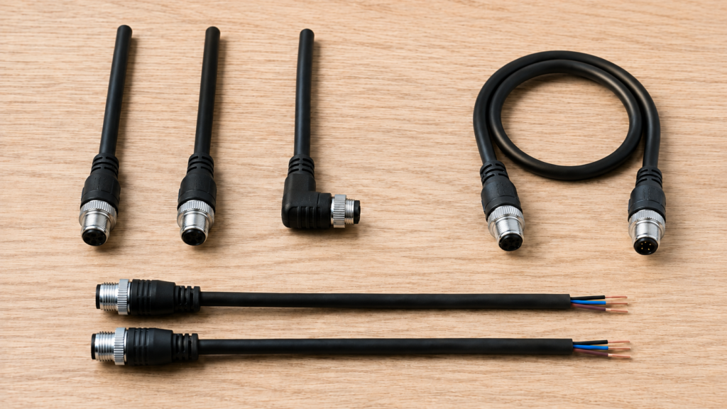
Why Is “M8 Male Cable Assembly” Not Enough?
“M8 male cable assembly” identifies only the general connector family and the plug side of the interface. It does not define coding, contact count, orientation, wiring, cable construction, opposite termination, electrical function or application conditions. Until those details are confirmed, a supplier can provide only an assumption-based estimate rather than a dependable production quotation.
What the Name Confirms
The term “M8” tells the manufacturer that the project involves a compact circular connector from the M8 family. The term “male” normally describes the plug side with male contacts that mates with a corresponding female receptacle. This information narrows the component category, but it does not create a production-ready specification.
The outer threaded interface can remain similar while the internal contact arrangement changes. M8 product families may include three, four, five, six or eight positions, depending on the coding and intended application. The housing may be straight or angled, the assembly may be shielded or unshielded, and the cable may end as a pigtail or continue to another connector.
The product name also says nothing about the installation. A connector selected for an open machine frame may not fit inside a recessed equipment port. A straight plug may require more installation depth than the available space allows, while a right-angle plug may point in the wrong direction after tightening. The name begins the conversation, but it does not finish the engineering definition.
What Remains Open
The connector insert is the first major unknown. The manufacturer still needs to know the required coding, populated positions, pin numbering and keying direction. A photograph taken from the side may show the housing but hide the information that determines whether the connector can mate with the equipment.
The cable remains equally undefined. The request does not state conductor count, AWG, outer diameter, insulation, jacket material, shielding, flexibility or cable color. It also does not explain whether the cable carries sensor power, switching signals, actuator control, communication data or another electrical function.
The opposite end may involve more uncertainty than the M8 end. It could be supplied as cut conductors, stripped wires, tinned wires, ferrules, terminals, an M12 connector, a PCB connector or a customer-specific component. Each option changes the material list, tooling, assembly work and inspection method.
An apparently small detail such as strip length can also matter. A pigtail prepared for a terminal block may require different conductor exposure and labeling from a cable intended for direct soldering inside a device.
How Assumptions Change Cost
A supplier preparing a quick estimate may assume a common M8 configuration, a standard straight molded body, four conductors, general PVC cable, an open-wire end and basic continuity testing. That can produce a price quickly, but it may not represent the required assembly.
A shielded cable normally costs more than an unshielded construction because the cable structure and shield termination require additional materials and processing. A right-angle connector may use a different component or mold. A custom overmold can introduce tooling, engineering review and sample adjustment. Individual wire labels, barcode bags and protected export packaging also create work that is not included in a basic bulk-packed cable.
The same issue affects lead time. A widely available connector may be sourced quickly, while a less common code, contact count or approved brand may require a longer purchasing cycle. If the quotation does not identify the assumed connector source, two prices may appear comparable even though they are based on different availability and quality conditions.
A useful quotation clearly separates confirmed specifications from temporary assumptions. This gives the customer an opportunity to correct the technical basis before approving a sample or comparing several suppliers.
How Incomplete RFQs Create Risk
The most expensive mistake is not always an incorrect unit price. It may be a sample that fits visually but cannot connect, or a production batch that cannot be installed in the customer’s equipment.
A mirrored pinout can send voltage or signals to the wrong circuit. An incorrect keyway can prevent mating. An oversized overmold can interfere with a recessed socket. A cable chosen for fixed routing may fail early when it is repeatedly bent near the connector. These risks are difficult to detect when the quotation focuses only on length and quantity.
Incomplete specifications also make supplier comparison unreliable. One quotation may include a shielded PUR cable, wire-number labels and pull-force testing, while another may describe an unshielded PVC cable with continuity testing only. The lower price is not necessarily more competitive because it may represent a simpler assembly.
Connector confirmation is therefore treated as a central part of custom cable development. The model, gender, pin count, mating part, interface direction, waterproof expectation, shielding and overmolding requirement should be reviewed before sampling.
| Missing detail | Common assumption | What may change later | Main project risk |
| Connector coding | A common code is selected | Insert and sourcing | Cable cannot mate |
| Contact count | Three or four positions are assumed | Connector and cable cores | Required circuit is missing |
| Orientation | Straight plug is assumed | Housing and mold | Cable cannot fit |
| Cable exit | Any right-angle direction is accepted | Mold orientation | Cable points toward an obstacle |
| End-B | Cut pigtail is assumed | Connector, terminal and labor | Assembly arrives incomplete |
| Cable jacket | General PVC is assumed | Material and flexibility | Cable is unsuitable for use |
| Shielding | Unshielded structure is assumed | Cable and termination work | Interference risk |
| Pinout | Standard colors are assumed | Wiring and testing | Electrical mismatch |
| Overmold | Existing mold is assumed | Tooling and sampling | Size or strain relief is unsuitable |
| Packaging | Bulk packing is assumed | Labels, bags and protection | SKU or handling errors |

Which M8 Connector Details Are Required?
A quote-ready M8 connector specification should identify coding, pin count, gender, orientation, mating interface, opposite-end termination, shielding, sealing and overmolding. A manufacturer part number or controlled drawing is the most reliable reference, while clear connector-face photographs can support identification when complete technical documentation is not available.
Coding and Pin Count
Connector coding controls the physical keying of the interface and helps prevent incompatible plugs and receptacles from mating. It should be taken from the equipment drawing, receptacle datasheet, existing approved cable or connector part number rather than selected from appearance alone.
Pin count must also be confirmed before cable construction is discussed. Different contact counts require different inserts, conductor numbers, wire mappings and inspection fixtures. A four-position assembly should not be quoted from a photograph that does not clearly show whether all four contacts are present or whether one position is unused.
When the exact connector number is unknown, provide a sharp image taken directly toward the mating face. The keyway, contact positions and coupling structure should be visible. A second image should show the equipment-side receptacle, while a wider image should show the surrounding installation space.
The pin-numbering direction must be stated in the wiring document. A connector viewed from the mating side can appear mirrored when compared with the cable-entry side. The note “viewed from mating face” removes a common source of pinout errors.
Orientation and Clearance
A straight connector is normally suitable when there is enough space behind the equipment port for the connector body, cable bend and installation tool. A right-angle connector can reduce depth, but the exit direction must be coordinated with the machine layout.
The phrase “90-degree connector” does not fully define orientation. The cable may need to exit upward, downward, left or right relative to the keyway after the coupling nut is tightened. A marked installation photograph can communicate this more clearly than a general written description.
Clearance should be checked around the receptacle, not only behind it. The molded body, coupling nut and strain relief may interfere with an enclosure wall or nearby connector even when the threaded interface itself is compatible. Recessed sockets need particular attention because an oversized molded body may not reach the mating interface.
The installation method also matters. A connector that can be tightened by hand on an open workbench may be difficult to assemble inside a compact machine. Providing available space and access information allows the connector structure to be reviewed before the first sample is made.
Mating Interface and End-B
The mating interface should be treated as part of the cable specification. A connector may have the expected contact count but still fail to mate because the coding, keyway or mechanical depth is different.
Useful evidence includes the equipment-side receptacle part number, technical drawing, equipment model and close front-facing photograph. When possible, an existing mating component or approved sample can be supplied during prototype development to support fit confirmation.
The opposite end requires the same level of detail. For a pigtail, the customer should define whether conductors are cut, stripped, tinned, fitted with ferrules, crimped with terminals or identified with individual labels. Strip length, exposed conductor length and terminal part numbers should be included.
For a double-ended cable, the second connector needs its own manufacturer, model, gender, orientation and pin mapping. It should not be described simply as “another connector,” because End-B materials and processing can represent a significant part of the assembly cost.
Overmolding and Sealing
Overmolding protects the cable-to-connector transition, supports strain relief and creates a repeatable molded shape. It can also control the cable-exit direction, body dimensions, surface finish, color and logo position.
An existing mold may be suitable when the customer accepts a standard shape. A custom mold may be required when the cable must fit a restricted space, match a branded appearance or provide a specific strain-relief profile. Tooling requirements should be identified before quoting because they affect sample cost, development time and long-term production planning.
Sealing should be defined by the actual application. Occasional splash exposure, regular washdown and temporary immersion are different conditions. The customer should identify how the cable is used, whether the connector is tested in a mated condition and which acceptance standard is required.
A molded connector should not automatically be described as meeting a particular IP rating. Sealing depends on the connector system, mating condition, material, structure and agreed test method. Industrial M8 projects may involve shielding, overmolding, strain relief, pull-force evaluation and bending tests according to the application.
| Connector item | Information to provide | Judgment standard | Quotation value |
| Coding | Code from drawing or receptacle data | Must match the mating keyway | Prevents incompatible selection |
| Pin count | Exact populated positions | Must support every circuit | Defines connector and cable cores |
| Gender | Plug and receptacle details | Confirm by contact structure | Avoids description errors |
| Face view | Clear image with viewing direction | Keyway and contacts visible | Supports identification |
| Orientation | Straight or right-angle | Must fit installation space | Defines housing and mold |
| Angled exit | Direction relative to equipment | No interference after tightening | Prevents unusable samples |
| Mating part | Model, drawing or sample | Mechanical fit confirmed | Reduces connection risk |
| End-B | Connector, terminal or pigtail | All processing steps defined | Completes the BOM |
| Overmold | Standard or custom | Dimensions and tooling reviewed | Clarifies development cost |
| Sealing | Exposure and test requirement | Complete mated system evaluated | Defines validation scope |

What Cable Specifications Are Needed?
A complete cable specification should define finished length, tolerance, conductor count, wire gauge, conductor material, jacket, outer diameter, shielding, pinout, color and movement requirement. The M8 connector size cannot determine these values by itself because the required cable construction depends on electrical load, signal type, routing space, environmental exposure and expected movement.
Length and Tolerance
Finished cable length must be connected to a clear measurement reference. One drawing may measure from the connector mating face to the cut wire end, while another may measure only the exposed cable between molded bodies. Both can be described as one meter, but the finished products will not be the same.
The drawing should identify the start and end points, nominal length and allowed tolerance. Pigtails also need jacket strip length, conductor length and exposed copper or terminal dimensions. Multi-branch cables require dimensions for each branch and breakout position.
Tolerance should reflect how the cable is installed. A short internal assembly routed between two fixed components may need tighter control than a long field cable with extra routing length. An unnecessarily narrow tolerance can increase cutting, inspection and scrap costs without improving installation.
Length can also influence electrical performance. As the conductor becomes longer, resistance and voltage drop increase. A wire gauge that works for a short sensor lead may need to be reconsidered for a much longer run, depending on the current and allowable voltage loss.
Conductors and Electrical Load
Wire gauge influences current capacity, resistance, voltage drop, cable diameter, flexibility, connector compatibility and cost. The RFQ should state AWG or square-millimeter size, conductor count, conductor material and stranding where these values are already defined.
Compact M8 assemblies frequently use relatively small conductors because the connector and cable entry are limited in size. Wire sizes around 22 to 26 AWG can be encountered in commercial configurations, but this range should be treated only as a reference. The final conductor must be matched to the load, cable length, terminal capacity and available outer diameter.
Normal operating voltage and current should be provided together with any peak load. A sensor circuit may have a low continuous current but a different transient condition. A longer cable may need a larger conductor even if the connector remains unchanged.
Signal function also matters. A cable carrying simple on/off signals may not require the same internal arrangement as one used for communication or signal-sensitive equipment. Explaining what the cable does allows the manufacturer to identify whether conductor arrangement or shielding needs additional review.
Pinout and Identification
A pinout should map every M8 contact to a conductor color, End-B terminal or second connector contact. It should identify power, ground, signal, shield and unused positions.
Color conventions can support assembly, but they should not replace an explicit wiring map. A standard brown, blue, black or white sequence may be familiar in some sensor applications, yet a custom cable may follow a customer-specific design. Production and testing must use the approved drawing rather than general expectations.
The viewing direction should appear beside the connector diagram. A note such as “M8 male viewed from mating face” prevents the pin layout from being interpreted in reverse.
Wire identification becomes particularly valuable on open-ended cables. Individual wire-number labels can reduce installation mistakes in control cabinets and equipment assembly. Label text, size, location and material should be confirmed before production, especially when several similar cable variants are packed together.
Continuity, pinout and wire-sequence checks can then be performed according to the approved specification and project requirements.
Jacket and Shielding
Jacket selection begins with the real application. PVC is commonly used for general fixed installations, while PUR may be considered when abrasion, movement or industrial exposure is more demanding. Other materials may be discussed when the project has particular flexibility, temperature, chemical or regulatory requirements.
The customer should define any maximum outer diameter imposed by a cable gland, routing channel, receptacle or molded connector. M8 cable assemblies commonly use compact cable diameters, often within an approximate four-to-six-millimeter range, but the final size depends on conductor count, wire gauge, shielding and jacket structure.
Shielding must be described by construction and termination. Options may include foil shielding, braided shielding or a combined structure. The RFQ should state whether a drain wire is required and where the shield connects. A shield left unconnected is electrically different from one bonded to a metallic connector or grounding terminal.
Cable color, surface finish and print requirements should also be included when they affect installation, branding or SKU identification. These details are easier to control when they are included in the drawing and BOM before sampling.
| Cable parameter | Required project input | Useful judgment reference | Main impact |
| Finished length | Defined measurement points | Short jumper or multi-meter field run | Material, resistance and routing |
| Tolerance | Application-based limit | Avoid tighter tolerance without need | Cutting and inspection cost |
| Conductor count | Number of active circuits | Must match populated contacts | Cable structure |
| Wire gauge | AWG or mm² | Often around 22–26 AWG in compact examples | Current, voltage drop and OD |
| Cable diameter | Maximum or target OD | Often approximately 4–6 mm | Routing and mold fit |
| Electrical load | Voltage, current and peak load | Review together with length | Conductor selection |
| Pinout | Pin-to-wire and End-B map | Viewing direction required | Wiring accuracy |
| Jacket | PVC, PUR or defined option | Select by environment and motion | Flexibility and durability |
| Shielding | Foil, braid or combined | Termination method required | Signal and grounding |
| Identification | Color, printing or labels | Match SKU and installation needs | Assembly and traceability |

How Do Application Requirements Affect the Quote?
Application requirements determine whether the cable is suitable for its job rather than merely manufacturable. Installation space, movement, temperature, moisture, oil, vibration, electrical noise and expected service conditions can change the connector orientation, cable material, shielding, strain relief, overmold, testing and documentation included in the quotation.
Installation and Equipment
A useful application description identifies the equipment and the cable’s role. “Used on a machine” leaves too much uncertainty. “Connects a proximity sensor to an I/O module inside a packaging system” gives the engineering team a clearer understanding of electrical function, installation and service conditions.
Photographs of the installation area can reveal details that are difficult to describe. They may show a recessed receptacle, limited depth, nearby components, routing channels or restricted access for tightening the connector.
The customer should also explain how the cable will be installed and replaced. A cable mounted permanently inside an enclosure has different handling requirements from an exposed sensor cable that technicians disconnect regularly. The number of expected connection cycles may influence connector and strain-relief evaluation.
When several similar assemblies are installed on the same machine, identification becomes important. Cable color, wire-number labels, connector markings or product labels may help technicians distinguish functions and reduce installation errors. These requirements should be included during quotation because they affect production and packaging.
Static or Moving Use
A cable can feel flexible without being designed for continuous movement. The RFQ should distinguish fixed routing, occasional maintenance movement, repeated bending, drag-chain use and robotic motion.
For moving applications, provide the bend radius, movement distance, speed and bending location where known. A cable that repeatedly bends directly behind the connector places more stress on the overmold and conductor transition than one that moves gradually along its full length.
Cable support should also be described. A hanging cable can experience tensile load, vibration and bending at the same time. A correctly positioned clamp may reduce connector stress, while an unsuitable clamp position can concentrate movement at one point.
A bending requirement should include more than a requested cycle count. Test radius, load, speed, travel direction and failure criteria determine what the result actually means. Testing items therefore need to be confirmed according to the product and application rather than applied identically to every assembly.
Environmental Exposure
Temperature, water, dust, oil, coolant, chemicals, UV exposure, vibration and mechanical impact should be described separately. General terms such as “industrial grade” or “outdoor cable” do not provide enough information for reliable material selection.
Liquid exposure should be explained in practical terms. Occasional splash, daily washdown and temporary immersion create different sealing and jacket requirements. For oil or chemicals, the actual fluid and contact pattern should be identified when possible.
Both operating and storage temperatures may matter. A cable can operate in a moderate factory environment but experience colder or hotter conditions during transportation and storage. Published temperature ranges belong to specific cable and connector constructions, so they should not be copied from another M8 product without reviewing the selected materials.
Vibration and mechanical impact may also influence cable routing and strain relief. If the cable is mounted close to a moving motor, pump or actuator, the manufacturer may need to consider connector support, clamp position and movement at the cable exit.
Testing and Documentation
Testing should address the failure risks that matter in the application. Common electrical checks may include continuity, wire sequence, pinout, polarity, insulation and connector fit. Mechanical checks may include pull force, bending or visual inspection of the molded transition.
The RFQ should define the test method, acceptance limit and reporting requirement whenever those details are important. “Pull test required” is incomplete without a force, direction and duration. “Waterproof test required” should identify the exposure, duration and whether the connector is tested while mated.
Documentation can also affect cost and preparation time. Some projects require only routine production inspection records. Others may need lot traceability, material declarations, first-article records, customer-specific reports or photographs of labels and packaging.
Certification and testing requirements should be confirmed according to the product type, target market and technical specification. A responsible manufacturer should not state that every assembly automatically carries every approval or receives every available test.
| Application condition | Information to provide | Possible design response | Quotation impact |
| Fixed installation | Routing and clamp locations | General or flexible cable | Standard electrical inspection |
| Repeated bending | Radius, speed and bend location | Flexible conductor and strain relief | Bending test discussion |
| Drag-chain use | Travel and chain space | Dynamic cable structure | Extended sample evaluation |
| Tight clearance | Receptacle depth and obstacles | Straight or angled connector | Fit and dimension review |
| Water exposure | Splash, washdown or immersion | Sealing and jacket review | Defined water-related test |
| Oil or coolant | Fluid type and contact frequency | Material selection | Compatibility discussion |
| Temperature | Operating and storage range | Jacket and mold material review | Environmental validation |
| Electrical noise | Nearby motors or drives | Shielding and grounding | Shield and continuity checks |
| Vibration | Source and cable support | Strain relief and clamp planning | Mechanical inspection |
| Traceability | Lot, serial or SKU requirement | Label and record design | Additional documentation |

How Do You Submit a Complete M8 Cable RFQ?
A complete M8 RFQ combines the technical specification, application conditions and commercial plan in one controlled package. A drawing and BOM are preferred, but a supplier can begin with connector photographs, an existing sample, equipment information and a clear requirement list. The final quotation should identify confirmed specifications, unresolved points, quantity basis, testing and packaging.
Drawing, BOM and Revision
The strongest RFQ package includes a dimensional drawing, pinout and BOM. Each document should have a revision number or issue date so both parties know which version has been quoted and approved.
The drawing should show connector orientation, cable length, tolerance, End-B termination, stripped-wire dimensions, label locations and overmold dimensions where relevant. The pinout should map every contact and state the viewing direction.
The BOM should identify connectors, cable, terminals, heat-shrink tubing, sleeves, labels and packaging components. It should also state whether approved alternatives are allowed. A nominated component that must come from a particular source can affect cost, availability and lead time.
During BOM review, connector models, terminals, wire specifications, materials, labels, packaging and sourcing risks can be checked before quotation or sampling. Manufacturability review can also identify whether the structure, overmolding, labeling and test plan are practical for repeatable production.
Conflicting information should be resolved before a final price is issued. If the drawing shows four conductors but the BOM lists a three-core cable, the supplier should request clarification rather than choosing one document without approval.
Quoting Without a Drawing
A completed engineering drawing is useful, but it is not always available during replacement, repair or early product development.
Customers can begin with a physical sample or detailed photographs. The image set should include the complete cable, connector mating face, side profile, opposite termination, cable printing and product label. An equipment-side receptacle photograph provides additional evidence for connector identification.
The application description should include voltage, current, function, cable length, target quantity and installation environment. These details allow the manufacturer to identify which specifications remain unknown.
A physical sample cannot reveal every hidden detail. Conductor size, material, shielding termination and exact jacket grade may require measurement, disassembly or customer documentation. The supplier should therefore distinguish observed characteristics from confirmed technical requirements.
When complete drawings are unavailable, the established review process can begin with sample photographs, connector photographs, cable length, application details and target quantity. Missing specifications can then be identified before prototype development.
Quantity and Project Stage
Prototype quantity, first production quantity, recurring order size and annual demand should be listed separately because they support different quotation decisions.
Prototype pricing may include engineering preparation, low-volume setup and special material purchasing. It should not be compared directly with a mass-production unit price. Initial production quantity influences connector purchasing, cable material minimums, production setup and packaging preparation.
The number of variants also matters. One thousand identical cables are not operationally equivalent to one thousand pieces divided across several lengths, pinouts, labels or connector directions.
The project stage provides context for these quantities. A concept sample may still change after equipment testing. A pilot build may require additional documentation and validation. A stable repeat-order program should rely on controlled drawings, an approved sample and confirmed packaging files.
For many custom cable projects, Cablivo’s documented MOQ starts from 500 pieces, while the final MOQ depends on connector type, cable structure, material, overmolding, tooling, packaging and order quantity.
Testing, Packaging and Delivery
The RFQ should list required inspection items instead of requesting “complete testing.” It should state whether continuity, pinout, insulation, connector fit, pull force, appearance or environmental evaluation is required.
Packaging should cover coiling, cable ties, individual bags, connector protection, product labels, wire-number labels, barcode files, inner boxes and carton marks. Multi-variant projects need a clear separation method because cables with different lengths or wiring can look similar after packing.
Delivery planning should include destination, required schedule, preferred transport method and export-document expectations. Lead time can depend on connector availability, cable preparation, tooling, quantity, testing and packaging approval.
Before mass production begins, the final drawing, BOM, approved sample, label file and packing specification should agree. This creates a controlled reference for purchasing, production, inspection and future repeat orders rather than relying on separate email messages from different stages.
| RFQ item | Minimum input | Preferred input | Quote-ready judgment |
| M8 connector | Clear mating-face image | Part number and drawing | Coding, pins and direction confirmed |
| Mating interface | Equipment photograph | Receptacle model and drawing | Mechanical fit reviewed |
| End-B | Written termination description | Part number and dimensioned drawing | Complete process defined |
| Pinout | Pin-to-color list | Numbered diagram with view direction | Every circuit traceable |
| Cable | Core count and material type | Full cable specification | Gauge, OD and shielding confirmed |
| Length | Measured overall length | Drawing with reference and tolerance | Measurement method clear |
| Application | Equipment type and function | Installation and environmental details | Material can be evaluated |
| Testing | Required check list | Methods, limits and report format | Inspection can be priced |
| Quantity | Sample and first order | SKU split and annual estimate | Pricing basis clear |
| Packaging | Bulk or individual | Approved labels and carton plan | Materials and labor defined |
| Delivery | Destination and target date | Shipping and document details | Schedule can be reviewed |
| Revision | Latest file date | Controlled drawing and BOM revision | Same version used by both parties |
Final RFQ Checklist
Before sending the project for quotation, confirm that the RFQ answers the following practical questions:
- Which M8 coding and contact count are required?
- Is the male connector straight or right-angle?
- Which direction must an angled cable exit?
- What equipment-side receptacle does it mate with?
- What is required at the opposite end?
- What is the complete pin-to-wire mapping?
- How is cable length measured?
- Which conductor count and AWG are required?
- What voltage, current and signal function apply?
- Is shielding required, and where should it terminate?
- Which jacket material and cable diameter are acceptable?
- Is the cable fixed, repeatedly bent or used in a moving system?
- Which temperature, liquid, oil or vibration conditions apply?
- Which tests and reports are required?
- What are the prototype, production and annual quantities?
- Which labels, bags, cartons and connector protections are required?
- Which document revision should be used for quotation?
A quotation package does not need to be unnecessarily complicated. One controlled drawing, one pinout, a clear connector reference, an application summary and realistic quantity information can remove most of the uncertainty. The purpose is not to create more paperwork. It is to ensure that the price, sample and production order all describe the same cable assembly.
Start Your M8 Cable Project
Cablivo is the overseas-facing brand of Shenzhen Tianxiaowei Electronics Co., Ltd., supporting custom cable, wire harness and cable assembly projects from requirement review and sample development to mass production, testing, packaging and shipment coordination. The documented company profile includes 18 years of industry experience, more than 20,000 square meters of factory space, a team of more than 1,500 people and three manufacturing bases.
To request an M8 male cable assembly quotation, send the available drawing, BOM, connector model, mating-interface information, pinout, cable length, conductor size, application conditions, quantity, testing requirements and packaging plan. When complete documents are not available, begin with connector-face photographs, an existing cable sample and equipment information. The submitted details can then be reviewed to identify the remaining confirmation points before quotation, sample development and repeatable production.



