 Skip to content


An M8 female cable assembly may look like a small connector attached to a length of cable, but an accurate quotation depends on much more than connector gender and cable length. Two assemblies described as “four-pin M8 female cables” may use different coding, contact assignments, cable jackets, conductor sizes, shielding structures, overmold designs, opposite-end terminations and testing plans. Those differences affect compatibility, material cost, tooling, production time and long-term reliability.
To quote an M8 female cable assembly accurately, the manufacturer normally needs the connector coding and pin count, body orientation, mating interface, opposite-end termination, cable length, AWG, conductor structure, jacket material, shielding, pinout, voltage or signal details, operating environment, testing requirements, order quantity, packaging, target market and delivery schedule.
The most useful RFQ does not need to contain perfect documentation from the first email. It needs to distinguish confirmed requirements from open questions. A drawing, sample, BOM or connector datasheet can establish the technical basis, while application information helps the manufacturer review whether the requested materials and construction are suitable.
A vague inquiry may receive a quick number, but that number often changes when the missing details appear. A well-prepared inquiry takes slightly longer to assemble, yet it can remove several rounds of clarification, prevent incompatible samples and make quotations from different suppliers genuinely comparable.
What Is Needed for an Accurate M8 Female Cable Quote?
An accurate M8 female cable quote requires enough information to define the connector, cable construction, electrical function, application, testing, quantity, packaging and delivery expectations. Drawings, BOMs, sample photos, connector references and pinout details reduce assumptions and allow the manufacturer to quote the product that will actually be sampled and produced.
Project Files and Reference Samples
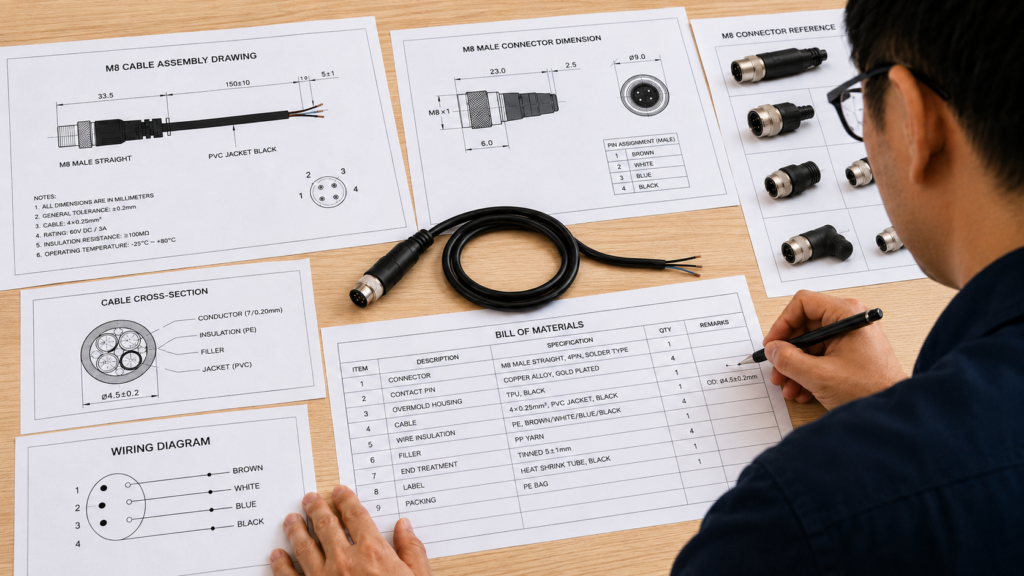
The strongest RFQ usually starts with a controlled product drawing. It does not need to be visually complex, but it should show the complete cable assembly, connector orientation, cable length, dimensional reference points, tolerances, pinout, conductor colors, opposite-end preparation, labels and molded features.
A useful project package may include:
- Assembly drawing
- Point-to-point wiring table
- BOM
- Connector datasheet
- Equipment interface drawing
- Existing supplier part number
- Approved sample record
- Product photographs
- Inspection specification
- Packaging specification
- Customer SKU or internal part number
When several files are provided, the buyer should clearly identify the latest revision and the controlling document. A physical sample may show one cable length, while the latest drawing specifies another. A photograph may show a right-angle connector, while the BOM refers to a straight connector. Without revision control, the supplier may quote one version and prepare a sample based on another.
Physical samples are especially useful for replacement or redesign projects. They can help the manufacturer review connector fit, cable flexibility, overmold appearance, strain relief, label position and packaging method. However, a sample does not always reveal conductor size, shielding coverage, insulation material, contact termination or internal wiring without further analysis.
The buyer should also state whether the existing sample must be duplicated, improved or used only as a functional reference. This distinction matters when the previous design has weaknesses such as insufficient strain relief, unsuitable cable stiffness, unclear labeling or poor connector protection.
Application and Equipment Context
A cable assembly cannot be evaluated properly without understanding where it will be used. The manufacturer needs to know what the cable connects, what electrical function it performs, where it is installed and how it behaves during equipment operation.
Compare these two descriptions:
“Used in industrial equipment.”
“Connects a photoelectric sensor to a fixed control enclosure inside an automated packaging machine, with occasional exposure to lubricating oil.”
The second description gives the manufacturer enough context to review jacket material, movement, routing, shielding and connector protection.
A useful application description should identify:
- Equipment type
- Connected device
- Cable function
- Installation location
- Fixed or moving condition
- Routing space
- Environmental exposure
- Consequence of connection failure
- Target service expectations
An M8 female cable connected to a fixed proximity sensor inside a protected enclosure may not require the same structure as one routed through a moving machine section. The moving cable may need finer conductor stranding, a more suitable jacket, controlled bend radius and stronger strain relief.
Application information also allows the manufacturer to challenge unsuitable specifications before they become purchasing problems. A requested material may be familiar to the buyer but inappropriate for the actual movement, temperature or chemical exposure.
Missing Drawings and Controlled Assumptions
A missing drawing does not always prevent an initial quotation. Buyers can start with clear connector photographs, mating-interface information, cable length, pin count, wiring details, application conditions, target quantity and an existing sample.
Connector photographs should show:
- Front mating face
- Side profile
- Thread and coupling structure
- Key position
- Cable exit
- Overmold shape
- Existing labels
- Opposite-end preparation
A dimensional reference in the photograph may help with preliminary evaluation, but photographs should not replace a controlled drawing for production.
When information is incomplete, the quotation should state its assumptions. For example:
- Four-position M8 female connector
- A-coded interface
- Straight molded body
- Three-meter cable
- Unshielded PUR jacket
- Open-wire opposite end
- Standard bulk packaging
- No custom tooling
If one of these points changes, the price, MOQ or lead time may also change.
This is not a weakness in the quotation. It is a practical way to make uncertainty visible. It helps the buyer understand exactly what has been priced and which decisions must be completed before sampling.
Quote Readiness and Internal Alignment
Before sending an RFQ, procurement and engineering teams should confirm that they are describing the same product.
Common internal inconsistencies include:
- Engineering requires shielded PUR, but purchasing sends an old PVC drawing.
- The sample uses a right-angle connector, but the inquiry requests a straight connector.
- The annual forecast includes five cable lengths, but the RFQ lists only one.
- The pinout table and connector-face drawing use different viewing directions.
- Packaging requirements are known by logistics but absent from the inquiry.
A quote-ready RFQ should identify the current revision, project stage, expected quantity and unresolved questions. This makes supplier comparison more meaningful.
The lowest unit price may exclude custom terminals, testing, labels, packaging or connector protection included by another supplier. Unless the quotation basis is aligned, procurement is comparing different products rather than different manufacturers.
| RFQ input | Minimum information | Preferred information | Quotation impact |
| Product definition | Product name and basic configuration | Controlled drawing with revision | Defines the product being quoted |
| Connector | M8 female and pin count | Coding, orientation, mating part and source preference | Affects compatibility and sourcing |
| Cable | Length and basic material | AWG, core count, OD, jacket, shield and tolerance | Affects material and processing cost |
| Wiring | Basic pin assignment | Point-to-point table with viewing direction | Prevents incorrect or mirrored pinout |
| Application | General equipment use | Function, movement, environment and routing | Supports material and structure review |
| Testing | Continuity requirement | Test method, quantity, limits and reports | Affects inspection time and cost |
| Quantity | Initial order quantity | Sample, pilot, annual forecast and release plan | Affects MOQ and material planning |
| Packaging | Bulk or individual | Labels, barcode, coil size and protection | Affects labor, material and freight |
| Timeline | Requested delivery date | Sample, approval, production and shipment dates | Identifies schedule dependencies |

Which M8 Female Connector Details Must Be Confirmed?
The M8 connector must be defined by its coding, pin count, contact gender, viewing direction, orientation, mating component, shielding, sealing, overmolding and opposite-end termination. The words “M8 female” alone do not confirm mechanical compatibility or electrical function. Exact identification prevents fit problems, mirrored pinouts, sourcing changes and sample revisions.
Connector Identity and Mating Compatibility
An M8 female connector normally contains socket contacts, but gender wording alone is not enough to guarantee compatibility.
The RFQ should confirm:
- Thread and coupling structure
- Connector coding
- Key position
- Contact count
- Mating component
- Contact-face orientation
- Connector body orientation
- Shield continuity requirement
- Sealing requirement
The safest approach is to provide the mating connector part number, device interface drawing or equipment model. For replacement projects, clear front-face and side photographs can help, but a verified part number is more reliable.
The pinout drawing must state whether it is viewed from the mating face or the cable-entry side. A mirrored wiring interpretation is a common and expensive mistake. The finished cable may look correct and still connect the wrong circuits.
When the buyer specifies a branded connector or exact part number, the quotation should clarify whether that exact component is included. If an alternative is proposed, the manufacturer should review mechanical fit, contact arrangement, material, rating, sealing and availability before the substitution is approved.
Availability is also a technical-commercial issue. A suitable connector may have a high purchasing minimum, long lead time or limited long-term supply. Confirming this before sampling can prevent a successful sample from becoming difficult to reproduce in volume.
Coding, Pin Count and Contact Assignment
M8 connectors are available in several contact arrangements. Three- and four-position versions are common in sensor and actuator applications, while six-, eight- and higher-position configurations may be used when more circuits are required.
The selected configuration must match the equipment interface. Coding and keying prevent incompatible connectors from mating and should be stated explicitly.
The number of contact positions does not always equal the number of active conductors. A four-position connector may use only three circuits, leave one position unused or include a special internal connection.
Each contact should therefore be identified as:
- Active
- Unused
- Reserved
- Bridged
- Grounded
- Connected to shield
- Connected to a defined terminal
The RFQ should include a point-to-point wiring table. Signal descriptions such as supply, ground, switching output, analog signal, communication line or unused are more useful than pin numbers alone.
Conductor colors should also appear in the approved specification. Common color conventions may be useful during discussion, but they should not replace a project-specific wiring document.
Straight, Angled and Opposite-End Design
A straight connector is usually suitable where there is enough axial clearance and the cable can leave the device without an immediate change in direction.
A right-angle connector may be preferred when:
- Equipment space is limited
- The cable must route along a housing
- Axial clearance is restricted
- A straight cable exit would create excessive bending
- The connector must sit close to a machine frame
The exit direction of a right-angle connector must be shown relative to the connector key. “Right angle” alone may be ambiguous because the cable can visually point in different directions depending on the viewing position.
The opposite end also requires complete definition. Possible constructions include:
- Open cable end
- Stripped conductors
- Stripped and tinned conductors
- Ferrules
- Crimp terminals
- Another M8 connector
- M12 connector
- Board connector
- Valve connector
- Custom equipment interface
For an open end, specify jacket strip length, conductor strip length, tinning, ferrules, terminals, heat shrink and wire labels.
For a double-ended cable, both connectors and the complete point-to-point wiring relationship must be defined.
One supplier may quote a simple cut cable, while another includes terminals, heat shrink, labels and testing. These are not equivalent quotations.
Sealing, Shielding and Overmolding
A request for a “waterproof M8 cable” is incomplete unless the buyer states the required protection level, exposure condition, mating state and test method.
Published IP ratings normally apply to a specific mated connector system under defined conditions. The male and female parts must be compatible, correctly mated and properly tightened. Cable entry, overmold, seals and opposite-end construction may also affect the performance of the finished assembly.
Shielding must be reviewed at the connector level. The RFQ should define:
- Foil, braid or combined shielding
- Shield coverage expectation
- Drain wire requirement
- Connector housing termination
- One-end or two-end grounding
- Chassis connection
- Shield isolation requirements
Overmolding may improve:
- Connector protection
- Strain relief
- Cable-exit control
- Sealing structure
- Appearance consistency
- Repeatable production
A custom overmold may require tooling when the buyer requests a special shape, logo, color, hardness, cable exit or strain-relief design.
The quotation should distinguish between a standard molded connector and a custom molded structure because tooling, sample time, MOQ and production cost may differ substantially.
| Connector decision | Common options | What must be confirmed | Risk if omitted |
| Contact gender | Female socket interface | Mating connector and face view | Wrong mating component |
| Coding | A-coded or project-defined | Equipment interface and keying | Connector will not mate |
| Pin count | 3, 4, 6, 8 or project-defined | Active and unused contacts | Wrong circuit capacity |
| Orientation | Straight or right angle | Exit direction relative to key | Installation interference |
| Opposite end | Open wire, terminal, M8, M12 or custom | Strip lengths, terminals and second interface | Incomplete quotation |
| Shielding | None, foil, braid or combined | Shield termination and grounding | Poor interference control |
| Sealing | Indoor, splash, washdown or defined IP target | Mated system and test method | Unsupported waterproof claim |
| Overmolding | Standard or custom | Shape, material, color, logo and tooling | Cost and sample changes |
| Connector source | Specified source or approved alternative | Availability and approval process | Delay or unapproved substitution |

Which Cable Specifications Affect the Quote?
Cable length, tolerance, conductor size, core count, insulation, jacket, outer diameter, shielding, flexibility, electrical function, pinout and color all affect the quotation. These specifications determine material usage, connector compatibility, production method, testing and durability. Two cables of equal length may have very different constructions and costs.
Length, Tolerance and Measurement Method
Cable length should be defined using clear reference points. The drawing should state whether the dimension is measured between:
- Connector faces
- Overmold exits
- Cable exits
- Terminal ends
- Cut-wire ends
- Defined datum points
This matters because connector bodies, overmolds and stripped sections change the usable routing length.
A three-meter overall assembly is not necessarily the same as three meters of exposed cable between two molded connectors.
Tolerance should reflect the application. Equipment with fixed routing channels may need tighter length control than a general replacement cable. However, unnecessarily narrow tolerances can increase cutting control, measurement time, segregation and inspection cost without improving field performance.
Multi-length programs should use separate SKUs and a controlled matrix. Different part numbers may be required when any of the following changes:
- Cable length
- Connector orientation
- Pinout
- Jacket color
- Label
- Packaging
- Opposite-end preparation
Longer cables also affect electrical resistance, voltage drop, signal behavior, coil diameter, carton size and freight volume. In some signal applications, increasing the cable length may require additional technical review rather than a simple material-cost adjustment.
Conductor Size and Internal Structure
The RFQ should state:
- Conductor count
- AWG or square-millimeter size
- Copper type
- Strand construction
- Insulation material
- Cable outer diameter
- Filler or tape requirements
- Shield and drain-wire structure
Compact M8 sensor cables commonly use relatively small conductors. A range around 0.14 to 0.34 mm², approximately 26 to 22 AWG, is often seen in commercial products, but it is not a universal specification.
The correct conductor size depends on:
- Current
- Voltage drop
- Cable length
- Contact capacity
- Flexibility
- Temperature
- Connector entry size
- Applicable project requirements
A larger conductor may reduce voltage drop and support higher current, but it can increase cable diameter and may not fit the selected connector or mold.
A smaller conductor can improve compactness and flexibility, but it may not be suitable for the electrical load.
Stranding is especially important in moving applications. Fine-stranded conductors are generally more flexible, but continuous movement performance depends on the complete cable construction, including insulation, shield, jacket and lay length.
Fillers, tapes and shield layers affect cable roundness, stripping and molding. The cable must be suitable for consistent cutting, stripping, termination, overmolding and electrical testing.
Electrical Function, Pinout and Wire Colors
The manufacturer needs to know the function of each conductor.
An M8 cable may carry:
- Sensor supply
- Ground
- Digital switching signal
- Analog signal
- Communication
- Actuator current
- Combined power and signal
Operating voltage and current affect conductor size, insulation review, contact suitability and testing.
Signal type may affect:
- Shielding
- Conductor arrangement
- Capacitance
- Grounding
- Noise immunity
- Maximum practical length
The RFQ should include a point-to-point table showing the M8 contact, conductor color, circuit function, opposite-end connection, polarity and unused contacts.
The connector viewing direction should appear on the same controlled drawing.
Wire colors should be specified rather than assumed. Different connector families, cable manufacturers, contact counts and customer standards may use different color assignments.
For long-term production, material revisions should also be controlled. A change of cable source may affect:
- Color shade
- Jacket hardness
- Diameter
- Printing
- Stranding
- Flexibility
- Stripping behavior
Even when nominal specifications appear equal, an alternative material should be reviewed before mass production.
Jacket Material and Shielding Structure
PVC and PUR are common jacket choices for M8 sensor and actuator cables, but neither is automatically correct for every application.
PVC is frequently used in fixed or moderate-duty industrial installations because it can provide practical processing, general handling and cost performance.
PUR is often considered where abrasion, oil exposure, movement or tougher industrial use is important.
Actual performance depends on the specific material formulation and supporting supplier documentation.
The RFQ should describe the required performance rather than naming a material without application context. Relevant conditions include:
- Flexibility
- Abrasion
- Oil exposure
- Chemical exposure
- Temperature
- Outdoor use
- Flame-performance requirements
- Color
- Outer diameter
- Target market
Shielding may use foil, braid or both.
Foil can provide high coverage in a compact structure. Braid can provide mechanical stability and low-resistance shield continuity. A combined shield may be used for more demanding interference-control requirements.
The shield also requires a termination plan. The manufacturer must know whether it connects to:
- Connector housing
- Drain wire
- Chassis
- Terminal
- Both connector ends
- One connector end
- No connector end
Shielding without a defined grounding strategy may add cost without achieving the intended electrical benefit.
| Cable parameter | Common range or option | Selection value | Quotation concern |
| Finished length | Short equipment lead to multi-meter cordset | Matches installation routing | Material, resistance and packaging |
| Length tolerance | Drawing-defined | Controls installation fit | Cutting and inspection effort |
| Conductor size | Often around 0.14–0.34 mm² in compact sensor cables | Balances current, flexibility and diameter | Copper cost and connector fit |
| Core count | Commonly 3 or 4; higher where more circuits are needed | Matches active contacts | Cable construction complexity |
| Cable OD | Often around 4–6 mm for compact M8 cordsets | Must fit connector and routing space | Mold compatibility |
| Jacket | PVC, PUR or project-specific | Matches environment and movement | Material and sourcing cost |
| Shield | None, foil, braid or combined | Controls interference | Material and termination labor |
| Conductor color | Standard or customer-defined | Supports installation and testing | Material control |
| Pinout | Point-to-point wiring table | Prevents electrical mismatch | Production and test-fixture setup |
| Flexibility | Fixed, occasional flex, continuous flex or torsion | Matches machine movement | Construction and validation |

How Do Application and Testing Affect Pricing?
Application and testing affect pricing because they determine material selection, cable construction, molding, process control, inspection time, documentation and sample validation. A fixed indoor sensor cable may require routine electrical checks, while a moving, shielded, sealed or harsh-environment cable may require specialized materials, tooling and project-specific testing.
Function, Movement and Failure Risk
An M8 cable used for a basic position sensor does not have the same design priorities as one used for an actuator, analog signal, communication circuit or critical machine function.
The buyer should explain what the cable carries and what happens if the connection becomes unstable.
A failure that creates a maintenance warning is different from one that stops a production line or affects a critical equipment function.
Movement should also be defined precisely. The cable may be:
- Fixed after installation
- Moved during maintenance
- Repeatedly flexed
- Routed in a drag chain
- Twisted around a robotic axis
- Exposed to continuous vibration
The word “flexible” is not enough.
A cable may feel soft by hand but still be unsuitable for repeated movement. Useful motion information includes:
- Minimum bend radius
- Travel distance
- Movement speed
- Acceleration
- Torsion angle
- Cable-guide method
- Expected service cycles
These conditions affect conductor stranding, jacket, shield, diameter, connector orientation and strain relief.
A right-angle connector may improve installation clearance but create a different bend pattern at the cable exit. The whole cable-routing system should therefore be considered.
Environmental Exposure and Material Choice
Environmental requirements should describe actual exposure rather than rely on broad terms such as industrial, waterproof, oil-resistant or heavy duty.
Temperature information should include:
- Normal operating temperature
- Minimum temperature
- Maximum temperature
- Whether the cable moves at those temperatures
- Storage conditions
Moisture exposure should distinguish among:
- Condensation
- Occasional splash
- Washdown
- High humidity
- Temporary immersion
- Continuous immersion
Chemical exposure should identify the substances where possible. Oil, coolant, cleaning agents, acids, alkalis and solvents may affect cable jackets and connector components differently.
Mechanical exposure may include:
- Abrasion
- Pulling
- Crushing
- Vibration
- Impact
- Contact with moving machine parts
Outdoor use may add UV, rain, corrosion and temperature cycling.
The jacket, insulation, connector body, contacts, seals, overmold and metal hardware should be reviewed as one system. A durable jacket cannot compensate for an unsuitable connector seal or weak cable transition.
When the environment is uncertain, sample trials or defined validation tests are more useful than unsupported performance claims.
Electrical and Mechanical Test Planning
Testing should focus on the failure modes that matter for the project.
Routine checks for many M8 cable assemblies include:
- Continuity
- Short-circuit check
- Wire sequence
- Pinout
- Polarity
- Connector fit
- Appearance
- Labeling
- Packaging
Continuity and pinout checks are often suitable for every finished assembly because they can detect open circuits, shorts and wrong wiring.
Mechanical and environmental tests are often sample-based or project-based because they may be destructive or time-consuming.
Pull-force testing may be used to evaluate terminal or cable-to-connector strength.
Insulation or hi-pot testing may be considered where electrical safety requirements justify it.
Bending or swing testing may be relevant for moving cables.
Temperature, humidity, salt spray or sealing tests may be needed for harsher conditions.
The RFQ should define:
- Test method
- Number of samples
- Acceptance criteria
- Applicable standard
- Report requirement
- Approval authority
A long list of available laboratory equipment is not a substitute for a suitable test plan. The goal is to match inspection effort to real product risk.
Compliance, Records and Reporting
Compliance requirements may affect the BOM, cable material, connector source, labeling, testing and document collection.
The buyer should identify:
- Destination market
- Equipment category
- Customer-specific requirements
- Required declarations
- Required material documents
- Required test records
- Traceability requirements
- Third-party testing needs
A supplier declaration, material report, inspection record, third-party test report and product certification are different documents.
The RFQ should state which one is required.
When a formal report is needed, the buyer should define:
- Report format
- Language
- Lot number
- Required measurements
- Sample identification
- Approval process
A custom cable assembly should not automatically be described as compliant with every certification because a similar raw material has a document. Compliance depends on the final product configuration, material source, target market and applicable requirements.
| Test or review | Typical use | Common inspection level | Acceptance basis |
| Continuity | Detects open circuits and shorts | Commonly every finished assembly | Approved wiring diagram |
| Pinout and sequence | Confirms contact-to-wire mapping | Commonly every finished assembly | Point-to-point table |
| Polarity | Confirms positive, negative and ground circuits | Every applicable assembly | Electrical drawing |
| Connector fit | Confirms mating and locking | First article, sample or lot-based | Approved mating component |
| Dimensional inspection | Confirms length, strip and mold dimensions | First article and lot-based | Drawing tolerances |
| Pull-force test | Evaluates terminal or joint strength | Sample or lot-based | Agreed method and limit |
| Insulation or hi-pot | Reviews insulation performance | Project-based | Customer or applicable standard |
| Bending or swing | Reviews repeated-motion durability | Development samples | Agreed cycles and failure criteria |
| Temperature and humidity | Reviews environmental stability | Project-based | Agreed condition and duration |
| Sealing test | Reviews waterproof-related performance | Project-based | Defined mated system and method |
| Appearance and labeling | Confirms workmanship and identification | Commonly every assembly | Approved sample and label file |
| Packaging inspection | Confirms quantity and protection | Every shipment lot | Packaging specification |

How Can Buyers Submit a Quote-Ready RFQ?
A quote-ready RFQ combines technical specifications with commercial information. It should include sample and production quantities, annual forecast, tooling needs, packaging, labels, required dates, destination and open assumptions. This allows the manufacturer to review sourcing, engineering, production, testing and export delivery as one project.
Quantity, MOQ and Release Planning
The buyer should separate the project into realistic stages:
- Engineering sample
- Validation sample
- Pilot order
- First production order
- Repeat production
- Annual supply program
Each stage affects cost differently.
Samples may require:
- Engineering review
- Manual preparation
- Small connector purchases
- Tool trials
- Additional inspection
- Special packaging
- Express delivery
A pilot order can help confirm:
- Production stability
- Label accuracy
- Packaging
- Assembly fit
- Field installation
- Batch inspection
- Shipping preparation
The first production quantity should reflect a realistic requirement rather than an artificial volume used only to obtain a lower price.
Annual forecasts help the manufacturer review material planning, connector sourcing and capacity. However, forecasts should be identified as estimates unless the buyer is making a formal purchasing commitment.
The number of SKUs also affects cost. Five similar cables with different lengths, pinouts and labels may require more material control, setup and inspection than one high-volume SKU.
For many custom cable projects, MOQ may start from approximately 500 pieces, while the final requirement can depend on:
- Connector type
- Cable structure
- Custom extrusion
- Material color
- Shielding
- Overmolding
- Tooling
- Packaging
- Purchased-component minimums
A useful quotation can show prices at several realistic volume levels and identify which costs are one-time, recurring or quantity-dependent.
Tooling and Sample Development
Custom tooling may be required for:
- Special overmold shape
- Custom cable exit
- Strain-relief profile
- Logo
- Connector shell
- Sealing structure
- Protective geometry
The RFQ should clarify whether the product may use an existing standard mold or requires a custom design.
Tooling should normally be quoted separately from unit price so the buyer can distinguish one-time investment from recurring manufacturing cost.
Before tooling is approved, the manufacturer may need to review:
- Connector dimensions
- Cable diameter
- Material shrinkage
- Cable positioning
- Mold flow
- Sealing surfaces
- Strain relief
- Logo detail
- Expected production volume
The sample plan should define what the customer will approve, such as:
- Connector fit
- Pinout
- Cable length
- Flexibility
- Overmold appearance
- Color
- Label
- Packaging
- Test results
An approved sample is most useful when it is linked to a final drawing and specification.
A sample without controlled documentation creates uncertainty when materials, drawing revisions or suppliers change.
Sample revision should be treated as risk reduction. Correcting cable stiffness, label position, overmold shape or wire preparation during development is far less expensive than correcting it after mass production.
Packaging, Labels and Export Delivery
Packaging should protect the connector, control bend radius, separate SKUs and support identification.
Long cables may require controlled coil diameters to prevent kinks.
Open conductors, terminals or exposed connector faces may require caps, wrapping, trays or separate bags.
Possible label information includes:
- Customer part number
- Manufacturer part number
- Barcode
- Batch number
- Wire number
- Cable identification
- Country of origin
- Carton mark
- Installation information
Multi-SKU programs require special attention. Cables with different lengths, angles or pinouts may look nearly identical after packing.
Identification methods may include:
- Individual SKU labels
- Color markers
- Separate bags
- Compartmented cartons
- Different coil ties
- Wire-number labels
- Barcode verification
Export delivery planning may include:
- Carton dimensions
- Carton weight
- Pallet requirements
- Shipping destination
- Transport mode
- Customs documentation
- Forwarder labels
- Customer routing marks
Packaging should be confirmed before mass production because it affects labor, materials, warehouse handling and freight cost.
Timeline and Final RFQ Control
A realistic timeline separates:
- Quotation
- Engineering review
- Connector confirmation
- Tooling
- Sample preparation
- Customer approval
- Material purchasing
- Mass production
- Inspection
- Packaging
- Shipment
“Urgent” is not a measurable requirement.
A more useful schedule states:
- Sample required date
- Approval target date
- Purchase-order date
- Mass-production completion date
- Shipment date
- Destination arrival requirement
The manufacturer should also identify dependencies that may affect the schedule, including:
- Connector availability
- Custom cable extrusion
- Color matching
- Tool development
- Customer approval
- Testing
- Documentation
- Packaging preparation
Before the purchase order is released, both sides should confirm:
- Drawing revision
- BOM
- Approved sample
- Quantity
- Unit price
- Tooling
- Test plan
- Packaging
- Labels
- Delivery terms
- Approved deviations
A controlled RFQ can later become the basis for the quotation, sample specification, purchase order, inspection plan and production file.
| RFQ category | Required buyer input | Manufacturer review | Purchase decision value |
| Project stage | Prototype, pilot, first order or repeat program | Engineering and production route | Separates sample and production pricing |
| Quantity | Quantity per SKU and annual forecast | MOQ, material minimum and capacity | Supports realistic price comparison |
| Tooling | Standard or custom overmold | Feasibility, cost and lead time | Separates one-time and recurring cost |
| Sample approval | Items to be checked | Function, appearance, drawing and packaging | Creates production reference |
| Test plan | Tests, limits, sample size and reports | Equipment, labor and validation time | Confirms equal quality scope |
| Packaging | Coil, bag, label, barcode and carton | Material, labor and protection | Prevents hidden packaging cost |
| Schedule | Sample, approval, production and shipment dates | Material and process dependencies | Reveals delivery risk |
| Destination | Country, factory, warehouse or forwarder | Documents, carton and shipping method | Supports export planning |
| Commercial terms | Currency, incoterm, payment and validity | Financial and logistics review | Supports landed-cost comparison |
| Final control | Approved drawing, BOM, sample and revision | Production-file release | Reduces sample-to-production mismatch |
Request an M8 Female Cable Assembly Quote
An accurate quotation should provide more than a unit price. It should show that the connector interface, cable structure, electrical function, application environment, testing, order volume, packaging and remaining risks have been understood.
Cablivo is the overseas-facing website brand of Shenzhen Tianxiaowei Electronics Co., Ltd., a Shenzhen-based custom cable, wire harness and cable assembly manufacturer.
The company supports project development from requirement review, drawing review, material selection and sampling through mass production, quality inspection, packaging and shipment coordination.
For an M8 female cable assembly project, buyers can submit:
- Product drawing or dimensional sketch
- Connector part number or connector photographs
- M8 coding and pin count
- Connector gender and orientation
- Mating connector information
- Cable length and tolerance
- AWG and conductor count
- Jacket and shielding requirements
- Pinout and wire sequence
- Voltage, current and signal information
- Application environment
- Cable movement requirements
- Testing and reporting requirements
- Sample and production quantities
- Annual forecast
- Packaging and labeling
- Target timeline
- Shipping destination
When complete documentation is not yet available, start with the drawing, sample photographs, connector information, cable length, application and target quantity.
The remaining specifications can be identified during engineering review and confirmed before sample production.
The purpose of the quotation is not simply to produce a fast number. It is to establish a clear and manufacturable product specification that can move from RFQ to sample approval and stable production with fewer hidden assumptions, fewer technical changes and better control of project risk.



