 Skip to content


A cable assembly quotation can look precise down to the last decimal place and still be based on the wrong product. With an M12-to-RJ45 project, a request such as “M12 to RJ45, 2 meters” leaves several engineering decisions unresolved. The M12 interface may use different coding, contact counts, gender and orientation, while the RJ45 end may require a particular shielded structure, boot or housing. The cable itself may differ in category, conductor size, pair count, shielding, jacket, flexibility and application environment. Pinout, data rate, PoE, test requirements, quantity and packaging can further change the actual construction and manufacturing cost.
An accurate M12-to-RJ45 cable assembly quote normally requires the M12 and RJ45 connector configuration, cable category and construction, finished length, pinout, network requirement, shielding, application environment, testing scope, target quantity, packaging requirements and any available drawing, BOM, connector part number or physical sample. Clear specifications reduce assumptions, make quotations easier to compare and lower the risk of discovering a mismatch after sampling.
The real cost of an incomplete RFQ is rarely the first quotation. It is the engineering time lost when a right-angle M12 connector points in the wrong direction, when a cable built for fixed installation is placed on moving equipment, or when the supplier prices one pinout while the machine requires another. A few missing details can turn a straightforward sourcing task into repeated technical emails, sample revisions and revised quotations. The purpose of a good RFQ is not to create paperwork. It is to remove the assumptions that cause expensive mistakes later.
What M12 and RJ45 Connector Details Are Required?
An accurate quotation should identify the M12 coding, contact count, gender, orientation and mating interface together with the RJ45 connector type, shielding and boot or housing requirement. Connector family names alone are not enough. The manufacturer needs to understand exactly what must mate with the equipment, how each connector is installed and whether either end has special mechanical or environmental requirements.
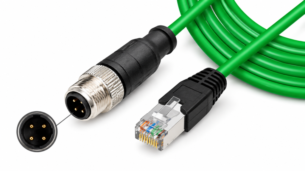
Is M12 D-Code or X-Code Required?
M12 coding changes more than the shape of the keyway. In industrial Ethernet applications, D-coded M12 interfaces are commonly encountered as four-position configurations for 100 Mbps networks using two data pairs, while X-coded M12 interfaces commonly use eight contacts and four pairs for higher-bandwidth Ethernet applications. In compliant CAT6A systems, X-coded configurations may be used for data rates up to 10 Gb/s. These are useful reference points, but they should never replace the equipment specification or approved drawing.
A higher-speed connector is not automatically the correct connector. If a PLC, machine I/O module, industrial camera, control system or existing switch interface uses D-code, a cable assembly still has to mate with that physical port. Moving to X-code would require a different equipment interface rather than simply selecting a “better” cable. The practical quotation sequence is therefore equipment interface first, network requirement second and cable construction third. When the coding is uncertain, provide the equipment model, connector part number, front-view port photograph or an existing cable sample so the connector can be identified before material is priced.
What Pin Count, Gender, and Orientation Are Needed?
The M12 side should state the contact count, male or female configuration and whether the connector is straight or right-angle. These points directly affect component selection and assembly structure, but orientation is often overlooked until the cable is physically installed. A 90-degree connector that exits toward a machine enclosure wall instead of along the intended routing path can make a technically correct assembly unusable. Where installation space is limited, the drawing should show both the key position and cable exit direction rather than relying only on the phrase “right-angle M12.”
Gender should also be checked against the actual mating connector. Product photographs are useful references, but a photograph taken at an angle can hide contact details or make similar connector shells difficult to distinguish. A connector part number, mating-component reference or clear front-view photograph provides stronger evidence. Where overmolding is required, the molded body size, grip area, strain-relief geometry and cable exit also need review because they can affect tooling, connector handling and installation clearance.
Which RJ45 Type Should Be Specified?
“RJ45” is not a complete quotation specification. The project may require a shielded or unshielded plug, a molded boot, a compact latch-protection design, a particular cable-diameter range or a ruggedized solution. The correct choice depends on where the RJ45 side is used. A standard RJ45 installed inside a protected control cabinet has a different environmental duty from an RJ45 end exposed beside machinery, outdoors or near washdown areas. The fact that an M12 connector is designed for a sealed industrial interface does not automatically make the RJ45 end equally protected.
Port density also matters. Large molded boots can provide useful strain relief and latch protection but may interfere with adjacent ports on tightly spaced industrial switches. A compact RJ45 body may fit better where several connections are installed side by side. Shielding should also be considered together with the cable structure. If the cable uses a shield and the project requires electrical shield continuity, the RJ45 termination needs to support the intended grounding approach rather than being selected independently from the rest of the assembly.
| Connector Item | Common Options | What to Confirm | Quotation Impact |
| M12 coding | D-code, X-code, project-specific | Equipment interface and network requirement | Changes connector and cable structure |
| Contact count | Commonly 4 or 8 in Ethernet applications | Drawing or mating interface | Changes termination and cable construction |
| Gender | Male or female | Mating connector on equipment | Prevents mechanical mismatch |
| Orientation | Straight or right-angle | Installation clearance and cable routing | Changes connector component and molding |
| RJ45 shielding | Shielded or unshielded | Cable shielding and EMC requirement | Changes plug and termination method |
| RJ45 boot | Molded, compact, latch-protected | Port spacing and strain relief | Affects mechanical design |
| Overmolding | Standard or custom profile | Drawing, sample and required strain relief | May require tooling and validation |
| Connector PN | Known or to be confirmed | Brand, series, source or approved alternative | Influences sourcing and lead time |
A useful connector specification therefore goes well beyond the phrase “M12 to RJ45.” It defines what must mate with the equipment, how both connectors are oriented, whether shielding must continue through the connector shells and whether either end faces space or environmental limitations. Confirming these details before quotation makes later sample approval much more meaningful because the sample is built against the real installation rather than against a supplier’s default interpretation.
Which Cable Specifications Affect the Quote?
Cable category, conductor gauge, pair count, shielding, jacket, outer diameter, finished length and flexibility all affect an M12-to-RJ45 quotation. The selected construction needs to satisfy both network performance and installation conditions. A technically higher category is not automatically a better choice if the finished cable becomes too large, too rigid or incompatible with the selected connectors and equipment routing.

What Cable Category and Data Rate Are Required?
The cable category should follow the actual equipment and network requirement rather than being chosen because a larger category number appears more impressive. Industrial Ethernet systems may operate at 100 Mbps, 1 Gb/s, 10 Gb/s or another defined system speed, and the M12 coding, pair count, connector structure and cable construction need to support the intended link together. D-coded M12 Ethernet is commonly used around 100 Mbps two-pair systems, while X-coded eight-contact interfaces are widely associated with four-pair Gigabit and higher-bandwidth applications, including compliant CAT6A systems designed for up to 10 Gb/s.
The complete network matters as much as the short cable assembly being quoted. Many standardized twisted-pair Ethernet channels use a 100-meter channel concept, but the allowable length and performance of any individual M12-to-RJ45 assembly depend on the entire connection architecture, patching, equipment, cable construction and applicable standard. A request for “high-speed industrial Ethernet cable” therefore leaves too much open to interpretation. A more useful RFQ identifies the required category or system speed and provides the equipment specification whenever the exact network configuration has already been established.
Which AWG, Pairs, Shielding, and Jacket Are Needed?
Conductor sizes around 22–26 AWG are commonly encountered across industrial Ethernet and patch-style cable constructions, although the final gauge should be selected according to the approved cable design, connector termination range, flexibility, PoE requirements, cable diameter and installation conditions. Pair count also affects cost and structure. A two-pair cable and a four-pair cable require different conductor counts, twisting processes, shielding arrangements and terminations, so quotations based on different pair structures should not be treated as equivalent.
Shielding may use foil, braid or combined constructions depending on the cable design and electromagnetic environment. In areas with servo drives, motors, switching power equipment or other interference sources, shield design deserves particular attention. Jacket selection should follow the application as well. PVC is common for general-purpose applications, while PUR is often considered where abrasion, oil exposure or tougher industrial handling matters. TPE and other materials may be chosen when flexibility or other specific performance characteristics are required. The correct material grade should be confirmed from the real operating conditions instead of being assigned generically to every industrial cable.
How Should Cable Length and Flexibility Be Defined?
Finished length should be measured between clearly defined reference points. Two companies can both describe a cable as “2 meters” while measuring from different locations on the connectors. In compact machine installations, that difference may determine whether the cable reaches the equipment or leaves excessive slack. A drawing should therefore show the measurement datum and any required tolerance. If the installation is not dimensionally sensitive, a commercial tolerance may be acceptable, but the manufacturer should not make that decision without understanding the assembly requirement.
Flexibility needs similar context. A cable that bends once during installation and remains fixed is fundamentally different from one moving thousands of times on a machine axis. For moving applications, useful RFQ information includes bend radius, approximate movement frequency, whether the motion is repetitive, whether torsion occurs and how the cable is supported. These details can influence conductor stranding, shielding design, jacket material and strain relief. A generic request for a “flexible cable” does not tell an engineering team whether the requirement is easy handling during installation or continuous movement during machine operation.
| Cable Variable | Common Reference or Option | Key Selection Question | Quotation Value |
| Data rate | 100 Mbps, 1 Gb/s, 10 Gb/s depending on system | What does the equipment require? | Helps define category and pair structure |
| Pair count | Commonly 2 or 4 pairs | Which M12 coding and Ethernet architecture are used? | Changes conductor count and termination |
| Conductor gauge | Often around 22–26 AWG in many industrial/patch designs | Is flexibility, PoE or compact OD important? | Changes copper content and cable diameter |
| Shielding | Unshielded, foil, braid, combined | What EMC environment does the cable face? | Changes material and manufacturing process |
| Jacket | PVC, PUR, TPE or project-defined | Static, moving, oil-exposed or outdoor? | Influences durability and material cost |
| Cable OD | Construction-dependent | Is connector or routing space restricted? | Affects connector compatibility |
| Color | Standard or custom | Is equipment identification required? | May change material preparation |
| Cable printing | None or customer-defined | Are part numbers or cable markings required? | Adds printing and inspection |
The goal is not to specify the most expensive conductor, shield and jacket combination available. It is to choose a construction that meets the actual electrical and mechanical requirements without adding unnecessary cost or creating new installation problems. A well-defined cable specification also makes quotations more comparable because different manufacturers are pricing the same structure rather than making different assumptions about category, shielding and material.
How Should Wiring and Network Requirements Be Defined?
The RFQ should define the M12-to-RJ45 pin mapping, network or protocol requirement, target data rate, PoE requirement where applicable and the intended shield termination. A cable can use the correct connectors, length and jacket while still failing in the equipment if its internal wiring or grounding arrangement does not match the approved system design.

What Pinout Maps M12 to RJ45?
The safest pinout is the one approved for the actual equipment. A generic diagram found online may describe a common M12-to-RJ45 arrangement, but it should not replace a machine drawing, system specification, existing validated sample or equipment manual. The connectors can look correct and mate perfectly while the internal contact mapping is wrong. That kind of error is difficult to identify from appearance alone and is one of the main reasons pinout information should be available before production material is released.
A useful pinout document shows each M12 contact and the corresponding RJ45 contact. Wire colors can be included as a manufacturing reference, but electrical contact mapping is more reliable than color alone because custom cable constructions may use different insulation colors or conductor arrangements. Replacement projects deserve particular care. An old cable described informally as “M12 to RJ45” may use a machine-specific wire map rather than the arrangement a new supplier expects. Where a drawing is unavailable, continuity analysis of an approved sample can help establish the mapping, but the resulting pinout should still be documented and approved before mass production.
Is PoE or a Specific Ethernet Protocol Required?
The application should state whether the assembly is being used for standard Ethernet, PROFINET, EtherCAT or another defined industrial network. The protocol information helps the manufacturer interpret the data-rate, connector and cable requirements more accurately. A short description such as “100 Mbps PROFINET between machine I/O and a cabinet switch, no PoE” gives an engineering team far more useful information than simply requesting an “industrial Ethernet cable.”
PoE needs separate attention because the cable may carry power and data at the same time. Depending on the implementation, conductor gauge, pair utilization, cable length, connector design and temperature rise may become more important. A cable that works for ordinary data transmission should not automatically be assumed suitable for every PoE application. If the equipment specification identifies the PoE class, power requirement or relevant standard, include it with the RFQ so the conductor and connector structure can be checked before the quote is finalized.
How Should Shield Continuity Be Defined?
Shielding should be treated as a complete path rather than a yes-or-no cable option. The cable shield, M12 shell, RJ45 shield and equipment grounding arrangement may all affect the final system. Foil, braid or combined shielding can be selected according to the approved cable design, but the termination at both connectors also needs definition. Where 360-degree shield contact through the connector housing is required, it should be stated on the drawing or in the specification rather than assumed from the word “shielded.”
Continuity testing can verify whether the intended shield path is electrically connected, but it does not replace a complete EMC evaluation of the machine. If the equipment uses a special grounding strategy, such as a different shield termination at one end, that arrangement needs to be identified before assembly. Reviewing these details during quotation and sampling is far less costly than discovering grounding or communication problems after the cable has already entered production.
| Network Requirement | Useful RFQ Input | Risk if Missing | Typical Verification |
| Pinout | M12-contact-to-RJ45-contact map | Incorrect wiring | Wire-map and continuity check |
| Protocol | Ethernet, PROFINET, EtherCAT or project-defined | Wrong performance assumption | Equipment-specification review |
| Data rate | 100 Mbps, 1 Gb/s, 10 Gb/s or defined requirement | Under- or over-specified cable | Match system and cable construction |
| PoE | Yes/no and equipment requirement | Power-related conductor requirement missed | Electrical specification review |
| Pair count | 2-pair or 4-pair | Wrong cable structure | Drawing and BOM confirmation |
| Shielding | Foil, braid, combined or project-defined | EMC inconsistency | Structure review |
| Shield termination | Shell-to-shell or drawing-defined | Grounding mismatch | Shield continuity check |
| Test scope | Wire map, network, shield or customer specification | Incomparable supplier quotations | Agree acceptance before pricing |
Defining the wiring and network requirements also improves quotation comparison. Two suppliers may offer very different prices because one assumes a basic two-pair D-coded assembly while another assumes a four-pair X-coded CAT6A structure with shield continuity and more extensive testing. Without a pinout, network requirement and test scope, both quotes can appear to describe the same product even though the manufacturing content is substantially different.
What Application and Test Requirements Matter?
The manufacturer needs to know where the cable will be installed, whether it moves and what environmental conditions it faces, together with the inspections or tests required for acceptance. An assembly inside a protected cabinet and one mounted beside moving, oil-exposed machinery may use similar connectors but require different cable materials, shielding, strain relief and validation.

Where Will the Cable Be Installed?
Application information often explains technical requirements that cannot be understood from the cable drawing alone. M12-to-RJ45 assemblies may be used between machinery and control cabinets, PLC or I/O systems, industrial cameras, automation equipment, communication cabinets, conveyors, packaging machines and other Ethernet-connected equipment. The manufacturer should know which end is exposed and which end remains protected because the environmental expectations of the M12 side and RJ45 side may be completely different.
Routing conditions are equally important. A cable permanently secured inside a cabinet does not experience the same mechanical stress as one routed along a moving axis, beside a motor drive or through a service area where technicians repeatedly handle it. Nearby electromagnetic noise can influence shielding decisions, while movement can affect conductor, jacket and strain-relief selection. Oil, coolant, cleaning chemicals, vibration, sunlight, dust and moisture should be mentioned only where they are relevant, but omitting a condition that materially affects the cable can cause a supplier to price a construction that is not appropriate for the real installation.
What Environmental Requirements Apply?
Environmental requirements should be defined from the installation rather than copied from a generic industrial-cable specification. M12 connector systems are commonly available with sealed industrial protection when properly mated, but the exact IP rating belongs to the specific connector design and installation condition. A standard RJ45 plug used inside a protected cabinet may have very different ingress protection from the M12 side. Therefore, describing the entire cable as “waterproof” without defining both connector ends can create a false expectation.
Temperature, chemical exposure and movement require the same discipline. A cable close to a heat source may need a different jacket from one operating at normal factory temperature, while outdoor installation may add UV and weathering considerations. Oil resistance can also mean different things depending on the material and test standard. If a particular coolant, lubricant or cleaning process is known, identifying it provides better engineering information than simply requesting an “oil-resistant industrial cable.” Technical values such as exact temperature range, IP level and material grade should be tied to a confirmed product specification rather than inserted as generic performance claims.
Which Tests Are Required?
“100% tested” sounds reassuring but has little value unless the test is defined. For M12-to-RJ45 cable assemblies, production checks may include continuity, wire-map verification, cable length, connector fit, shield continuity, appearance, labeling and packaging. Network-oriented projects may also require transmission-related testing against an agreed category or customer specification. If a particular analyzer, test standard, frequency range or report format is required, it should be included in the RFQ because different test scopes can produce very different quotation costs.
Mechanical and environmental tests should be selected according to real project risk rather than added indiscriminately. Pull-force testing may be useful for evaluating termination strength, while repeated bending can be relevant for moving assemblies. Connector insertion and withdrawal testing may be considered where frequent mating is expected. Temperature/humidity or corrosion-related tests may be appropriate in harsher environments. Cablivo’s documented manufacturing and quality scope includes project-based electrical, connector, mechanical and environmental testing discussions, with final requirements confirmed according to the cable type and application rather than assumed for every product.
| Test Area | Typical Purpose | Useful Application | RFQ Detail to Define |
| Continuity | Detect opens and shorts | Most cable assemblies | Conductors and acceptance criteria |
| Wire map | Confirm correct contact mapping | Custom M12-to-RJ45 wiring | Approved pinout |
| Shield continuity | Verify intended shield path | Shielded industrial Ethernet | Connector-to-connector requirement |
| Cable length | Verify dimensional compliance | Tight machine installations | Nominal length and tolerance |
| Connector fit | Check mating compatibility | New or replacement projects | Mating part or equipment interface |
| Transmission test | Evaluate Ethernet performance | Category-controlled data links | Standard and limits |
| Pull-force test | Evaluate mechanical attachment | High-stress terminations | Test point and acceptance value |
| Bending test | Evaluate repeated movement | Moving machinery | Bend radius, cycles and load |
| Environmental test | Evaluate temperature, humidity or corrosion exposure | Harsh applications | Test condition and duration |
| Label inspection | Verify project identification | Multi-SKU programs | Artwork, barcode and position |
| Packaging inspection | Prevent shipping damage or packing errors | Export orders | Coil, protection and carton method |
A useful test plan focuses on the failure modes that matter in the application. Testing every possible parameter can increase cost without improving the project, while testing too little can leave important risks unverified. Defining the acceptance criteria before quotation allows engineering, quality and purchasing teams to understand exactly what the price includes and prevents a vague test requirement from expanding after the sample has already been approved.
What Should Be Included in the RFQ?
A complete M12-to-RJ45 RFQ combines engineering information with purchasing requirements. Drawings, connector references, pinout, cable specification, application, testing, target quantity, sample needs, packaging, compliance and shipping information should be included where available. The project does not need to be perfectly documented on day one, but confirmed specifications should be clearly separated from open points that still require review.

Do Drawings, BOMs, or Connector Part Numbers Exist?
The strongest RFQ starts with the evidence that already exists. A dimensioned drawing can define finished length, connector orientation, pinout, tolerances, labels and material references, while a BOM can identify the connector series, cable construction, overmold material, labels and packaging components. Exact connector part numbers are particularly useful because they remove uncertainty around coding, contact arrangement, cable-diameter range, housing style and mating compatibility before the supplier begins sourcing.
A project can still move forward when a complete drawing is unavailable. Replacement programs often begin with an existing cable, clear connector photographs, equipment-port images, an old specification or a machine manual. The sample can be measured and its pinout evaluated, then the result can be documented for approval before production. Cablivo’s project-support fact base includes requirement review, drawing review, sample review, BOM review, connector confirmation, wire-sequence confirmation, pinout review and sample development, allowing incomplete project information to be organized before sampling rather than ignored.
What Quantity and Project Stage Should Be Provided?
Target quantity affects connector purchasing, raw-material preparation, tooling decisions, production setup, packaging and testing allocation, so the sample quantity and production quantity should be stated separately. An RFQ that requests five samples followed by a possible 2,000-piece production run provides far more commercial context than a request for only five cables. It also helps the manufacturer distinguish engineering prototypes from long-term production items and assess whether special material preparation or tooling is reasonable for the expected program.
Project stage should also be described. A new machine under engineering validation may still have open questions around connector orientation or material, while an assembly being transferred from an existing supplier may already have a released drawing, approved pinout, packaging artwork and test specification. Those projects require different levels of engineering review even when the final cable appears similar. Sample and production timing should therefore be confirmed after reviewing structure, connector availability, material preparation, tooling, test scope and packaging rather than being presented as one universal lead-time promise.
Are Packaging and Compliance Requirements Needed?
Packaging should be included in the RFQ whenever it affects the finished deliverable. Industrial cable assemblies may require individual bags, defined coil diameters, connector-protection caps, trays, labels, barcodes, inner cartons, private-label packaging or customer-specific outer-carton markings. A right-angle M12 connector can require different protection from a compact straight connector, while a long cable may need a larger coil to avoid excessive bending. These details influence labor, packing materials, carton size and export preparation.
Compliance requirements should be handled with the same care. The target market and any project-specific material, environmental or documentation requirements should be identified rather than assuming that every M12-to-RJ45 assembly carries every common certification. Cablivo’s fact base specifically requires certification and testing claims to be confirmed according to product type, project specification and target market instead of being applied automatically to all products. Shipping destination is also useful because labeling, export cartons, shipping documents and logistics planning can vary by project.
| RFQ Field | Example of Useful Information | Why It Matters |
| M12 connector | D-code, 4-pin, male, straight, PN if known | Confirms mating interface |
| RJ45 connector | Shielded plug with molded boot | Defines termination structure |
| Cable category | CAT5e, CAT6A or project-defined | Sets network target |
| Cable construction | Pair count, AWG, shield, jacket and OD | Defines materials and manufacturing |
| Finished length | 3,000 mm with defined tolerance | Controls cutting and installation fit |
| Pinout | Drawing or contact map | Prevents wiring mismatch |
| Network | Protocol and target data rate | Guides performance review |
| PoE | Yes/no and equipment requirement | Influences conductor review |
| Application | Machine, cabinet, outdoor, fixed or moving | Guides cable construction |
| Environment | Oil, water, temperature, vibration or flexing | Identifies durability requirements |
| Sample quantity | Prototype requirement | Supports sample planning |
| Production quantity | 500, 2,000, 10,000 pcs or project forecast | Supports sourcing and cost planning |
| Testing | Continuity, wire map, transmission or mechanical | Defines inspection scope |
| Labeling | PN, barcode, cable ID or lot information | Adds identification requirements |
| Packaging | Bag, coil, cap, carton or private label | Affects packing materials and labor |
| Compliance | Target market and project requirement | Prevents unsupported assumptions |
| Shipping destination | Country or delivery location | Supports export and logistics planning |
The difference between a weak and useful RFQ can be surprisingly small. “Please quote M12 to RJ45 cable, 3 meters, 1,000 pcs” forces the manufacturer to guess the coding, pair count, shielding, category, pinout, jacket, application and test scope. A request that specifies “M12 D-coded 4-position male straight to shielded RJ45, 3,000 mm finished length, fixed machine-to-cabinet installation, approved pinout attached, continuity and wire-map test required, five samples followed by 1,000 pieces” is only slightly longer but gives engineering, purchasing and quality teams a common technical starting point.
Preparing a More Accurate M12 to RJ45 Cable Assembly RFQ
A useful RFQ does not need to contain dozens of pages. It needs enough confirmed information to keep connector selection, cable construction, pinout, testing and packaging aligned with the actual application. When drawings are incomplete, a sample, connector photos, equipment information and known project conditions can still provide a practical starting point. The important distinction is between information that has been approved and information that remains open for engineering review.
Cablivo is the overseas-facing brand of Shenzhen Tianxiaowei Electronics Co., Ltd. and supports custom cable, wire harness and cable assembly projects through drawing and BOM review, connector and pinout confirmation, sample development, production preparation, testing, labeling, packaging and shipment coordination. Its documented project workflow is built around reducing specification uncertainty before sampling and mass production rather than treating a short product name as a complete manufacturing specification.
If you are preparing an M12-to-RJ45 cable assembly project, send the information you already have: the drawing, BOM, sample photos, connector references, finished length, pinout, application, target quantity, testing requirement and packaging plan. Missing items can then be identified and reviewed before the sample is produced. That approach makes the quotation easier to compare, gives the sample a clear acceptance basis and reduces the chance of connector, wiring, material or packaging changes appearing after the project has already moved toward mass production.



