 Skip to content


An industrial cable assembly can look deceptively simple when it first appears on an RFQ: one cable, two connectors, a length, and a quantity. In production, those four details rarely tell the whole story. The exact connector version, conductor size, pinout, shielding, jacket material, branch geometry, overmold, test method, label, packaging method, and installation environment can each change material cost or manufacturing work. A quotation can therefore be numerically precise while still describing the wrong product. The useful question is not merely whether a supplier can provide a price, but whether engineering, procurement, quality, and manufacturing are all pricing the same controlled specification before samples, tooling, and material purchasing begin.
An accurate industrial cable assembly quotation normally requires the available drawing or BOM, cable construction, conductor specification, connector model, pinout, dimensions, application environment, electrical requirements, testing criteria, target quantity, packaging details, and delivery information. When some information is unavailable, the manufacturer should identify the missing variables and state quotation assumptions rather than silently selecting specifications on the customer’s behalf.
Consider a replacement cable for an automation machine. The original sample has the right overall appearance, so photographs are sent to several manufacturers. One quotes quickly from the pictures, while another asks for the mating connector, pinout, current, cable movement, label position, and whether the connector end needs molded strain relief. At first, the second process may feel slower. During sample installation, however, those questions become the difference between a cable that merely resembles the original and one that actually fits, functions, survives the application, and can be repeated consistently in production.
What Project Files Are Needed?
An accurate quotation should begin with the strongest technical reference available. A released drawing and BOM provide the clearest baseline, but they are not mandatory for the first review. Physical samples, detailed photographs, connector references, pinout information, sketches, dimensions, application details, and target quantity can also start the process. The key is to distinguish confirmed requirements from information that still needs verification before production pricing is considered final.
Is a Drawing or BOM Required?
A controlled drawing and BOM are usually the most efficient way to move an industrial cable assembly from RFQ to sampling because they answer two different questions. The drawing describes the finished geometry and assembly relationship, while the BOM defines the components expected to go into the product. Together, they reduce the number of assumptions hidden inside connector selection, cable construction, accessories, labeling, and packaging.
A BOM for a relatively simple harness may contain bulk cable, terminals, connector housings, seals, heat-shrink tubing, protective sleeves, labels, and packaging materials. A more complex assembly can add multiple connector families, branch wires, shielding components, clips, custom molded parts, or customer-specified accessories. Even a small missing item matters when it introduces an additional supplier MOQ, specialized processing step, or part that has limited availability.
Revision control deserves the same attention as document completeness. Procurement may receive an older PDF while engineering has already moved to a revised connector orientation or pinout. The supplier could quote exactly what was provided and still produce a commercially useless result. RFQs should therefore identify the drawing number, drawing revision, BOM revision, and any temporary deviations that apply to the requested quotation, sample, or pilot build.
Where a BOM is available, engineering review can also expose sourcing questions before they reach production. Connector part numbers, terminals, cable specifications, materials, labels, and packaging items can be checked against the intended construction so that unavailable parts, unclear descriptions, or potential substitutions are discussed before they turn into last-minute changes during sampling or material preparation.
What Should a Drawing Show?
A useful cable drawing removes decisions that a manufacturer should not be expected to make independently. Overall length is important, but industrial assemblies often require reference dimensions between specific connector faces, molded ends, breakout points, or mounting locations. Branch length, connector orientation, cable exit direction, label position, heat-shrink location, protective sleeve, shielding termination, and overmold geometry can all affect whether an otherwise functional cable actually fits the equipment.
Measurement references are especially important for assemblies with molded connectors or multiple branches. A specification stating “1,000 mm” does not explain whether the dimension is measured from connector mating face to mating face, from the rear of each connector body, or between cable jacket transition points. When installation space is tight, those interpretations can differ enough to create routing problems even though every party believes the nominal length is correct.
Connector orientation is another common source of trouble. Right-angle connectors, keyed circular connectors, panel-mounted mating interfaces, D-sub assemblies, and molded sensor cables can use the correct connector family while still leaving the cable pointing in the wrong direction after installation. A drawing should make keying, viewing direction, connector rotation, and cable exit orientation unambiguous wherever equipment clearance or routing depends on them.
Tolerances also need a reason. A cable that is installed loosely inside a cabinet may not require the same dimensional control as a harness routed through fixed clips and mounting points. Unnecessarily tight tolerances can add inspection effort and rejection risk, while loose tolerances on a constrained installation can cause fit problems. The drawing should therefore distinguish dimensions that are functionally critical from dimensions where normal manufacturing variation is acceptable.
What If No Drawing or BOM Is Available?
Many legitimate industrial cable projects start without a released engineering package. Maintenance teams may be replacing discontinued cables, equipment manufacturers may be transferring an existing assembly from another supplier, and product-development teams may have a working prototype that has never been converted into a final production drawing. In those situations, quotation can begin, but the initial result should remain tied to clearly stated assumptions until the missing technical information is confirmed.
Clear photographs are useful when they include the complete cable, both connector ends, mating faces, locking features, side profiles, molded areas, labels, and any visible part markings. Adding measured cable length, approximate cable diameter, application information, target quantity, and known electrical requirements gives the manufacturer enough context to identify which details can be confirmed visually and which require additional engineering information or a physical sample.
A physical sample can provide valuable information about real dimensions, connector fit, branch routing, label placement, molded geometry, and handling characteristics. It cannot automatically reveal conductor material, exact AWG, internal shielding, insulation material, pinout, electrical limits, or compliance requirements. Reverse-engineering should therefore be treated as a process of building a controlled specification from evidence rather than assuming every hidden characteristic can be identified from appearance alone.
When complete drawings are unavailable, Cablivo’s documented project process allows an initial review to begin from sample photos, connector photos, cable length, application details, and target quantity. Missing specifications can then be identified before sampling, reducing the likelihood that an early approximation is mistaken for the final production requirement.
| Project Reference | What It Can Confirm | What May Still Need Clarification | Quotation Value |
| Released drawing | Dimensions, branches, orientation, tolerances, labels | Material sourcing and commercial conditions | Very high |
| BOM | Connectors, terminals, cable, accessories, packaging parts | Geometry, routing and installation dimensions | Very high |
| Pinout sheet | Pin mapping, polarity, shield and circuit relationships | Mechanical construction | High |
| Physical sample | Real geometry, connector fit, routing and appearance | Hidden conductor, material and electrical details | High |
| Detailed photos | Connector family, general structure and visible labels | Exact dimensions, internal construction and wiring | Medium |
| Dimensioned sketch | Basic layout, lengths and connector positions | Materials, detailed tolerances and component sourcing | Medium |
| Description only | Intended use and general product type | Most engineering details | Low |
A strong project file package is not necessarily the one containing the greatest number of documents. It is the one that gives everyone involved a common technical baseline. When that baseline is incomplete, the missing information should be visible. A quotation that openly lists assumptions is far more useful for procurement than a lower price built on decisions that only become visible after the first sample is made.
Which Cable Specifications Matter?
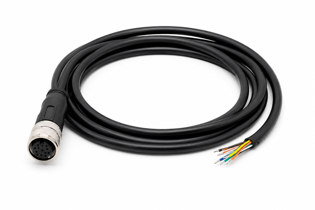
Cable specifications define what the assembly is made from, how it connects, how it behaves electrically, and how it can be manufactured consistently. An RFQ normally needs conductor size, conductor count, cable construction, insulation and jacket requirements, shielding, dimensions, connector identification, pinout, and any overmolding or strain-relief requirements. Generic descriptions such as “heavy-duty cable” or “shielded industrial cable” leave too many variables open for reliable production pricing.
Which Wire and Cable Details Are Needed?
Conductor size is often one of the first specifications discussed because it influences electrical capacity, termination compatibility, cable diameter, flexibility, and material cost. AWG is common in North American specifications, while square millimeters are widely used in metric drawings. For orientation, nominal conductor areas are approximately 0.823 mm² for 18 AWG, 0.519 mm² for 20 AWG, 0.326 mm² for 22 AWG, and 0.205 mm² for 24 AWG, although actual construction and application suitability still need project-specific confirmation.
Conductor size cannot be selected from current alone. Cable length, allowable voltage drop, ambient conditions, conductor stranding, bundling, connector terminal rating, and installation method may all affect the final design. The same nominal gauge can also be built with different strand counts, creating different flexibility and processing behavior. When an engineering specification already exists, the supplier should follow it rather than substituting a preferred conductor construction without approval.
Jacket and insulation descriptions deserve similar care. PVC, TPE, TPU, PUR, silicone, PE, and XLPE can appear in custom cable projects, but the material name by itself does not prove suitability for oil exposure, outdoor use, repeated bending, a specified temperature range, or a particular compliance requirement. The actual grade and supporting documentation should be reviewed when those characteristics are important to the equipment or destination market.
Shielding should be defined beyond a simple yes-or-no field. Foil shielding, braided shielding, and combined structures serve different mechanical and electromagnetic needs. Termination is equally important because the shield may connect to a connector shell, drain wire, chassis point, one end, or both ends according to the system design. Quotation therefore needs enough information to understand both the cable structure and the work required at each termination.
Which Connector Details Must Be Defined?
Connector family names are useful starting points, but they are rarely complete purchasing specifications. A phrase such as “M12 cable,” “circular connector,” “DC plug,” or “D-sub cable” can describe numerous pin counts, genders, keying patterns, orientations, terminal systems, locking mechanisms, and mating configurations. Accurate quoting becomes much easier when an exact manufacturer part number or a sufficiently detailed connector reference is supplied.
The mating connector deserves attention because it can resolve ambiguities that photographs cannot. A cable-side connector may appear visually similar to another version while using different coding or keying. Providing the equipment-side mating part, connector drawing, or clear mating-face photograph gives engineering another way to check compatibility before a sample is produced and physically tested on the target equipment.
Availability can also change the commercial picture. A specified connector may have a supplier MOQ, long purchasing cycle, regional sourcing constraint, or minimum package quantity that is disproportionate to an initial order. If equivalent connectors are permitted, the RFQ should explain whether alternatives may be proposed and what approval is required. If the original brand or exact component is mandatory, that constraint should be equally clear from the beginning.
For custom cable and wire-harness projects, connector confirmation may include model, male or female configuration, pin count, mating part, direction, terminal match, shielding, sealing requirements, overmolding suitability, and availability. These checks are valuable because a connector mistake can leave an otherwise well-manufactured cable impossible to install or test on the actual machine.
How Should Pinout and Polarity Be Specified?
Pinout is one of the few specifications capable of making a cable electrically useless while leaving it visually perfect. For multi-core industrial assemblies, the preferred reference is an explicit pin-to-pin map showing how each contact on one connector relates to the other connector, branch, terminal, or circuit. Wire colors can support identification, but they should not replace controlled circuit information where equipment function depends on exact wiring.
Power assemblies should define polarity whenever reverse connection creates a functional or safety problem. Signal cables may need specific pair assignments, grounding arrangements, drain-wire treatment, or shield termination. Harnesses used inside equipment frequently benefit from wire numbers or circuit identifiers because those markings help assembly, inspection, installation, troubleshooting, and future service teams distinguish circuits that would otherwise look identical.
The RFQ also needs to clarify the viewing convention used in connector diagrams. Pin numbering can be misunderstood if one drawing shows the mating face while another shows the wire-entry side. A simple note defining the connector view can prevent an entire sample from being wired as a mirror image of the intended configuration, especially when photographs or hand-marked sketches are being used instead of a released connector drawing.
Cablivo’s engineering scope includes wire-sequence confirmation and pinout review before sampling and production. The purpose is not to redesign the equipment interface but to reduce mismatch risk by making sure connector direction, circuit mapping, and related termination information are understood before the cable is released for repeatable manufacturing.
Are Overmolding and Strain Relief Details Needed?
Overmolding affects the mechanical design, processing route, tooling requirement, and unit cost of a cable assembly, so it belongs in the RFQ rather than being treated as a cosmetic detail added near the end of development. The required information may include mold shape, connector interface clearance, cable exit direction, color, external dimensions, strain-relief geometry, sealing objective, and any space restriction around the equipment connection.
A custom molded shape can introduce one-time tooling cost in addition to normal piece pricing. Tooling becomes especially important when the overmold must locate the connector precisely, create a controlled exit angle, protect soldered or crimped terminations, or reproduce a customer-specific housing shape. Seemingly small geometry changes can affect mold construction, cavity clearance, cable positioning, material flow, and the ability to remove the finished part without damage.
Strain relief should be linked to the real mechanical load rather than described simply as “strong.” A stationary cable inside a cabinet may need basic connector transition protection, while a sensor cable that repeatedly bends close to the connector may require a different geometry and material approach. The expected bend location, routing, movement, and connector orientation give engineering far more useful information than a generic request for maximum durability.
DFM review can help determine whether cable structure, connector selection, overmolding, labels, and packaging are practical for sampling and repeatable production. Cablivo’s documented engineering capabilities include overmold structure review and tooling discussion, allowing design questions to be identified before the project commits to molds or production materials.
| Specification | Practical RFQ Information | Example Reference Value | Main Quotation Effect |
| Conductor size | AWG or mm² plus application requirement | 18 AWG ≈ 0.823 mm² | Material, terminal and cable diameter |
| Conductor size | AWG or mm² plus application requirement | 20 AWG ≈ 0.519 mm² | Material, flexibility and termination |
| Conductor size | AWG or mm² plus application requirement | 22 AWG ≈ 0.326 mm² | Material and electrical design |
| Conductor size | AWG or mm² plus application requirement | 24 AWG ≈ 0.205 mm² | Material and cable construction |
| Shielding | Foil, braid or defined combined structure | Project-specific | Material and processing |
| Connector | Exact model, gender, pins, mating part | Project-specific | Sourcing and assembly |
| Pinout | Controlled pin-to-pin mapping | Project-specific | Assembly and electrical testing |
| Overmold | Geometry, cable exit, clearance, purpose | Project-specific | Tooling and molding |
| Labeling | Label file, position and numbering logic | Project-specific | Printing, assembly and inspection |
Cable specifications work best when they explain what must be controlled rather than relying on broad adjectives such as premium, rugged, flexible, waterproof, or industrial grade. A manufacturer can price a controlled conductor, connector, shield structure, pinout, tolerance, and molded geometry. It cannot accurately price an undefined performance expectation without first translating that expectation into measurable product requirements.

How Do Application Conditions Affect the Quote?
Application conditions tell the manufacturer what the cable must actually survive after installation. Voltage, current, signal type, movement, moisture, vibration, oil, abrasion, electromagnetic interference, available routing space, and regulatory requirements can all change materials, connector construction, shielding, overmolding, strain relief, and testing. A short but accurate description of the equipment and installation environment can prevent specification errors that would never be visible from a cable photograph alone.
What Electrical Requirements Should Be Provided?
A supplier needs to understand the electrical job of the assembly, not merely the connector shape. For power circuits, useful information can include nominal voltage, operating current, maximum expected current, polarity, grounding arrangement, cable length, and any voltage-drop limit already defined by the equipment design. These details help verify whether the specified conductor, contact system, and insulation approach are consistent with the intended application.
Signal and communication assemblies may require a different set of information. Depending on the equipment, relevant variables can include signal type, frequency range, controlled impedance, differential-pair construction, shielding, grounding, or other electrical characteristics defined by the system. Those requirements should come from the project specification instead of being inferred from the connector, because the same connector family can be used for very different electrical functions.
A useful RFQ also distinguishes confirmed requirements from values that remain under development. If current, impedance, or another parameter is provisional, labeling it clearly allows the quotation to proceed with a defined assumption while keeping the engineering issue visible. Hidden assumptions create trouble later because procurement may compare unit prices without realizing that suppliers interpreted the unfinished electrical specification differently.
Where an existing schematic, interface-control document, or equipment specification already defines the electrical requirement, attaching the controlled reference is often more reliable than rewriting individual values into an email. The objective is consistency: the cable drawing, connector definition, pinout, and electrical requirements should describe one interface rather than a collection of documents produced at different stages of development.
Which Environmental Conditions Matter?
Industrial environments vary too widely for the word “industrial” to function as a useful material specification. One cable may sit motionless inside a temperature-controlled control cabinet, while another runs across automation equipment near vibration, oil mist, moving mechanisms, or exposed connectors. Outdoor installations introduce another set of concerns, including moisture, UV exposure, corrosion, and temperature variation that may not exist inside enclosed machinery.
An RFQ becomes more useful when it describes actual exposure: indoor or outdoor use, humidity, condensation, water splash, wash-down conditions, oil or coolant contact, chemicals, dust, UV, abrasion, vibration, impact, corrosion risk, and nearby sources of electromagnetic interference. Not every project needs a numerical requirement for every condition, but manufacturers should know which environmental factors genuinely influence material or construction choices.
Waterproof-related projects are a good example of why context matters. A sealed connector alone does not automatically create a sealed cable assembly. Connector mating, rear sealing, cable entry, jacket diameter, overmolding, assembly process, and the required validation method may all contribute to the final result. The desired protection level and actual exposure therefore need to be discussed before the quotation assumes a particular connector or molding approach.
Material performance should also be tied to evidence rather than marketing language. If a project requires a specific temperature range, oil resistance, flame behavior, chemical compatibility, or compliance document, the requirement should be supplied so the proposed material can be checked against it. A generic claim that TPU, PUR, PVC, or another material is universally suitable for industrial use is not enough for an engineering decision.
Is the Cable Static or Moving?
Movement changes cable design because repeated flexing creates failure modes that do not exist in a static installation. A cable that is routed once inside an enclosure may experience little motion after installation, while an assembly connected to a moving sensor, robotic mechanism, handheld device, hinged panel, or frequently serviced connector may bend or twist thousands of times during its working life.
Useful RFQ information includes where the cable bends, whether movement is continuous or occasional, the approximate bend radius when controlled by the machine, whether torsion occurs, whether the cable runs through a carrier, and whether connectors are repeatedly plugged and unplugged. These details can influence conductor stranding, shielding construction, jacket choice, overall diameter, strain relief, connector retention, and the validation method chosen for the project.
The word “flexible” alone is not sufficiently precise because flexibility during installation is different from durability under continuous flexing. A soft cable may feel easy to route while still being unsuitable for a repetitive motion pattern. Conversely, a robust static cable may perform well in a fixed machine but fail quickly if the same construction is forced into repeated bending close to a connector transition.
Cablivo’s documented quality capabilities include bending or swing testing and connector insertion/withdrawal life testing for projects where movement or repeated mating needs to be evaluated. The appropriate test conditions still need to come from the application requirement rather than assuming one cycle count or test method fits every industrial cable.
Are Compliance Requirements Needed Before Quoting?
Compliance requirements should be identified while the product configuration is still being quoted because they may affect material selection, component sourcing, documentation, testing, labeling, and the accepted supply chain. Discovering a mandatory requirement after tooling, connector purchasing, or sample approval can force changes that alter both the unit cost and the development schedule.
The most useful approach is to name the requirement that applies to the actual project. A target market may require specific documentation, a corporate specification may control material substances, or the equipment program may require test records from defined components. Procurement should distinguish mandatory requirements from preferences so the manufacturer knows which elements are fixed and where technically acceptable alternatives can still be discussed.
Component-level and finished-product claims also need to remain separate. A connector, jacket compound, or raw material having a particular document does not automatically mean the finished custom cable assembly carries the same certification. Documentation should therefore be reviewed against the actual material source, component, finished construction, intended market, and customer specification rather than copied from a superficially similar product.
Cablivo’s documented content boundary follows the same principle: certification and material-compliance requirements should be confirmed according to the actual product, target market, materials, supplier documentation, and project specification. Universal claims covering all products are intentionally avoided when supporting evidence has not been confirmed for the specific assembly.
| Application Condition | Information to Provide | Possible Design Impact | Quotation Relevance |
| Power load | Voltage, current, polarity, cable length | Conductor, terminals, insulation | Materials and testing |
| Signal transmission | Signal type, shielding, controlled impedance if required | Pairing, shield, connector termination | Cable construction |
| Static installation | Routing and space constraints | Cable OD, connector orientation | Fit and assembly |
| Repeated movement | Bend location, radius, frequency, torsion | Conductor, jacket, strain relief | Material and validation |
| Moisture | Splash, condensation, outdoor exposure | Connector sealing, jacket, overmold | Components and testing |
| Oil or chemicals | Substance and exposure conditions | Material selection | Material sourcing |
| EMI | Motors, drives or interference sources | Foil/braid and termination | Construction and test scope |
| Corrosion | Exposed metal and environment | Terminal and connector review | Component and testing |
| Compliance | Target market or controlled project requirement | Materials, documents and tests | Sourcing and validation |
A cable assembly is ultimately part of a machine or device, so the quotation should reflect the conditions in which the product will operate rather than only the dimensions visible on a drawing. Sharing the real application does not require revealing unnecessary proprietary information. Even a concise description of power, signal, motion, exposure, and installation constraints can give engineering enough context to identify risks before they become sample failures.

What Testing Requirements Are Needed?
Testing requirements should correspond to the cable’s function and the failures that matter in its application. Depending on the project, quotation may need to include continuity, open/short checks, polarity, insulation or Hi-Pot testing, pull-force testing, repeated bending, connector-life testing, dimensional inspection, or environmental evaluation. Not every test belongs on every assembly, so the RFQ should identify the required method, frequency, and acceptance criteria whenever those items affect production.
Which Electrical Tests Are Required?
Continuity testing is one of the most common checks for cable assemblies because it confirms whether intended electrical paths exist. Open/short testing can extend that verification by identifying missing connections or unintended connections between circuits. Polarity checks are particularly important for DC power assemblies, where an apparently simple wiring reversal can prevent the connected equipment from operating correctly or create a more serious electrical problem.
Some projects require insulation-related or Hi-Pot testing according to a defined product or equipment requirement. Others may need resistance, capacitance, impedance, or functional measurements determined by the cable type. The important point is that “electrical testing required” does not fully define the manufacturing task. The manufacturer still needs to understand the test method, limits, test frequency, and whether results must be recorded or only evaluated as pass or fail.
Production frequency can materially affect quotation. A test performed once during engineering validation creates a different workload from a test applied to every finished cable. Likewise, a simple continuity fixture may require far less preparation than a custom fixture connecting several branches and dozens of circuits. Procurement should therefore identify which tests apply during sampling, which apply during routine production, and what records are required for shipment.
Cablivo’s manufacturing and quality resources include cable comprehensive testing and Hi-Pot/insulation testing equipment. Test items are selected according to the actual product and project requirement rather than assuming every cable must receive the same test package. This allows electrical verification to remain tied to the circuit and application risks that the assembly is intended to control.
Which Mechanical Tests Are Required?
Mechanical testing answers questions that electrical testing cannot. A harness can pass continuity and still have a weak terminal crimp. A molded cable can function electrically while the connector transition fails under pulling or repeated bending. A connector can mate correctly during sample inspection but wear prematurely if the application involves frequent insertion and removal.
Pull-force or tensile testing can be useful where termination strength is important, particularly around crimped terminals, cable-to-connector transitions, or overmolded structures. Bending or swing tests address repeated movement, while connector insertion and withdrawal testing focuses on mating durability. None of these tests is a substitute for the others because each reproduces a different potential failure mode.
Acceptance conditions should come from the engineering requirement whenever possible. A request such as “perform pull test” remains incomplete if it does not define which component is being tested, the load or acceptance value, and whether the test applies to samples or production. The same is true for repeated bending: cycle count, bend radius, load, orientation, and post-test electrical criteria can significantly change what the test actually demonstrates.
Cablivo’s documented equipment base includes tensile-testing capability, multi-station cable swing testing, and connector insertion/withdrawal life testing. Those capabilities support project-specific validation discussions, while test limits and conditions remain dependent on the cable design and customer requirement rather than being presented as universal performance values.
Are Environmental Tests Necessary?
Environmental testing is useful when temperature, humidity, corrosion, or another exposure represents a meaningful product risk. Temperature and humidity chambers can help evaluate assemblies intended for changing environmental conditions, while salt-spray testing may be relevant to exposed terminals, connector metalwork, or other components where corrosion performance matters. The test only adds value, however, when it reflects a real application requirement.
Adding every available reliability test to an RFQ may appear thorough, but it can increase development time and cost without improving the final product. A stationary harness inside a protected cabinet may not need the same environmental program as an outdoor connector assembly. A moving sensor cable may gain more useful evidence from bending evaluation than from a corrosion test that has little relationship to its installation.
The better approach begins with failure modes. If moisture could reach a connector, sealing and environmental evaluation deserve attention. If exposed metal will operate in a corrosive atmosphere, corrosion resistance becomes relevant. If a cable experiences repeated temperature changes, material and assembly behavior under those conditions may need to be reviewed. Testing then becomes a response to risk rather than a checklist copied from an unrelated product.
Cablivo’s documented reliability resources include salt-spray equipment and high/low-temperature constant-temperature/humidity chambers. These resources can support industrial cable projects where environmental evaluation is appropriate, while actual exposure conditions, duration, acceptance criteria, and applicable standards must still be defined according to the project.
How Should Acceptance Criteria Be Defined?
A test requirement has limited value if manufacturing and quality teams do not know what constitutes a pass. Acceptance criteria turn general expectations into repeatable decisions. Electrical continuity can be checked against an approved pinout, dimensions against the released drawing, polarity against the circuit definition, label position against controlled artwork, and molded appearance against defined criteria or an approved production reference.
Sample approval is especially useful when it establishes a physical reference for characteristics that are difficult to communicate with numbers alone. Connector fit, cable handling, molded appearance, label position, routing, and packaging presentation may all benefit from a reviewed sample. The approved sample should not replace drawings or BOMs where measurable specifications exist, but it can complement them and help reduce interpretation differences before volume production.
Once a sample is approved, the production baseline should include the final drawing, BOM, connector information, materials, labels, packaging files, and relevant testing requirements. Changes after approval should be controlled rather than allowed to occur informally because even an apparently harmless material or connector substitution can create sample-to-production differences that affect fit, function, appearance, or downstream customer approval.
Cablivo’s quality-control framework covers incoming material inspection, in-process inspection, finished-product inspection, reliability testing, packaging inspection, and pre-shipment review according to product type and project requirements. The purpose is to connect specification control with production checks rather than treating final inspection as the only point where quality is considered.
| Test | Primary Question | RFQ Information Needed | Acceptance Basis |
| Continuity | Are intended circuits connected? | Approved pinout | Correct circuit path |
| Open/short | Are unwanted connections present? | Circuit definition | No unintended connection |
| Polarity | Is power wiring correct? | Positive/negative definition | Correct polarity |
| Hi-Pot / insulation | Does insulation meet the project requirement? | Test method and limits | Defined project criteria |
| Pull force | Is the termination mechanically secure? | Component and required force | Specified threshold |
| Bending / swing | Can the cable tolerate defined repeated motion? | Bend condition and cycles | Post-test project criteria |
| Connector life | Can mating survive the required cycles? | Connector and cycle requirement | Defined mating criteria |
| Temperature / humidity | How does the assembly respond to exposure? | Conditions and duration | Project specification |
| Salt spray | Is corrosion performance relevant and acceptable? | Exposure conditions and parts | Project specification |
| Dimensional inspection | Will the assembly fit? | Drawing and tolerances | Released drawing |
Testing is most persuasive when each test can be traced to a practical failure that the project needs to prevent. That approach also creates a better quotation because test fixtures, test time, inspection frequency, data-recording requirements, and acceptance limits become visible before production. A long test list without defined conditions can look impressive while giving engineering and procurement very little useful evidence.

How Do Quantity and Delivery Affect Pricing?
Quantity and delivery information influences connector purchasing, material preparation, tooling allocation, production setup, testing, packaging, and shipment planning. A practical RFQ should identify the quantity being quoted, quantity per SKU, initial production volume, likely repeat demand where available, packaging method, shipping destination, and required project timing. Lead time can then be evaluated against the actual cable structure, component availability, tooling, testing, and order conditions.
What Quantities Should Be Included?
“Mass production quantity” is too vague for a useful commercial comparison because manufacturing cost changes with the number of assemblies, the number of SKUs, component purchasing conditions, and the amount of setup required. Procurement should give suppliers a defined quantity for the current quotation and, where useful, additional quantity breaks that reflect realistic purchasing scenarios rather than arbitrary numbers chosen only to search for a lower unit price.
Prototype, pilot, and production quantities should also be kept distinct. A small sample run may involve manual preparation, engineering review, temporary fixtures, or material purchasing that is inefficient at low volume. A production order can distribute some preparation work across more pieces, while a long-term supply program may justify different purchasing arrangements. These are legitimate manufacturing differences rather than simply volume discounts applied to an unchanged process.
SKU mix can be just as important as total volume. An order containing four cable versions with different lengths, connectors, labels, or packaging is not operationally identical to one product ordered at the combined quantity. Each SKU may require separate material control, work instructions, test programs, label verification, packaging, and carton identification, especially when several versions look similar on the production floor.
For many Cablivo custom cable projects, MOQ starts from 500 pieces, with the final MOQ depending on connector type, cable structure, materials, overmolding, tooling, packaging, and order quantity. The figure should therefore be understood as a starting commercial reference rather than a universal requirement applied identically to every product configuration.
How Do Materials and Tooling Affect the Quote?
Cable assembly cost includes more than conductor and jacket material. Connectors, terminals, seals, shielding materials, sleeves, molded components, labels, packaging, and other accessories can account for a substantial part of the project cost. Some components are standard and easy to source, while others involve supplier MOQs, extended procurement cycles, approved-source restrictions, or order quantities that do not align neatly with the requested cable quantity.
Tooling creates another commercial layer because it may be a one-time development cost rather than part of the recurring unit price. Custom overmolds can require dedicated molds, specialized assembly layouts can need fixtures, and complex electrical assemblies may benefit from dedicated test fixtures. Quotations are easier to compare when these charges are shown separately from recurring material and assembly cost instead of being hidden inside the piece price.
Approved substitutions also need to be understood. If the specified connector or material is mandatory, that constraint should remain visible to every supplier. If an equivalent may be proposed, the approval process should be defined. Otherwise, two manufacturers may quote products that look similar in a spreadsheet but use different sourcing assumptions, component brands, materials, or tooling approaches that make the unit prices impossible to compare fairly.
DFM review can expose those issues before quotation turns into a purchase decision. Cablivo’s documented engineering review includes connector sourcing, terminal suitability, cable structure, overmolding, tooling, material selection, labeling, packaging, and testing considerations, allowing commercially significant risks to be identified before sample and production specifications are locked.
Do Packaging and Labeling Requirements Matter?
Packaging belongs in the RFQ because it is part of the delivered product. A factory may assume bulk packing while the actual order requires individually coiled cables, protective connector caps, PE bags, wire-number labels, customer SKU labels, barcode labels, fixed carton quantities, and customer-specific carton marks. Those additions change material consumption, labor, inspection, shipping volume, and production documentation.
Multi-SKU industrial orders make labeling especially important. Two assemblies can have similar connectors and cable colors while serving different equipment variants or different branch lengths. If the warehouse or installation team cannot distinguish them quickly, the manufacturing work may be technically correct while the shipment still causes receiving, kitting, or installation problems. Clear SKU and cable identification helps control that downstream risk.
Private-label or channel-specific packaging introduces another set of dependencies. Artwork, barcode files, carton marks, retail boxes, or customer labels need final approved files before production. Late artwork changes can delay packaging even when the cable assemblies themselves are complete. RFQs should therefore indicate whether final files already exist and, if not, what temporary packaging assumption should be used for the initial quotation.
Cablivo’s documented packaging scope includes bulk packing, bags, industrial packing, export cartons, private-label packaging, product labels, wire-number labels, barcode labels, customer SKU labels, batch labels, and carton marks according to project requirements. Packaging and label details are confirmed before mass production to reduce SKU and shipment confusion.
What Delivery Information Is Needed?
A requested date gives the manufacturer a target, but it does not automatically create a confirmed production lead time. Before a schedule can be evaluated, the project may need connector sourcing, cable or material preparation, tooling, sample approval, test fixture development, production scheduling, packaging-file confirmation, and export preparation. Different cable structures can therefore have very different timelines even when the required quantity is the same.
Useful RFQ timing information includes the desired sample timing, equipment validation date, pilot build, required production delivery window, installation or maintenance deadline, shipping destination, preferred shipping mode, and whether partial shipments are acceptable. Those details help identify which dates are genuinely critical and whether the project needs one complete shipment or can be planned around staged manufacturing and delivery.
Shipping destination is also relevant before the finished cables reach the logistics stage. Packaging size, export carton configuration, documentation, freight mode, customer-appointed forwarder arrangements, and warehouse requirements may all influence the final delivery plan. Commercial invoice, packing list, carton information, and shipping marks can be prepared according to order details, while destination-country customs requirements still need confirmation with the relevant forwarder or customs professional.
Cablivo’s documented scheduling boundary avoids universal promises for sample or production time. Lead time depends on product structure, material availability, connector sourcing, tooling, quantity, testing requirements, and packaging plan, with production scheduling confirmed after the approved sample and final order information are available.
| Commercial Input | Practical RFQ Example | Main Cost or Schedule Effect | Confirmation Point |
| Quote quantity | 500 / 1,000 / 5,000 pcs | Material purchasing and setup allocation | Quantity per SKU |
| SKU mix | Multiple lengths or connector versions | Separate material, labels and inspection | SKU-level quantities |
| Connector source | Exact specified model or approved alternative | Price, MOQ and procurement time | Approved sourcing route |
| Custom tooling | Overmold or dedicated fixture | One-time development cost | Tooling specification |
| Test frequency | Validation only or production testing | Fixture and test time | Test plan |
| Packaging | Bulk, individual bag, private label | Materials and labor | Approved packaging files |
| Labeling | SKU, barcode, wire number, carton mark | Printing and inspection | Final label files |
| Destination | Country, warehouse or forwarder | Packing and logistics planning | Shipping arrangement |
| Required timing | Pilot, launch or installation date | Material and production priority | Feasible schedule |
| Repeat demand | Forecast or planned reorder range | Purchasing and production planning | Forecast review |
The most reliable price comparison happens when every supplier receives the same commercial and technical baseline. Drawing revision, BOM, connector model, material, pinout, quantity, test scope, packaging, tooling assumptions, and delivery requirement should all match. A lower quotation is not necessarily less expensive if tooling, testing, labels, packaging, or a required connector has simply been left outside the quoted scope.
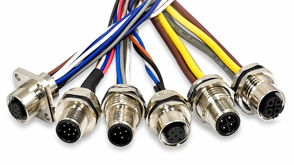
An accurate industrial cable assembly RFQ does not need to begin with a perfect stack of engineering files. It needs enough reliable information to make the remaining uncertainties visible. A drawing, sample, BOM, connector reference, cable specification, pinout, application description, quantity, testing requirement, and packaging plan together allow engineering and procurement to discuss the real product rather than a price based on assumptions.
For projects that are still incomplete, the useful next step is usually not to guess the missing specification. Photos, an existing sample, connector details, application information, or partial drawings can be reviewed first, after which the remaining requirements can be identified for confirmation. That creates a much safer route from initial quotation to sample approval and from an approved sample to repeatable production.
Cablivo supports custom cable, wire-harness, and cable-assembly projects through requirement review, drawing and BOM review, connector and pinout confirmation, material discussion, sample development, production preparation, project-based testing, packaging, labeling, and shipment coordination. The company’s documented project process is designed around reducing specification ambiguity rather than treating the first incomplete RFQ as a finished production definition.
For an industrial cable assembly quotation, send the information already available: drawing, sample photos, BOM, connector model, cable length, wire gauge, pinout, wire sequence, application environment, target quantity, testing requirements, packaging requirements, and shipping destination. The available files can be reviewed first, and any specifications that still need confirmation can be identified before sampling or production planning begins.



