 Skip to content


A DB9 cable often looks simple from the outside: two connectors, one length of cable, and perhaps a pair of thumbscrews. Inside, however, two assemblies with the same appearance may use different pin assignments, conductor counts, shielding methods, cable materials, backshells, and test plans. One may be a straight-through serial cable, another may cross transmit and receive signals, and a third may carry proprietary control lines or low-voltage power. Quoting all three from the phrase “two-meter DB9 cable” would force the manufacturer to guess. A useful quotation begins when the product is described as a complete electrical and mechanical assembly rather than as a connector name. The more clearly the application, interfaces, construction, quantities, and acceptance criteria are defined, the easier it becomes to compare quotations, approve a sample, and move into repeatable production without discovering hidden assumptions later.
An accurate DB9 cable assembly quote requires the connector gender and part numbers, complete pin-to-pin wiring, equipment application, cable length, conductor structure, shielding, backshell, locking hardware, operating environment, test requirements, order quantity, packaging, and delivery expectations. A drawing, wiring table, BOM, equipment manual, or physical sample helps verify these details and exposes unresolved decisions before final pricing.
The most expensive problems often begin with a very short request. A supplier assumes straight-through wiring, but the equipment needs a crossover arrangement. The sample arrives, both connectors fit, the workmanship looks clean, and nothing communicates. That result is not always a manufacturing defect; it may be the predictable outcome of an undefined pinout. The sections below show how engineering and procurement teams can replace guesswork with a quotation package that is practical for sampling, quality control, and production planning.
What Basic Project Information Is Required?
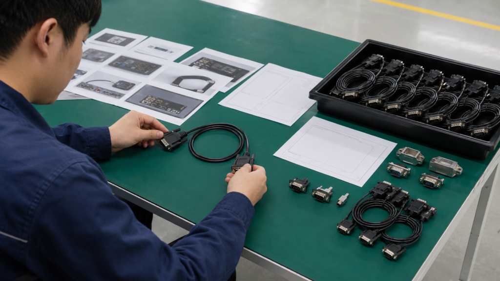
An accurate DB9 cable assembly quote starts with the cable function, the two connected devices, the project type, the available reference files, the quantity by project stage, and the required schedule. These details establish the real scope before the manufacturer evaluates connectors, materials, tooling, testing, packaging, and production planning. Clear project context also prevents a standard serial construction from being assumed for a proprietary equipment cable.
Application and Equipment
Start with the job the cable must perform, not merely the connector visible at each end. DB9 assemblies appear in PLCs, CNC machines, laboratory instruments, weighing systems, test equipment, POS terminals, security systems, and legacy computers. The same nine-position shell can carry RS-232 communication, RS-422 or RS-485 signals, machine-control circuits, alarm contacts, or a proprietary combination of signal and low-voltage power. A short application statement should identify the equipment, the connection purpose, and the operating location. For example, a cable connecting a computer serial port to a weighing controller inside a metal cabinet near a variable-frequency drive gives the engineering team useful clues about shielding, cable routing, strain relief, and possible interference.
Identify both connected devices whenever the information is available. Include the equipment manufacturer, model number, port description, mating connector, and the relevant page from the equipment manual. Clear photographs of both ports are valuable when the device is old, modified, or no longer supported. They can reveal connector gender, panel depth, screw hardware, and available cable-exit space. Application photos also help expose practical issues that a line drawing may miss, such as a cabinet door that limits backshell length or a tight bend immediately behind the connector.
New Design or Replacement
A new product design and a replacement-cable project need different evidence. For a new design, provide the proposed electrical interface, signal list, mechanical envelope, operating conditions, and expected production volume. The manufacturer can then review whether the connector, wire gauge, cable diameter, shield, and strain-relief concept are compatible. When the design is still open, mark preferred features separately from fixed requirements so that alternative materials or connector constructions can be evaluated without creating confusion about what has already been approved.
For a replacement project, the existing cable may be the strongest reference. Send photographs of both connectors, cable markings, labels, locking screws, backshells, and any damaged areas. Include the original part number and equipment model, and state whether the goal is an exact reproduction or an improvement. If failures repeatedly occur near the connector, the project may need better strain relief rather than a simple copy. When only one working sample exists, agree in advance whether it must remain intact, because reverse engineering may involve continuity testing, dimensional inspection, or controlled disassembly.
Reference Files
A formal drawing is ideal, but a project can begin with a wiring table, BOM, connector datasheet, equipment manual, hand sketch, sample photographs, or a physical cable. The strongest RFQ package combines electrical and mechanical references: the pinout defines function, while dimensions and photographs define fit. Each file should carry a date or revision so that engineering, purchasing, sample development, and production teams do not work from different versions. A simple revision mismatch can produce a cable that is built correctly to the wrong document.
Separate confirmed requirements from open decisions. Write “DB9 female required” when gender is fixed, and write “PVC or TPE to be evaluated” when the jacket is still under review. This distinction allows the supplier to state assumptions honestly and prevents a preliminary option from being treated as an approved specification. If the pinout, connector model, or shielding method is still unknown, the quotation should be described as budgetary until those points are verified.
Quantity and Timing
Quantity should be separated into engineering samples, pilot production, the first firm order, and expected repeat demand. A five-piece sample build may require small-lot connector purchasing, manual setup, extra inspection, and direct engineering involvement. Production pricing may change when cable reels, connector package quantities, printed labels, or carton quantities can be purchased more efficiently. A realistic annual range is more useful than an inflated forecast because it allows the quotation to reflect purchasing conditions that can actually be reached.
State the required sample date and production target, but recognize that timing begins after key inputs are confirmed. Connector availability, custom cable preparation, tooling, test requirements, packaging artwork, and sample revisions can all affect the schedule. A practical RFQ therefore identifies the business target while allowing the manufacturer to confirm a workable plan after reviewing the final drawing, BOM, pinout, quantity, and packaging files.
| Project input | Minimum detail to provide | Selection or review value | Risk when missing |
| Cable function | Signal, control, data, power, or mixed use | Defines the electrical and material scope | An unsuitable standard construction may be assumed |
| Connected equipment | Two device models, mating ports, and port photos | Confirms interface, gender, hardware, and clearance | The cable may not mate or fit the installation |
| Project type | New design, exact replacement, or redesign | Clarifies engineering and validation work | Important redesign expectations may be overlooked |
| Technical references | Drawing, pinout, BOM, manual, photos, or sample | Reduces hidden assumptions and revision conflict | Repeated quotation and sample changes |
| Quantity stages | Sample, pilot, first order, and annual estimate | Supports material purchasing and setup planning | Unit pricing may be unrealistic |
| Required dates | Sample target and production target | Allows sourcing and tooling review | Schedule expectations may not match the real scope |

Which DB9 and Pinout Details Matter?
A production-ready quote must define the DB9 connector mechanically and electrically. Required details include the gender of each end, the exact pin-to-pin map, active and unused contacts, signal names, straight-through or crossover wiring, shield termination, backshell style, cable-exit direction, and locking hardware. The nine-position shell identifies a connector family, but it does not confirm protocol, wiring, grounding, or equipment compatibility.
Connector Gender and Mating
State the gender of each cable-end connector in plain language and support it with a drawing or photograph. Common combinations include male-to-male, male-to-female, female-to-female, and DB9-to-another interface. Errors occur when a request describes the equipment port rather than the cable connector needed to mate with it. If the machine has a male port, the cable normally needs a female connector. A port photograph can also reveal panel hardware, recess depth, and whether a bulky hood will interfere with nearby components.
Provide the exact connector part number when a specific component has already been approved. If an equivalent is acceptable, define the characteristics that cannot change, such as termination style, shell dimensions, contact finish, mounting hardware, cable-entry range, or approved source. The mating hardware requires the same attention. Commonly encountered threads include 4-40 and M3, but the equipment must be checked rather than assumed. A connector that mates electrically but cannot be secured is not an acceptable replacement.
Protocol and Signal Use
DB9 is strongly associated with serial communication, but the connector is not limited to one protocol or one signal assignment. It may be used for RS-232, RS-422, RS-485, machine controls, alarm contacts, test signals, or proprietary power-and-signal combinations. The RFQ should identify the interface and name every active signal. For RS-232, this may include TXD, RXD, signal ground, and any required handshake lines. For differential interfaces, identify each pair and its polarity according to the equipment documentation.
The application can also change the cable construction. A short, fixed service cable between nearby instruments may require a simpler structure than a long cable routed beside drives, motors, or switching equipment. When the protocol is proprietary, do not use a phrase such as “standard DB9 wiring.” Supply the equipment manual or a controlled pin table, because a familiar connector shape does not make an unfamiliar circuit safe to infer.
Straight-Through or Crossover
A straight-through assembly normally connects matching positions from one end to the other, while a crossover or null-modem arrangement changes selected connections so two devices can communicate correctly. The phrase “null modem” is not a complete specification. Some versions cross only transmit and receive, while others also cross handshake lines or add jumpers inside one connector. A controlled wiring table is therefore safer than a product name, especially when the cable supports older equipment with undocumented variations.
The table should show Connector A pin, signal name, wire color, Connector B pin, internal jumpers, shield connection, and all unused positions. Mark unused pins as “NC” rather than leaving blank cells that could be read as missing information. When an existing cable is available, a continuity test can establish the electrical map, but it will not reveal conductor gauge, shield coverage, contact material, or the design reason behind internal bridges. The measured map should be reviewed together with the application and equipment documentation.
Backshell and Hardware
Backshell selection affects installation, shielding, cable retention, serviceability, and long-term durability. Options may include molded plastic, metalized plastic, die-cast metal, assembled hoods, or custom overmolded structures. A metal hood can support mechanical protection and shell continuity, while an assembled plastic hood may be sufficient for a stationary, low-risk installation. A molded design can improve strain relief, appearance, and repeatability after the geometry has been validated through samples.
Confirm the maximum cable diameter, cable-exit direction, permitted envelope, and screw hardware. Straight, top-entry, side-entry, or angled exits can make the difference between a clean installation and a connector that collides with a cabinet wall. The finished cable must fit the hood entry without crushing the shield or creating an abrupt bend. Locking screws should be specified by thread, length, and captive or removable design. These small mechanical details often decide whether the cable can be installed, secured, and serviced correctly.
| DB9 detail | Common options | Decision basis | Risk of a wrong choice |
| Connector gender | Male or female at each end | Mating equipment port | The assembly cannot connect |
| Pin use | 3, 5, 9, or a custom selection of contacts | Required signals and controls | Functions may be missing or wrongly connected |
| Wiring pattern | Straight-through, crossover, or proprietary | Equipment signal assignment | Communication or control failure |
| Protocol | RS-232, RS-422, RS-485, or custom | Device manual and system design | Incorrect conductor or grounding arrangement |
| Shield termination | Shell, pin, one end, both ends, or isolated | System grounding and EMI plan | Noise, ground-loop, or shielding problems |
| Backshell | Plastic, metalized, metal, or overmolded | Environment, serviceability, and cable diameter | Poor fit or inadequate protection |
| Locking hardware | Common examples include 4-40 and M3 | Equipment panel thread and depth | The connector cannot be secured |
| Cable exit | Straight, top, side, or angled | Panel clearance and routing | Mechanical interference or excessive bending |

How Should the Cable Construction Be Specified?
The cable specification should define finished length, tolerance, conductor count, wire gauge, conductor material, insulation, shielding, outer jacket, cable diameter, flexibility, color, strain relief, overmolding, and identification. These choices affect electrical performance, installation fit, material cost, and manufacturing method. When the exact material is undecided, describe the operating environment and approval criteria so suitable constructions can be compared before sampling.
Length and Tolerance
Define exactly where the finished length begins and ends. One company may measure from connector face to connector face, while another measures between backshell exits or overmold ends. A dimension line on the drawing removes that ambiguity. Include the nominal length, tolerance, exposed-wire lengths, branch dimensions, strip lengths, and any required service loop. For a two-meter assembly, a tolerance such as plus or minus 20 to 50 mm may be a workable commercial example, but fixed machine routing may require a different project-specific limit.
Tighter tolerances should be reserved for dimensions that affect installation, mating, sealing, or moving equipment. Applying an unnecessarily strict limit to every dimension adds cutting and inspection work without necessarily improving performance. For replacement cables, measure the reference in a relaxed condition and note any permanent bends or coiled sections. If the cable route is fixed, provide the routing distance and connector orientation so that the finished assembly does not pull on the equipment or leave excessive slack inside the enclosure.
Conductors and Wire Gauge
Wire gauge should be selected from current, voltage drop, cable length, flexibility, connector termination range, and available backshell space. Low-current signal circuits often begin in the 24 to 28 AWG range, while mixed power-and-signal assemblies may need larger conductors such as 20 to 24 AWG for the power paths. These are discussion ranges rather than universal defaults. The actual design must be checked against the equipment load, contact capacity, insulation, temperature conditions, and the connector’s solder-cup or crimp-contact limits.
Specify conductor count, AWG or square-millimeter size, stranded or solid construction, bare or tinned copper, insulation colors, and any twisted pairs. Larger conductors are not automatically safer. They increase cable diameter, reduce flexibility, and may be difficult to terminate in a compact DB9 backshell. When the required gauge is unknown, provide voltage, maximum continuous and peak current, total length, movement conditions, and allowable voltage drop. That information gives the engineering team a defensible basis for comparing constructions.
Shielding and Jacket
Shielding should answer a real interference risk. Common constructions include overall foil, overall braid, combined foil and braid, individually shielded pairs, or no shield. Foil can provide high coverage in a compact structure, while braid adds mechanical robustness and can support effective low-frequency shielding. Combined constructions may be useful in demanding environments but increase cable diameter, weight, material cost, and termination labor. Shield performance also depends on how the braid, foil, drain wire, and connector shells are terminated.
Select the jacket from flexibility, abrasion, temperature, oil or chemical exposure, appearance, target market, and cable-routing needs. PVC, TPE, TPU, PUR, silicone, and PE are possible material directions, but the actual compound and supporting documents must be reviewed. A material name alone does not guarantee a specific temperature rating, flame classification, or compliance status. Describe the environment first, then confirm the final material, color, diameter, and required documentation before approving the sample and production BOM.
Overmolding and Identification
Overmolding can provide repeatable strain relief, connector protection, tamper resistance, branding, and a controlled cable-exit shape. The RFQ should define the maximum envelope, overmold dimensions, exit direction, bend-relief length, surface texture, color, logo, and any sealing objective. Tooling may be required when the project needs a unique shape, restricted size, special logo, or unusual cable transition. Existing molds can sometimes be considered, but compatibility with the connector, cable diameter, and required appearance must be checked.
An assembled metal or plastic backshell may be more practical for a low-volume service cable, while a molded structure may provide better repeatability for a long-term program. Identification should be planned at the same stage. Cable printing, heat-shrink markers, part-number labels, revision codes, serial numbers, and orientation labels can reduce installation and inventory errors. When both ends look similar, simple labels such as “Controller End” and “Equipment End” may prevent a field failure that no electrical test would detect before installation.
| Construction item | Useful starting specification | Main review factor | Selection value |
| Finished length | Named reference points plus a stated tolerance | Equipment routing and service loop | Prevents tension, slack, and fit problems |
| Signal conductors | Common discussion range: 24-28 AWG | Signal level, termination, and flexibility | Controls diameter and handling |
| Power conductors | Possible discussion range: 20-24 AWG | Current, voltage drop, and contact capacity | Supports safe mixed power-and-signal designs |
| Conductor material | Bare or tinned copper | Environment, soldering, and supplier documents | Supports process and corrosion requirements |
| Shielding | Foil, braid, combined, individual, or none | EMI source, cable length, and grounding | Avoids both under-design and unnecessary cost |
| Jacket | PVC, TPE, TPU, PUR, silicone, or PE options | Flexibility, abrasion, chemicals, and market needs | Matches real use rather than a generic label |
| Cable diameter | Must fit the selected backshell entry | Conductor count and shield structure | Prevents mechanical incompatibility |
| Strain relief | Standard boot, assembled clamp, or custom overmold | Movement, pull exposure, and program volume | Reduces stress at the connector transition |
| Identification | Print, heat shrink, label, barcode, or serial number | Installation and traceability | Reduces SKU and connection errors |

What Application and Tests Affect the Quote?
Application conditions determine which tests reduce real project risk and which tests add cost without useful evidence. The RFQ should describe voltage, current, signal type, movement, vibration, temperature, moisture, interference, and documentation needs. Basic custom DB9 checks commonly cover pinout, continuity, unintended shorts, connector fit, and appearance. Additional electrical, mechanical, or environmental tests require agreed methods, limits, frequency, and reporting.
Operating Environment
A DB9 assembly inside a clean laboratory experiences different risks from one installed on a production floor. Describe whether the cable is indoors or outdoors, fixed or moving, frequently disconnected or permanently installed, and exposed to vibration, pulling, humidity, dust, oil, chemicals, or changing temperature. Nearby motors, drives, relays, and switching power supplies should also be mentioned because they may influence shielding, grounding, and cable routing. The goal is not to select the most expensive construction, but to match protection to the actual environment.
Mechanical clearance deserves the same attention. A thick shielded cable and long metal hood may be electrically suitable but impossible to fit behind a panel. Photographs of the installation can reveal the available bend space, connector access, and cable-exit direction. Explain how technicians handle the cable during maintenance. A cable that is regularly pulled by the jacket needs stronger strain relief than one that remains untouched inside a cabinet. Real handling information often provides more value than a broad request for an “industrial-grade” product.
Electrical Requirements
Provide the operating voltage, maximum continuous current, peak current when relevant, signal type, protocol, and each power or return pin. A standard serial cable may be defined mainly by its signal map, while a proprietary DB9 assembly carrying power and data requires conductor sizing, polarity review, insulation decisions, and additional test planning. The manufacturer should not be expected to establish safe electrical ratings from a connector photograph. System engineers need to supply or approve the operating conditions.
For signal applications, include the communication interface, cable length, data rate when known, grounding plan, and expected interference sources. State whether the shield is intended for chassis bonding, signal protection, or another purpose. Connecting the shield at both ends can be appropriate in one system and problematic in another, so the final termination should follow the equipment design rather than a workshop habit. A clear electrical specification also helps separate cable-related communication problems from incorrect device settings during functional validation.
Functional and Electrical Tests
The first essential check is comparison with the approved pinout. A cable tester can verify required continuity, unused-pin isolation, and the absence of unintended shorts. This is especially important for crossover wiring, internal jumpers, mixed power and signal, or identical connectors at both ends. For custom wiring, 100 percent continuity and pin-sequence testing is a common production approach when specified, while qualification tests and detailed measurements may use an agreed sampling plan. The quotation should state which checks apply to every unit.
Additional tests can include polarity, shell continuity, insulation resistance, Hi-Pot, resistance measurement, and functional communication. A continuity test proves that the cable matches the wiring table, but it does not always prove that two devices will communicate if protocol settings or equipment configuration are wrong. Functional testing is strongest when the final equipment, a representative fixture, or a controlled procedure is available. Acceptance limits, test voltage, duration, reporting, and fixture responsibility should be agreed before the price is finalized.
Mechanical and Documentation Checks
Mechanical tests should reflect real handling. A pull-force test may be useful for crimped contacts, soldered conductors, exposed wire ends, or overmolded transitions, but the force, direction, hold time, sample quantity, and failure definition must be stated. A flex or swing test needs the bend angle, load, cycle count, speed, and pass criteria. Without those conditions, two suppliers may perform very different procedures while using the same test name, making the results difficult to compare.
Inspection records, first-article reports, material declarations, certificates of conformity, and shipment test summaries should be identified at the RFQ stage. Documentation adds traceability and review work, so it should not appear as an afterthought. Clarify whether records are needed only for the first production lot, for periodic validation, or with every shipment. Environmental evaluations such as temperature and humidity, salt spray, or material flammability should be included only when the application and specification justify them, with parameters confirmed before testing.
| Test or review | What it verifies | Information to define | Common use |
| Pinout check | Correct pin-to-pin assignment | Approved wiring table and revision | All custom DB9 assemblies |
| Continuity and shorts | Required circuits connect and unintended circuits remain isolated | Active pins and isolation rule | Often specified for every production unit |
| Polarity check | Power and return are correctly assigned | Voltage and pin designation | Mixed power-and-signal cables |
| Connector-fit check | Mating, screw hardware, and clearance | Mating part or equipment port | Replacement and industrial assemblies |
| Shell continuity | Shield path and shell connection | Grounding and termination requirement | Shielded cable systems |
| Hi-Pot or insulation | Electrical isolation | Test voltage, time, and leakage limit | Projects with defined safety requirements |
| Pull-force test | Termination and strain-relief strength | Force, direction, duration, and sample plan | Crimped, soldered, or overmolded joints |
| Flex or swing test | Durability under repeated bending | Angle, load, cycles, speed, and failure rule | Moving service cables |
| Functional test | Communication or equipment operation | Device, fixture, protocol, and procedure | Critical serial or proprietary links |
| Label and packing check | SKU, revision, quantity, and shipment accuracy | Approved artwork and packing file | Multi-SKU and export orders |

How Do Commercial Details Finalize the Quote?
Commercial details turn an engineering estimate into an order-ready quotation. The manufacturer needs sample and production quantities, realistic repeat demand, tooling responsibility, packaging, labels, documentation, delivery destination, and requested timing. The quotation should separate recurring unit price from molds, fixtures, engineering, special testing, and other one-time charges. It should also identify remaining assumptions and whether the price is budgetary or based on an approved specification.
Volume and Price Breaks
Request prices at quantities that match the real program: engineering samples, a pilot build, the first production order, and a realistic repeat range. Sample pricing includes small-lot materials, setup, engineering review, and additional inspection, so it should not be compared directly with a production unit price. Higher quantities may improve pricing when connectors can be purchased in full packages, cable in full reels, labels in standard print runs, or cartons in efficient packing quantities. The quotation should explain the breakpoints that materially change cost.
Avoid using an annual forecast that is unlikely to become an order. A range such as an initial 1,000 units and an estimated 5,000 to 10,000 units per year gives the supplier a practical basis for discussion without pretending that future demand is fixed. For many custom cable projects, the manufacturer’s documented MOQ begins from 500 pieces, while the final level depends on connector type, cable structure, materials, overmolding, tooling, packaging, and the number of variants. Each DB9 project still needs individual review.
Tooling and One-Time Costs
One-time charges may include a custom overmold, mold insert, assembly fixture, soldering fixture, pinout test fixture, inspection gauge, logo setup, packaging artwork, engineering work, or external testing. These items should be separated from the recurring unit price so that purchasing teams can compare quotations on the same basis. The quote should explain what each tool does, whether it is dedicated to the project, who owns it, how it is stored, and how future revisions or maintenance are handled.
A low-volume service cable may be better served by an assembled hood that avoids tooling, while a long-term branded program may justify a dedicated molded structure for appearance, strain relief, and repeatability. Small geometry changes do not always have small tooling consequences. A logo insert might be replaced independently, whereas a different cable-exit direction or connector envelope may require major rework. Tooling decisions should therefore be linked to expected volume, product life, revision risk, and the value of a stable production process.
Packaging and Documentation
Packaging should reflect how the cable will be stored, installed, shipped, or sold. Options may include bulk coils, individual bags, cable ties, connector caps, foam protection, inner boxes, retail boxes, export cartons, or installation kits. Industrial projects sometimes need matched pairs or sequence-controlled packing, while distributors may require barcodes, SKU labels, printed cards, and multiple versions in one shipment. A packing matrix can show part number, label, bag quantity, inner-carton quantity, master-carton quantity, and carton mark for each version.
Provide approved files for product labels, cable printing, barcodes, warning labels, carton marks, and packing instructions. First-article reports, inspection records, material declarations, certificates of conformity, and shipment summaries should be identified before quotation because they require review and traceability work. Packaging protection deserves special attention for DB9 connectors because exposed pins, screws, and backshells can be damaged or scratch neighboring products during transport. The final plan should protect the product while remaining practical for the customer’s warehouse and installation process.
Lead Time and Quote Status
Separate sample timing from production timing. Sample development may include specification review, connector sourcing, custom cable preparation, tooling, assembly, testing, customer evaluation, and revision. Production scheduling normally begins after the sample, drawing, BOM, labels, packaging, and order details are approved. Connector availability and custom tooling can be more important than assembly time, so a promised date issued before technical review may create false confidence rather than useful planning.
The quotation should identify whether it is budgetary, based on photographs, based on an unverified sample, ready for prototype ordering, or based on a complete approved specification. It should list open assumptions and specify a validity period; 15 to 30 days is a common commercial reference, but the actual period depends on the supplier and material conditions. This status language helps purchasing teams understand which price can support planning and which price is ready to become a purchase order.
| Commercial item | Information to confirm | Quote impact | Practical checkpoint |
| Sample quantity | Number of prototypes and variants | Engineering, setup, and small-lot materials | Is the quantity enough to validate fit and function? |
| First production order | Firm quantity by part number | Unit pricing and production planning | Does it meet material and connector minimums? |
| Annual demand | Realistic range and repeat frequency | Price-break and sourcing evaluation | Can the forecast support the quoted assumptions? |
| Tooling | Mold, insert, fixture, gauge, or none | One-time charge and sample schedule | Who owns, stores, and maintains the tool? |
| Packaging | Bulk, individual, retail, kit, and protection | Material, handling, and carton efficiency | Are packing files and quantities approved? |
| Labels and documents | Barcode, revision, reports, declarations, and records | Printing, inspection, and traceability work | When and how must each document be supplied? |
| Delivery point | Country, warehouse, or nominated forwarder | Export preparation and logistics | Are shipping terms and consignee details confirmed? |
| Quote validity | Supplier-defined period, often 15-30 days | Material and sourcing risk | Can purchasing act before the price expires? |
| Quote status | Budgetary, sample-ready, or production-ready | Level of price certainty | Which assumptions remain open? |
An accurate quote is not simply the lowest unit price placed beside the words “DB9 cable.” It is a documented manufacturing proposal for the same assembly the customer expects to receive. Before sending an RFQ, confirm what the cable does, which equipment it connects, how every active pin is wired, how the cable should be built and tested, and which quantities, labels, packaging, and delivery conditions should be priced. When every supplier receives the same controlled information, quotations become easier to compare and sample results become easier to approve.
Cablivo is the overseas-facing brand of Shenzhen Tianxiaowei Electronics Co., Ltd., a Shenzhen-based custom cable, wire harness, and cable assembly manufacturer with 18 years of industry experience, more than 20,000 square meters of factory space, a team of more than 1,500 people, and three manufacturing bases. Project support can cover requirement review, drawing and BOM review, connector and pinout confirmation, sample development, production preparation, project-based testing, labeling, packaging, and shipment coordination according to the confirmed specification.
To request a custom DB9 cable assembly quotation, send the available drawing, pinout table, BOM, connector models, equipment information, cable length, conductor requirements, shielding plan, target quantities, test requirements, and packaging files. When a complete drawing is not available, begin with clear sample photographs, equipment-port photographs, the original part number, and the application details already known. The engineering team can review the evidence, identify unresolved decisions, and discuss the next practical step toward sampling and production.



