 Skip to content


Final Article Archive
A DB15 cable assembly can look straightforward from the outside: two connectors, a length of cable and perhaps a pair of thumbscrews. What cannot be seen is the wiring logic, conductor arrangement, shielding method, electrical load, grounding plan and installation condition hidden inside the assembly. Two products described as “one-meter DB15 male-to-female cables” may use different connector formats, pin assignments, wire gauges, backshells, tests and manufacturing processes. They may look similar in a purchasing spreadsheet while being completely different products on the production floor.
To quote a DB15 cable assembly accurately, the manufacturer normally needs the exact connector format, gender, part number or clear photos, pinout, cable length, conductor size, internal cable structure, shielding, backshell, locking hardware, application environment, electrical limits, testing criteria, quantity and packaging plan. A controlled drawing, BOM or approved physical sample gives the strongest basis for a production-ready quotation.
An incomplete request does not always prevent a supplier from giving a price, but it changes what that price means. A figure based on “DB15 cable, two meters, 1,000 pieces” may be useful for early budgeting, yet it cannot safely represent a finished product until the technical assumptions are confirmed. The first number may exclude a shielded metal backshell, mixed-gauge conductors, an unusual pinout, overmolding, special testing or protective packaging.
Imagine an equipment company requesting a straight-through DB15 extension cable. During sample testing, the team discovers that the original device uses crossed control lines, two larger power conductors and shield grounding at only one end. The supplier did not necessarily quote incorrectly; it quoted the product described in the original request. The real cost came from the assumptions left between the lines. A better RFQ brings those hidden details into the open before components are purchased and samples are assembled.
| RFQ category | Minimum information | Main quotation effect | Typical risk when missing |
| Connector | Layout, gender, part number or clear photos | Component cost and compatibility | Wrong connector cannot mate |
| Pinout | Complete pin-to-pin table | Conductor count and assembly process | Incorrect equipment function |
| Cable | Length, AWG, cores, shield and jacket | Material cost and cable diameter | Unsuitable current or routing |
| Mechanical design | Backshell, screws, exit and overmolding | Hardware, labor and tooling | Cable cannot fit the installation |
| Application | Equipment, movement and environment | Material and protection selection | Premature field failure |
| Electrical limits | Voltage, current and signal information | Gauge, pairing and test selection | Overheating or unstable signal |
| Testing | Test method and acceptance criteria | Fixture, inspection and reporting cost | Inconsistent quality judgment |
| Quantity | Samples, first order and forecast | Sourcing and unit-cost structure | Misleading price comparison |
| Packaging | Protection, labels, bags and cartons | Packing materials and labor | Bent pins or SKU confusion |
| Documentation | Drawing, BOM, sample and revision | Engineering-review accuracy | Wrong version reaches production |
What DB15 Connector Is Required?
An accurate quote begins with the physical connector rather than the name “DB15.” Confirm the contact arrangement, number of rows, gender, part number, termination method, mating component, backshell, locking hardware and cable-exit direction. Fifteen-contact standard-density and high-density D-Sub products use different layouts, so the contact count alone cannot identify a compatible connector.
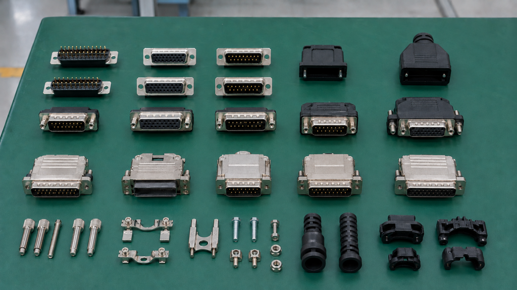
Contact Layout
The first practical check is the arrangement of the contacts. A standard-density 15-position D-Sub product may have two rows, while a high-density 15-position product uses three rows in a smaller contact pattern. Official component listings distinguish these as separate connector families, and product data for standard-density and high-density versions confirms differences in row count and physical configuration.
This distinction is easy to miss because commercial names are not always used consistently. Purchasing records, older equipment manuals and online product listings may apply “DB15” to more than one 15-contact format. The most reliable starting point is therefore a straight-on photograph of the mating face, supported by a connector part number or mating-equipment information whenever available.
The photograph should show all contacts, the D-shaped shell and the connector orientation. A second photograph from the cable-entry side helps identify the backshell and termination arrangement. When the cable connects to installed equipment, include the machine port and label each image clearly as either the equipment interface or the required cable connector.
A wrong contact layout cannot be corrected by changing the wiring. The connector body, mating dimensions, contact spacing and compatible backshell are different. Confirming this detail before quotation prevents the project from moving through sourcing and assembly with a component that will never fit the customer’s equipment.
Gender and Mating
Connector gender should be identified by the contacts. A male connector has pins, while a female connector has sockets. The surrounding metal shell can confuse people who do not work with D-Sub components every day, so “male” or “female” should be supported by a photograph, drawing or mating-part reference.
Both cable ends need their own definition. The required configuration may be male-to-male, male-to-female, female-to-female, DB15-to-open-wire or DB15-to-another connector family. When only one side is described, the manufacturer must either pause the quotation or introduce an assumption that may later change the price.
The equipment-side connector gives an important cross-check. A project team may describe the port from memory and accidentally request the same gender as the equipment interface rather than the connector that mates with it. A photograph of the port, equipment model or mating connector part number reduces that risk without requiring the customer to prepare a complete mechanical drawing.
Orientation also matters. A connector can have the correct gender but still be unsuitable because the mounting direction, screw position or cable exit interferes with a panel, enclosure or neighboring port. The mating condition should therefore be reviewed as a small mechanical system, not as an isolated connector.
Part Number and Termination
A manufacturer part number is usually the clearest connector definition because it can identify the contact layout, gender, termination, plating, hardware and shell configuration. Even so, the part number should be checked against the intended assembly process. Some D-Sub products are designed for printed circuit boards, while others use solder-cup, crimp or IDC terminations suitable for cable production.
Connectors that appear similar can also have different wire-size and current capabilities. Official Amphenol examples include standard-density 15-position solder-cup products with different current ratings, demonstrating that position count and shell appearance do not define the complete electrical capability.
When the specified part is controlled by an approved-vendor list, the quotation should follow that requirement. When alternatives are acceptable, the customer should state which characteristics cannot change. Useful comparison points include mating dimensions, gender, contact arrangement, termination style, wire-size range, contact plating, mounting hardware and electrical rating.
For replacement projects without a known part number, clear photos, basic dimensions and a physical sample may allow the engineering team to identify an appropriate component. The selected option should still be documented and approved before sample assembly so that the quotation and final drawing refer to the same connector.
Backshell and Locking
The backshell protects the terminations, supports the cable exit, manages strain relief and may form part of the shielding path. Typical options include assembled plastic shells, shielded metal shells and molded connector bodies. The required choice depends on installation space, cable diameter, grounding design, mechanical handling and appearance.
The quotation should define whether the cable exits straight or at an angle. For angled designs, a drawing is safer than the words “left” or “right,” because those directions change depending on the viewing side. The available installation envelope should also be measured, especially when the connector sits close to a cabinet wall, cover or adjacent interface.
Locking hardware must match the mating equipment. TE Connectivity’s D-Sub backshell information lists both 4-40 UNC and M3 thread options, as well as different cable-exit angles, which shows that these details are selectable rather than universal.
Cablivo’s documented connector review covers the model, gender, pin count, pitch, mating part, connector direction, cable exit, terminal match, shielding, overmolding, panel mounting, locking structure, availability and alternative options. This review is intended to identify mechanical and sourcing risks before sample production.
| Connector item | Common options | Information to submit | Selection value |
| Contact layout | Two-row or three-row | Mating-face photo and part number | Prevents incompatible connector selection |
| Gender | Male pins or female sockets | Details for both cable ends | Confirms mating compatibility |
| Termination | Solder cup, crimp or IDC | Connector datasheet | Matches production process and wire size |
| Backshell | Plastic, metal or molded | Shielding and space requirements | Controls protection and installation fit |
| Cable exit | Straight or angled | Drawing with viewing direction | Avoids enclosure interference |
| Locking | 4-40, M3 or another system | Mating hardware details | Allows secure equipment connection |
| Cable entry | Clamp or molded transition | Finished cable outside diameter | Prevents poor clamping or strain relief |
| Mounting | Cable-end or panel arrangement | Panel dimensions if relevant | Defines hardware and assembly method |
| Sourcing | Controlled part or approved equivalent | Substitution rules | Affects availability, MOQ and price |
| Appearance | Color, finish and logo | Approved sample or drawing | Supports product and brand consistency |
Which Pinout Details Matter?
A complete pinout must define every connection between both cable ends, including active contacts, unused contacts, crossed circuits, shared connections and shield termination. It must also state whether each connector illustration is viewed from the mating side or termination side. A connector description defines the hardware, but the pinout defines how the finished cable actually works.

Pin-to-Pin Map
A 15-contact D-Sub connector is a physical platform rather than a universal wiring standard. Industrial controllers, test instruments, motion systems, communication devices and legacy equipment can assign completely different functions to the same contact numbers. A cable that fits mechanically may still be electrically unusable when its pin-to-pin map does not match the connected equipment.
The clearest format is a wiring table showing the pin on End A, the circuit name, the corresponding pin on End B, the conductor requirement and any special processing note. Straight-through wiring should be written explicitly as 1-to-1, 2-to-2 and so on. Terms such as “normal wiring” or “standard wiring” leave too much room for interpretation.
Unused positions should be marked as NC, meaning no connection. Blank table cells can be mistaken for incomplete information rather than deliberate unused contacts. Crossed connections, internal bridges, looped contacts or shared returns should be shown separately so that production and inspection teams can verify them without relying on an email conversation.
When the backshell contains a resistor, diode, identification link or other component, that item should appear in both the circuit drawing and the BOM. For repeat production, the pinout needs a drawing number and revision so that engineering, purchasing, production and incoming inspection all refer to the same approved wiring definition.
View and Orientation
Pin numbering can be illustrated from the connector’s mating face or from its rear termination side. These views are mirrored, and the difference is one of the most common sources of wiring errors in manually prepared cable drawings. A technically correct list of pin numbers can still produce a reversed assembly when the viewing direction is not identified.
A simple connector-face illustration should be placed beside the pin table. It needs to mark pin 1, the top of the shell and the viewing direction. Clear descriptions include “viewed from mating side” or “viewed from solder-cup side.” Both ends should be illustrated separately, particularly when one connector is male and the other is female.
Photographs require similar care. An image can be rotated during document preparation, messaging or printing, so an arrow marked “top” is useful. The photo should also state whether it shows the cable connector or the mating equipment connector.
Sample inspection should compare the physical connector orientation with the approved diagram rather than relying only on an electrical continuity test. Continuity confirms that two physical contact locations are connected, but it cannot prove that the customer’s original numbering view was interpreted in the intended direction.
Shield and Ground
Specifying a shield is only half of the shielding instruction. The RFQ must also show where the foil, braid or drain wire connects. Possible arrangements include shell-to-shell bonding, connection at one end only, connection to a designated pin or an intentionally isolated shield at one side.
The correct arrangement belongs to the equipment grounding strategy. A cable manufacturer can review whether the proposed construction is practical, but it should not invent the customer’s chassis and signal-ground design. A useful note might state that the overall foil and braid connect to the End A metal shell while the shield is cut back and insulated at End B.
Backshell material and termination method must support the selected grounding plan. A metal hood may be appropriate when conductive shell continuity is required. A plastic hood may still be suitable when a drain wire terminates to a controlled pin and the shell is not part of the electrical path.
Shield termination also affects manufacturing time. It may require foil removal, braid preparation, drain-wire insulation, conductive tape, ferrules or additional continuity checks. Including these details at the RFQ stage allows the supplier to price the actual process instead of assuming a simple unshielded termination.
Electrical Limits
Power circuits should include operating voltage, continuous current, peak current and allowable voltage drop where relevant. These values help determine conductor gauge, contact suitability and insulation requirements. When one cable carries both power and signal circuits, the power conductors may need a larger cross-sectional area than the control or communication wires.
Signal-sensitive circuits may require twisted pairs, controlled impedance, dedicated returns or defined capacitance. These requirements should come from the connected system rather than being added automatically. A low-frequency switching circuit does not necessarily benefit from the same construction used for a higher-speed differential signal.
The current rating and acceptable wire size depend on the exact connector and contact. Official component examples show that 15-position D-Sub products with a similar outward description can use different contact constructions and electrical ratings.
The test plan should follow the electrical risk. Basic control cables may require continuity, short-circuit and pinout checks. Other assemblies may need shield continuity, resistance, insulation or hi-pot testing according to the approved product specification. Cablivo’s engineering scope includes wire-sequence confirmation and pinout review before sampling and production preparation.
| Pinout item | Required information | Practical example | Risk when omitted |
| Active contacts | Every used pin | Pins 1–8 active | Missing or extra circuits |
| Unused contacts | Mark each as NC | Pins 9–14 NC | Incorrect termination assumptions |
| Straight wiring | Full pin mapping | A1-B1, A2-B2 | Unexpected crossed wiring |
| Crossed wiring | Both contact numbers | A4-B7 | Equipment malfunction |
| Circuit function | Signal, power, return or ground | Pin 4: supply positive | Wrong gauge or pairing |
| Connector view | Mating or termination side | End A viewed from mating side | Mirrored pin assignment |
| Shield connection | Shell, pin, one end or both | Shield to End A shell only | Grounding and interference problems |
| Voltage | Nominal and maximum where needed | 24 VDC system | Unsuitable insulation selection |
| Current | Continuous and peak by circuit | 1.5 A continuous | Undersized conductors or contacts |
| Revision | Drawing number and revision | CAB-015 Rev C | Obsolete wiring used in production |
What Cable Construction Is Needed?
Cable construction should define the conductor count, wire gauge, internal pairing, shielding, jacket, outside diameter, flexibility, finished length and tolerance. These details control a large share of the material cost and determine whether the assembly can carry its electrical load, fit the backshell, resist interference and route correctly through the customer’s equipment.

Conductors and Wire Gauge
The number of conductors should follow the active circuits in the pinout rather than the total number of connector positions. A 15-contact connector may use all contacts, but another project may use only several signal lines, a power pair and a shield connection. Specifying unnecessary cores increases cable diameter and material cost without improving function.
Wire gauge should be assigned according to current, length, voltage-drop limits, contact termination range and mechanical requirements. Custom signal and control assemblies often use relatively small stranded conductors, while powered circuits may require larger sizes. The exact range must be matched to the selected connector and application rather than copied from another cable.
Larger wire is not automatically safer. It can make the cable thicker, less flexible and difficult to terminate inside small solder cups or crimp contacts. A larger cable may also exceed the backshell clamp range. Very small conductors create the opposite concern when they are expected to carry current over a long distance or withstand repeated handling.
When the correct gauge has not yet been selected, provide the operating voltage, continuous current, peak current, cable length and allowable voltage drop. The manufacturer can then evaluate a practical structure for customer approval. The RFQ should also state whether stranded copper, tinned copper or another controlled conductor is required.
Length and Tolerance
A finished cable length needs both a value and a measuring method. Possible references include mating face to mating face, backshell exit to backshell exit or visible jacket length. A specification such as “1,000 mm” can lead to noticeably different products when the end points are not shown on a drawing.
Tolerance should match the installation. A loose external connection may accept a broader length variation, while an internal cable running between two fixed points may need tighter control. Extremely tight tolerances can increase cutting, assembly and inspection effort, so they should be used when the equipment genuinely requires them.
Branch or breakout assemblies need dimensions for every leg. The drawing should identify the branch origin, individual leg length, exposed-wire section, strip length, terminal orientation, sleeve position and label position. These dimensions often matter more during installation than the overall cable length.
Longer versions may require more than a simple material adjustment. Voltage drop, signal behavior, cable weight, coil size and carton dimensions can all change. When several lengths are being purchased, each length should have its own SKU, quantity and packaging definition so that quotation and production records remain clear.
Shielding and Pairing
Shielding choices may include foil, braid, foil plus braid, individually shielded pairs or an overall shield. The selection should reflect the signal type, interference environment, cable movement, outside-diameter limit and grounding plan. Adding the maximum available shielding to every project can increase cost and stiffness without solving a real application problem.
Foil can provide broad coverage in a compact structure. Braid may offer a durable conductive path and additional mechanical support. Combined structures can be useful in more demanding environments, but they require additional materials and processing. Shield preparation may include foil removal, braid combing, drain-wire insulation, conductive tape or ferrule installation.
Twisted pairs should also be identified by circuit. When a pair carries differential or noise-sensitive signals, the drawing should state which conductors form the pair. Randomly twisting all cores together is not the same as maintaining controlled pairs through the cable.
Cablivo’s documented manufacturing base includes conductor preparation, high-speed stranding, insulation and jacket extrusion, braiding and foil-wrapping equipment. These capabilities allow different constructions to be evaluated, but the selected structure and acceptance criteria still need to follow the actual project.
Jacket and Flexibility
Jacket selection should be tied to routing, handling, abrasion, temperature, chemicals, appearance and market requirements. Possible material directions include PVC, TPE, TPU, PUR, silicone and PE, but no single material is automatically suitable for every DB15 assembly. Compliance claims also need support from the actual selected material and related supplier documentation.
The RFQ should include the desired color, outside diameter and surface expectations when these features are controlled. Outside diameter is especially important because it affects the backshell clamp, strain relief, cable gland, enclosure opening and minimum routing space. A technically suitable core can still fail the mechanical design when the completed cable is too thick.
The word “flexible” needs context. A cable that feels soft during installation is not necessarily designed for continuous movement. State whether the cable remains static, is occasionally repositioned or bends repeatedly as part of machine operation. Dynamic applications should include bend radius, motion direction and expected operating conditions.
A sample provides a practical opportunity to confirm cable feel, diameter, routing and connector transition before mass production. After approval, the final drawing, BOM and physical reference should agree so that production does not gradually drift away from the version tested in the customer’s equipment.
| Construction factor | Typical options | Main selection basis | Quotation concern |
| Active conductors | Project-specific up to connector capacity | Pinout and circuit functions | Avoids unnecessary cores |
| Wire gauge | Selected by current and signal needs | Current, length and contact range | Mixed gauges increase processing |
| Finished length | Short internal lead to multi-meter cable | Equipment routing | Measuring points must be defined |
| Length tolerance | Broad or controlled | Installation sensitivity | Tight tolerance adds inspection work |
| Pairing | Individual cores or twisted pairs | Signal requirements | Pair assignments must be documented |
| Shielding | None, foil, braid or combined | Interference and grounding | Termination method changes labor |
| Jacket | PVC, TPE, TPU, PUR, silicone or PE | Environment and handling | Compliance follows actual material |
| Outside diameter | Determined by full cable structure | Backshell and routing space | Oversized cable may not fit |
| Flex use | Static, occasional or dynamic | Equipment movement | “Flexible” alone is not measurable |
| Marking | Plain, printed or labeled | Identification and traceability | Artwork and position require approval |
How Will the Cable Be Used?
Application information tells the manufacturer what the cable must survive, not only what it must connect. Describe the equipment, cable function, installation path, movement, nearby interference, environmental exposure and service conditions. This context helps identify an unsuitable connector exit, insufficient shielding, weak strain relief or inappropriate jacket before the first sample reaches the customer.

Equipment and Function
Identify the equipment category and the role of the cable. Useful descriptions include an internal controller connection, an external service cable, a test-fixture lead, a signal link between two instruments or a combined power-and-control connection. The manufacturer does not need the customer’s entire product design, but it needs enough context to understand the consequences of an incorrect material or wiring assumption.
The equipment model, mating-port details and original cable information can provide valuable reference points. For older systems without complete drawings, send photographs of the equipment port, connector labels, installation area and existing cable. A working physical sample may help confirm mechanical construction, although its pinout should still be measured or verified against equipment documentation.
Replacement projects should state whether the new cable must be an exact reproduction or a functionally compatible redesign. An exact copy may need matching color, dimensions, hardware, labeling and appearance. A functional replacement may allow a more available connector, improved strain relief or another practical material, provided the customer approves the differences.
Explaining the cable’s function also helps separate critical requirements from historical details that no longer contribute to performance. This often produces a more practical specification and reduces the chance of paying to reproduce an obsolete feature that the new application does not need.
Movement and Routing
A cable that remains stationary inside a cabinet has different mechanical requirements from one attached to a moving arm, hinged panel or frequently handled test device. State whether the assembly is fixed, occasionally repositioned or repeatedly flexed during operation. The description should reflect actual use rather than relying only on the word “flexible.”
For moving applications, provide the minimum bend radius, approximate stroke, movement direction, speed and expected cycle requirement where available. These details influence conductor stranding, internal cable design, jacket material and strain relief. A cable that bends occasionally during installation is not automatically suitable for continuous motion.
The route through the equipment should show clamps, tie points, cable glands, sharp edges, heat sources and neighboring power conductors. Many failures begin near a connector because the cable is forced to bend immediately after the backshell or because a clamp concentrates stress in one location.
Installation clearance should also be measured around the connector. A straight backshell may extend too far into a shallow enclosure, while an angled design may solve the routing issue. The direction must be shown on a drawing so that the final connector does not exit toward a wall or adjacent component.
Environment and Protection
Describe whether the cable is used indoors, outdoors, inside a protected enclosure or in an exposed industrial area. Relevant conditions may include temperature changes, humidity, dust, moisture, sunlight, oil, cleaning chemicals, vibration or corrosive exposure. The goal is not to include every demanding condition, but to identify the ones that actually affect the product.
Operating, storage and shipping environments should be considered separately. A cable used in a controlled laboratory may still travel through hot or humid conditions and may need pin protection during international transport. Packaging can therefore solve a different risk from the cable jacket or connector body.
When sealing is required, review the full mated connection. A connector described as waterproof does not automatically make the cable assembly or equipment interface sealed. The backshell, cable entry, overmold, mating connector, panel mounting and test method all influence the final result.
Environmental tests should be connected to a defined requirement. Temperature and humidity, salt spray, insulation or flame-related evaluation may be discussed when relevant, but the method, parameters and acceptance criteria need to be confirmed. Cablivo’s fact base specifically requires testing to be selected according to the product, application and customer requirement rather than claimed as universal for every cable.
Sample Validation
The sample is where the written specification meets the real equipment. It allows the customer to confirm mating, locking, cable length, routing, flexibility, pinout, appearance, label position and handling before production quantities are released. A structured review is more useful than approving the sample only because it looks similar to the drawing.
The validation checklist should include connector fit, screw engagement, cable exit, installation clearance, conductor function, shield connection, length, label position and any project-specific test. When the assembly connects to proprietary equipment, a functional trial in the actual device may reveal issues that cannot be seen during a standalone continuity test.
Changes should be recorded on the drawing and BOM rather than left only in messages or marked photographs. A revised sample needs a clear revision reference so that the approved version becomes the production standard. Modifications may affect materials, tooling, testing, price and preparation time, so the new direction should be reviewed before another sample is made.
After approval, production preparation should use the final drawing, final BOM, approved sample and confirmed test requirements. Cablivo’s documented engineering scope includes requirement review, sample review, connector confirmation, DFM feedback, prototype development, sample revision, sample approval and production preparation.
| Application condition | Information to provide | Possible design response | Validation method |
| Fixed cabinet use | Route, clearance and nearby wiring | Shielding and exit-angle review | Trial installation |
| Repeated movement | Bend radius, stroke and cycle target | Flexible structure and strain relief | Project-defined bending test |
| Frequent mating | Expected connection frequency | Hardware and contact review | Connector-fit or life test |
| Outdoor exposure | Moisture, sunlight and temperature | Jacket and sealing review | Defined environmental evaluation |
| Vibration | Equipment and mounting condition | Secure screws and cable support | Mechanical inspection |
| Tight enclosure | Maximum connector envelope | Compact or angled backshell | Dimensional check |
| Power and signal | Current and signal assignments | Mixed gauges and shielding | Electrical and functional checks |
| Corrosive exposure | Chemical or salt conditions | Plating and metal-part review | Specified corrosion test |
| Replacement cable | Original sample and compatibility goal | Exact copy or approved redesign | Equipment fit and function |
| Long-term program | Forecast and revision plan | Controlled BOM and sample | First-article and batch inspection |
What Completes the DB15 RFQ?
A complete DB15 RFQ combines technical specifications with controlled files, quantities, testing, packaging, destination and revision status. Drawings, BOMs, connector datasheets and samples should agree. When some details are still unknown, the quotation should identify the assumptions clearly so that a preliminary estimate is not mistaken for a fixed production price.

Files and Revisions
A strong RFQ package usually includes an assembly drawing, pin-to-pin table, BOM, connector datasheets and relevant photographs. The assembly drawing should show overall dimensions, measuring points, connector orientation, backshell, cable exit, labels, tolerances and important mechanical details. The pinout should define every electrical connection, while the BOM identifies controlled components and materials.
Each file needs a drawing number, revision and date. Names such as “final version,” “latest drawing” or “new final 2” are difficult to control once the files pass through several departments. A structured document identifier makes it easier for engineering, purchasing, production and quality teams to confirm that they are using the same information.
A physical sample should be described accurately. State whether it is an approved production reference, an obsolete design, a failed part or only a visual example. The drawing and sample should be compared before quotation, and any conflict should be resolved rather than silently interpreted by the supplier.
When complete drawings are unavailable, the project can begin with connector photos, sample photos, cable length, application details and target quantity. The engineering review can then identify the remaining points that must be confirmed before sampling. This approach supports early development without pretending that incomplete information is already a finished production specification.
Quantity and Pricing
Provide the required sample quantity, first production quantity and expected repeat demand as separate figures. Prototype pricing often includes low-volume component purchasing, engineering review, setup and manual processing. Production pricing is based on a more stable material, tooling, testing and packaging plan, so the unit figures should not be compared without understanding the quantity basis.
For several lengths, colors, pinouts or connector combinations, prepare an SKU matrix. Ten versions with 100 pieces each create a different production and packaging workload from one version with 1,000 pieces. Separate item control may be needed for materials, labels, test fixtures, bags and carton marks.
The quotation should distinguish one-time costs from recurring unit costs. Tooling, custom test fixtures, packaging setup or artwork preparation may be listed separately. This makes future repeat-order pricing easier to understand and prevents a one-time development cost from being hidden inside the unit price.
Cablivo’s general MOQ starts from 500 pieces for many custom cable projects, while the final quantity depends on the connector, cable structure, materials, overmolding, tooling, packaging and order plan. A useful quotation should also show its assumptions, validity period and the specification changes that may require repricing.
Testing and Acceptance
The test plan should answer three practical questions: what will be tested, how the test will be performed and what result is acceptable. Writing only “100% test required” does not define whether the customer expects continuity, wire sequence, insulation, connector fit, shielding, dimensional checks or an equipment-level functional test.
Common checks for a DB15 cable assembly may include continuity, open and short circuits, pinout, wire sequence, polarity, shield continuity, connector fit, length, appearance, labels and packaging. Other tests such as hi-pot, insulation resistance, pull force, bending, connector life, temperature and humidity or salt spray should be added when they relate to the application.
The RFQ should state whether each check applies to every unit or to an agreed sampling plan. When a test report is required, define the report format, parameters, sample size and traceability information. Proprietary equipment may also be needed when the cable cannot be fully evaluated with a standard continuity fixture.
Acceptance criteria need to be measurable. “Good connection” depends on personal judgment, while “all specified circuits pass continuity, no unintended shorts are detected, and both connectors mate and lock with the approved interfaces” can be inspected consistently. Cablivo’s documented test directions include pinout, wire sequence, connector fit, pull force, bending and insulation-related checks according to project requirements.
Packaging and Delivery
Packaging protects the electrical product and preserves its identity. DB15 male contacts, screw hardware and metal backshell surfaces can be damaged or scratched during transport, so the packaging plan should consider protective caps, bags, ties, coil diameter, trays, dividers and carton arrangement where appropriate.
For multi-SKU or branded projects, provide the customer item number, barcode type, label artwork, country-of-origin wording, label position, bag quantity, carton quantity and carton mark. These files should be confirmed before production. A cable can pass every electrical test and still create a serious receiving problem when the wrong barcode or model label is applied.
The shipping destination should include the country, delivery location and any customer-specific documentation. Material declarations, inspection records, packing lists or other required files should be discussed during quotation rather than requested after the products have been completed.
Production timing depends on the product structure, connector availability, materials, tooling, order quantity, testing and packaging plan. The schedule should be confirmed after sample approval and specification release. Cablivo’s project-information checklist asks customers to provide drawings, sample photos, BOM, connector model, cable length, AWG, pinout, application, quantity, testing, packaging and destination details to support more accurate quotation and smoother project coordination.
| RFQ element | Preliminary information | Production-ready information | Project value |
| Connector | General description or photo | Approved part and mating confirmation | Reduces sourcing and fit risk |
| Pinout | Basic wiring statement | Controlled pin-to-pin drawing | Prevents electrical mismatch |
| Cable | Approximate length and type | AWG, structure, shield, jacket and tolerance | Stabilizes material pricing |
| Mechanical design | Reference image | Approved backshell, exit and dimensions | Prevents installation problems |
| Quantity | Rough estimate | Sample, first order and forecast by SKU | Improves price comparison |
| Testing | General functional requirement | Method, limits, frequency and report | Creates consistent acceptance |
| Packaging | Bulk-packing assumption | Approved label, bag, coil and carton plan | Reduces damage and SKU errors |
| Documentation | Uncontrolled attachments | Drawing number, revision and approval | Supports repeat production |
| Compliance | General market statement | Defined requirement and evidence | Prevents unsupported assumptions |
| Delivery | Country only | Destination and document requirements | Improves shipment preparation |
Final DB15 Cable Assembly RFQ Checklist
Before sending a request, review whether the project package answers the main technical and commercial questions. A missing detail does not always stop the conversation, but it should be identified as unresolved. The supplier can then provide a preliminary estimate with clear assumptions or request the information needed to prepare a production-oriented quotation.
- Exact 15-contact D-Sub layout and connector gender
- Connector part number or clear mating-face photographs
- Mating connector or equipment-port information
- Termination method and locking hardware
- Backshell material, size and cable-exit direction
- Complete pin-to-pin table with connector viewing direction
- Active, unused, crossed and bridged contacts
- Shield type and shield-termination method
- Voltage, current and relevant signal information
- Conductor count and wire gauge by circuit
- Cable length, measuring points and tolerance
- Pairing, shielding, jacket and outside-diameter requirements
- Static, occasional-flex or repeated-motion application
- Environmental and installation conditions
- Sample quantity, first production quantity and forecast
- Test methods, acceptance limits and reporting requirements
- Labels, barcodes, bags, coil method and carton plan
- Shipping destination and documentation requirements
- Drawing, BOM and sample revision status
- Contact person responsible for technical approval
Request a Custom DB15 Cable Assembly Quote
A useful quotation is not simply the lowest number returned by a supplier. It is a price built around the same connector, pinout, cable structure, test plan and packaging expectation that the customer intends to approve and purchase. The more clearly those elements are controlled, the easier it becomes to compare quotations, evaluate samples and move into stable production without repeated specification changes.
Cablivo is the overseas-facing brand of Shenzhen Tianxiaowei Electronics Co., Ltd., a Shenzhen-based custom cable, wire-harness and cable-assembly manufacturer with 18 years of industry experience, more than 20,000 square meters of factory space, a team of more than 1,500 people and three manufacturing bases. Its documented project support covers drawing review, connector confirmation, sample development, mass production, project-based testing, packaging, labeling and shipment coordination.
To request a custom DB15 cable assembly quotation, submit your drawing or sample photos, connector details, mating-part information, pinout, cable length, wire gauge, application, quantity, testing requirements, packaging plan and shipping destination. When some details are not yet available, share the information you already have and clearly mark the open points. The engineering team can review the project, identify the specifications that still need confirmation and discuss the next practical step toward sampling and production.



