Skip to content


A DB15 cable assembly can look deceptively simple on an RFQ: two connectors, a cable, a required length, and a quantity. In actual production, two assemblies that appear almost identical may use different 15-position connector layouts, pin assignments, conductor gauges, shielding structures, backshells, locking hardware, strain-relief designs, jacket materials, testing procedures, labels, and packaging. A quotation based only on “DB15 male to female, 2 meters, 1,000 pcs” therefore leaves several technical and commercial decisions unresolved.
For an accurate DB15 cable assembly quote, provide the exact connector configuration at both ends, connector part numbers or clear photos, pinout, cable length, conductor count and AWG, shielding, jacket requirements, application details, required tests, target quantity, packaging information, and any available drawing, BOM, reference sample, or approved specification.
The aim is not to create extra paperwork. A complete RFQ allows engineering, purchasing, production, and quality teams to evaluate one clearly defined assembly instead of making separate assumptions. A small omission can produce a large downstream problem. A team may negotiate unit price for days, only to discover during sampling that the connector density was interpreted differently, the shield termination was never defined, or the selected backshell cannot fit inside the equipment. The safest time to find those issues is before the quote becomes a purchase decision.
What Information Is Required for a DB15 Cable Quote?
An accurate DB15 quotation needs enough information to define the physical assembly, electrical connections, cable construction, acceptance criteria, and expected order conditions. A controlled drawing is the strongest starting point, but an original sample, connector photos, BOM, pinout, cable length, application information, and realistic production quantity can also support an initial engineering review when documentation is incomplete.

A usable quotation starts with three questions: what must be manufactured, how must the finished cable function, and under what conditions will it be purchased and accepted? Those questions sound basic, but each one controls several cost and manufacturing variables. The physical definition covers connector type, gender, backshell, hardware, cable exit, dimensions, and length. The electrical definition covers pin mapping, conductor structure, grounding, and shielding. Commercial requirements add quantity, testing, labeling, packaging, and any tooling needed before production.
For existing products, send every controlled document already available rather than rebuilding the specification from memory. A drawing, BOM, connector part number, cable specification, wiring table, label artwork, packaging file, and reference sample together create a much stronger technical baseline. For replacement projects where documentation has been lost, a physical sample can provide valuable mechanical information, but hidden details such as conductor gauge, shield construction, internal terminations, and insulation still need independent confirmation.
A useful RFQ also separates fixed requirements from open engineering choices. The DB15 interface and pinout may already be locked by the equipment design, while jacket material, cable OD, shielding method, or molded backshell remain open for review. Marking these items clearly gives the manufacturer room to evaluate suitable structures without silently substituting a controlled requirement. That distinction is especially important when comparing several quotations because each supplier should ultimately price the same technical scope.
| RFQ Item | Preferred Information | Minimum Useful Starting Point | Main Risk if Missing |
| Connector | Full part number for each end | Clear front and side photos | Wrong mating interface |
| Connector gender | Male / female for each end | Face photo plus description | Incorrect assembly |
| Pinout | Controlled pin-to-pin table | Existing wiring reference | Electrical mismatch |
| Cable length | Finished length in mm | Approximate required length | Installation problem |
| Conductors | Core count and AWG | Electrical load and application | Wrong cable construction |
| Shielding | Foil, braid, drain and termination | State whether shielding is required | EMI or grounding issue |
| Jacket | Material or operating conditions | Indoor, outdoor, moving or fixed | Poor application fit |
| Testing | Acceptance checks and criteria | Wiring verification requirement | Unclear quality standard |
| Quantity | Sample and production quantity | Planned first order | Inaccurate price basis |
| Packaging | Label and packing format | Bulk or individual packing | Requotation later |
RFQ Documents
A controlled drawing remains the clearest way to communicate the dimensions and interfaces that directly affect fit, function, and manufacturing. It can identify connector references, cable length, tolerance, label position, strain-relief geometry, cable exit, and revision level in one place. The drawing does not need to contain every workshop instruction, but the dimensions and characteristics controlled by the product design should be visible enough that different departments are not working from different interpretations.
The BOM becomes particularly important when the assembly uses a specified connector manufacturer, fixed backshell, terminal, cable material, screw set, sleeve, label, or other controlled part. If alternative components may be considered, state whether written approval is required before substitution. One sentence such as “alternatives require engineering approval” can prevent a supplier from treating a physically similar part as automatically acceptable. Revision numbers should also remain consistent across drawing, BOM, pinout, packaging artwork, and purchase documents.
Drawing or Sample
A complete drawing is preferable, but many real cable projects begin without one. Legacy industrial equipment, discontinued assemblies, replacement programs, and supplier-transfer projects often rely on an original cable as the main reference. A sample can reveal overall length, connector geometry, screw hardware, backshell dimensions, strain-relief shape, cable OD, label position, color, and physical handling characteristics that may never have been captured in the original purchasing documentation.
A sample cannot reliably disclose every hidden construction detail. Conductor gauge, insulation, foil coverage, braid structure, drain-wire connection, internal soldering, crimp details, and exact pin mapping need to be inspected or verified separately. When only photographs are available, include a straight-on connector face, both sides of the backshell, locking hardware, cable exit, complete cable, markings, labels, and the equipment-side mating interface whenever possible. Clear engineering-oriented photos are far more useful than a single product beauty shot.
Open Specifications
Not every parameter needs to be finalized before the first technical discussion. During new product development, a team may already know the mating interface, wiring function, cable length, and expected volume while material selection or overmold design is still under evaluation. The important step is to label open items honestly rather than allowing assumptions to harden into a quotation that looks more definite than the underlying specification.
If a particular connector manufacturer is mandatory, say so. If equivalent connectors can be reviewed, state the approval process. If shielding is required but the final structure remains open, describe the interference concern or grounding architecture. If cable flexibility matters more than a specific jacket material, explain the actual installation need. Clear distinction between “fixed” and “to be confirmed” gives engineering room to solve the right problem while keeping purchasing aware of which items may still affect price.
Quote Readiness
A project is generally ready for a meaningful production-oriented quotation once connector configuration, pinout, finished length, conductor structure, shielding requirement, test scope, and target quantity are substantially defined. Labels, packaging, tooling, and special inspection should also be included when they are part of the supplied product. A quote can still be issued earlier, but it is better treated as a budgetary estimate when several major technical variables remain open.
That distinction matters during supplier comparison. One quotation may include shield termination, locking hardware, molded strain relief, labeling, and wiring tests, while another appears cheaper because those items were never defined. Comparing the two numbers without aligning scope creates a false sense of cost advantage. A strong purchasing comparison begins only after all suppliers are pricing the same approved or substantially equivalent product definition.
Which DB15 Connector Details Must Be Confirmed?
DB15 connector confirmation should cover the 15-position contact layout, gender at each end, exact part number or mechanical reference, mating connector, backshell, locking hardware, cable exit, shielding connection, and overmolding requirement. The term “DB15” is used loosely in everyday sourcing, so pin count alone is not enough to guarantee that the selected connector will physically mate with the equipment.

Connector identification is one of the highest-risk steps in a DB15 RFQ because an apparently specific product name may still allow multiple interpretations. A cable can pass continuity and pinout testing yet fail immediately at installation if the contact arrangement, shell, gender, jackscrew hardware, or backshell geometry is wrong. For equipment replacement programs, connector confirmation should therefore be treated as an interface verification task rather than a purchasing description.
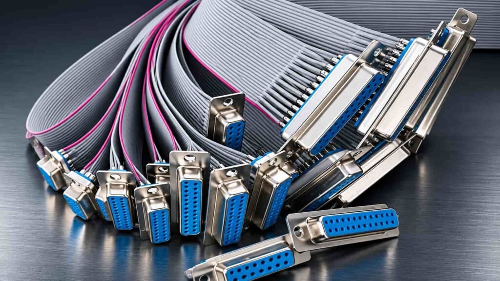
A common point of confusion is the difference between a standard-density 15-position D-sub layout and a high-density 15-position configuration. The standard-density arrangement uses two rows of contacts, while a high-density 15-position connector uses three rows. Both may be described informally with similar “15-pin” language in purchasing conversations, yet they are mechanically different and cannot be treated as interchangeable. The safest evidence is an exact manufacturer part number supported by a front-face photograph.
Mechanical details outside the contact insert deserve equal attention. Backshell length, width, material, cable exit, screw hardware, shielding treatment, and strain relief can determine whether an assembly fits beside neighboring connectors or inside a constrained enclosure. A replacement cable should therefore be checked against the actual mating equipment rather than only against a generic catalog image. When part numbers are unavailable, photographs of both the cable connector and equipment-side interface can remove much of the ambiguity before sampling.
| Connector Detail | What to Confirm | Practical Check | Consequence if Incorrect |
| Contact layout | Two-row or three-row 15-position layout | Front-face photograph | Connector cannot mate |
| Gender | Male or female | Inspect contact face | Wrong interface |
| Part number | Full manufacturer reference | Drawing or BOM review | Sourcing or fit variation |
| Mating part | Equipment-side connector | Equipment photo or drawing | Compatibility uncertainty |
| Backshell | Plastic, metal, assembled or molded | Dimensional check | Clearance issue |
| Locking hardware | Screw and mating arrangement | Inspect equipment | Cable cannot be secured |
| Cable exit | Straight or controlled orientation | Installation drawing | Routing interference |
| Shield termination | Shell or drain-wire arrangement | Wiring specification | Grounding inconsistency |
| Overmolding | None, existing or custom | Tooling review | Cost and tooling change |
Connector Density
The contact pattern should be confirmed before detailed price discussion because the wrong connector family invalidates almost every downstream decision. Counting fifteen contacts is not enough. A two-row standard-density D-sub and a three-row high-density 15-position connector use different geometries, so a cable made with one cannot simply replace the other even though both may be described casually as “15-pin D-sub.”
The full part number is the strongest identification method because it can also reveal options related to contact style, shell configuration, hardware, or mounting. When the part number is unknown, provide a straight-on photograph with all contact positions visible. For a replacement project, include the mating port on the equipment as well. That additional image often resolves questions around gender, density, hardware, and orientation before components are purchased for the first sample.
Gender and Mating
Male or female should be defined independently for every connector end. A DB15 assembly might be male-to-female, male-to-male, female-to-female, DB15-to-terminal, DB15-to-circular connector, or one branch of a larger custom harness. Assuming a standard configuration because it is common in another application creates unnecessary sampling risk.
Mating information is equally valuable. When a cable connects to existing industrial machinery, control equipment, laboratory instrumentation, or a panel-mounted interface, a photograph or drawing of the mating side helps engineers understand the real installation conditions. Clearance around neighboring ports, panel thickness, jack-screw arrangement, and cable routing can all affect whether a connector that looks correct on a desk actually fits inside the equipment.
Backshell and Locking
Backshell construction influences dimensions, shielding, strain relief, assembly process, cable exit, and unit cost. An assembled plastic hood, a conductive metal backshell, and a fully molded connector end can all use a similar D-sub contact interface while behaving very differently in production and in the installed equipment. For tight spaces, a maximum allowable envelope should be included in the mechanical drawing or clearly marked on reference photographs.
Locking hardware should be considered part of the interface rather than a small accessory. Screw thread, length, head design, and mating arrangement need to work with the equipment-side connector. A cable that connects electrically but cannot be secured may fail vibration, handling, or maintenance requirements. The safest specification therefore defines the complete mating system instead of naming only the connector insert.
Overmold Requirements
Overmolding can improve strain relief, connector protection, appearance consistency, and control of the cable exit after the structure has been approved. It can also introduce tooling cost and a different development process. Before evaluating a molded DB15 end, engineers need the connector geometry, cable diameter, required exit direction, maximum envelope, preferred material direction, surface expectations, color, and clearance around the mating equipment.
An existing molded cable provides useful reference information, but copying only its appearance is not enough. Internal anchoring, shield termination, strain-relief transition, and mold compatibility with the selected cable all matter. Cablivo’s engineering scope includes overmold structure review, tooling discussion, prototype development, and sample revision, allowing molded connector projects to be evaluated from mechanical feasibility through sample approval rather than treated as a cosmetic add-on.
How Should Pinout and Cable Construction Be Specified?
A DB15 cable should be defined by an explicit pin-to-pin map together with conductor count, AWG, finished length, shielding, jacket, cable diameter where relevant, and any special power, ground, signal, drain-wire, or shell connections. The connector identifies where the cable plugs in; the pinout and internal cable construction determine how the assembly actually functions inside the equipment.

Pinout errors are among the easiest cable problems to prevent in documentation and among the most disruptive to discover after assembly. A 15-position connector does not tell the manufacturer whether every pin is used, whether the wiring runs straight through, whether certain positions cross, whether several pins share a common ground, or whether the cable includes shell or drain-wire connections. Two assemblies can look identical from the outside and perform completely different functions because of their internal wiring.
The cleanest specification is a pin-to-pin table. Label both ends consistently, then show the destination of every populated contact. If a pin is intentionally unused, write NC rather than leaving the field blank. If a shield or drain wire connects to the shell, list the connection separately instead of squeezing it into a numbered-pin table. Revision control also matters because the final pinout used for testing should be the same revision used for quotation, sampling, and production approval.
Cable structure should be treated with the same discipline. AWG influences conductor cross-section, cable OD, flexibility, termination, current capability, voltage drop, and compatibility with connector contacts. A mixed-function cable may require different conductor sizes for signal, power, and ground rather than one uniform gauge. Shielding may cover the entire cable or selected conductor groups depending on the equipment design. Finished cable length should also have defined measuring points so that “2 meters” means the same thing to engineering, production, inspection, and purchasing.
| Parameter | Example RFQ Format | What It Controls | Review Priority |
| Pin mapping | A1-B1, A2-B7, A3-NC | Electrical function | Critical |
| Conductor count | Defined number of cores | Cable construction | Critical |
| AWG | Defined for each conductor group | Electrical and mechanical design | Critical |
| Finished length | 2,000 mm from defined reference points | Installation routing | Critical |
| Length tolerance | Project-defined tolerance | Fit and inspection | Project dependent |
| Shielding | Foil, braid, combined or none | EMI and grounding | Application dependent |
| Drain wire | Gauge and termination | Shield path | Required when applicable |
| Cable OD | Target or maximum OD | Backshell and routing fit | Mechanical projects |
| Jacket | PVC, TPE, TPU, PUR or specified material | Environment and flexibility | Application dependent |
| Label | Artwork, position and identification | Installation control | Program dependent |
Pin-to-Pin Mapping
A wiring table should use stable names such as Connector A and Connector B, with one row for every electrical path. Straight-through wiring can still be documented explicitly rather than relying on the phrase “standard DB15 wiring,” because a future revision or replacement order may otherwise depend on assumptions that were never formally approved. Crossed connections, shared grounds, jumpers, shell connections, and unused pins need equally clear notation.
Marking unused contacts as NC is a small detail with significant value. A blank field can mean “not connected,” “unknown,” or “not yet completed,” depending on who reads the document. A controlled wiring table removes that uncertainty and gives the test fixture or cable tester a direct acceptance reference. For repeat production programs, the same approved pinout can then support sample verification, production setup, final testing, and troubleshooting if field feedback occurs later.
AWG and Conductors
AWG should be chosen from actual electrical and mechanical requirements rather than from the DB15 connector name alone. Current, cable length, allowable voltage drop, conductor temperature, contact compatibility, cable flexibility, and overall diameter can all influence the appropriate gauge. Signal conductors may use relatively small gauges, while power or ground positions may require larger conductors, provided the selected contacts and cable structure can accommodate them.
When final conductor size is not yet locked, send the operating current, voltage, length, installation conditions, desired flexibility, and any space limitations. That gives engineering enough context to discuss suitable structures instead of selecting a gauge from an unrelated standard cable. Cablivo’s project-information framework specifically includes cable length, wire gauge, pinout, wire sequence, connector model, application, and target quantity as separate inputs because each controls a different part of the engineering and commercial review.
Shielding Structure
“Shielded DB15 cable” remains too broad for manufacturing because shielding can take several forms. A design may use foil, braid, combined foil-and-braid construction, separately shielded conductor groups, or another project-specific structure. The shield termination is just as important as the material itself. Connecting a drain wire or braid to one shell, both shells, a designated pin, or another ground point creates different electrical behavior.
For industrial or signal-sensitive applications, explain the interference or grounding concern when possible. That context helps engineering understand whether the priority is external noise rejection, internal crosstalk control, equipment grounding, or mechanical protection. Cablivo’s manufacturing fact base includes foil wrapping and high-speed braiding capability for cable structures requiring shielding, but the correct structure still has to be determined from the application, connector design, and approved electrical requirements rather than applied as a universal formula.
Length and Jacket
Finished cable length should use clearly defined measurement points. A nominal 2-meter assembly can be measured connector-face to connector-face, backshell to backshell, or by cable-only length, and the difference becomes more noticeable with larger molded or assembled D-sub ends. Dimensions should therefore be stated in millimeters when fit matters, together with a tolerance based on the actual installation requirement rather than an arbitrarily tight production target.
Jacket material should also follow the use environment. PVC, TPE, TPU, PUR, silicone, PE, XLPE, and other materials can offer different combinations of flexibility, abrasion behavior, environmental resistance, processing characteristics, appearance, and cost. Material selection should be based on application conditions and verified material documentation. Cablivo’s factual guidance explicitly avoids treating any one material as suitable for every project or claiming universal compliance without supporting documents.
What Testing and Application Details Are Needed?
A DB15 cable RFQ should state what equipment the cable connects, the electrical and mechanical functions it performs, the environment in which it operates, and how the finished assembly will be accepted. Continuity and pinout verification are common for custom multi-pin cables, while connector fit, pull force, insulation, bending, environmental, labeling, or packaging checks should be added when the application genuinely requires them.

Testing has value only when it addresses a real failure mode. A long test list may look impressive in a specification but can add cost, time, and complexity without improving the assembly if the tests are unrelated to the application. The stronger approach begins by identifying what could cause the cable to fail in service, then selecting inspection and verification methods that directly address those risks.
Application context often reveals requirements that cannot be seen from the drawing alone. A fixed cable inside a control cabinet may prioritize wiring accuracy, connector fit, length, and labeling. An external cable that is handled every day may require greater attention to strain relief and bending. A cable routed near motors or drives may introduce shielding and grounding questions. Equipment with tightly spaced interfaces can impose connector-envelope limitations that never appear in a generic connector catalog.
Electrical information should be supplied when it affects conductor selection, insulation, shielding, or test methods. Voltage, current, signal function, grounding arrangement, and any controlled signal requirements are more useful than copying a generic D-sub rating from an online product listing. The completed assembly is a system of connector contacts, conductors, insulation, cable length, shielding, termination, and operating environment, so acceptance criteria need to reflect the actual product rather than one isolated component.
| Application Concern | Information to Provide | Typical Verification | When It Matters |
| Wiring accuracy | Approved pinout | Continuity and pinout check | Custom wiring |
| Connector fit | Mating interface | Connector-fit check | Existing equipment |
| Joint strength | Termination and strain-relief requirement | Pull-force test if specified | Mechanical load |
| Insulation | Voltage and safety requirement | Hi-Pot or insulation test if required | Electrical safety projects |
| Flexing | Bend location and movement conditions | Bending evaluation if required | Moving equipment |
| Environment | Temperature, humidity or corrosion exposure | Project-specific environmental test | Industrial or outdoor use |
| Identification | Label artwork and position | Label inspection | Multi-cable systems |
| Packaging | Protection and carton requirements | Packaging inspection | Export and bulk shipment |
Equipment Application
A useful application description does not need to expose confidential system architecture. Statements such as “fixed connection inside an industrial controller,” “external interconnect between machine modules,” or “replacement cable for legacy test equipment” already provide valuable engineering context. Installation photographs and interface drawings become particularly useful when connector clearance, routing, vibration, movement, or enclosure dimensions may affect the assembly.
Application information also helps separate genuine engineering requirements from habitual specifications. A very flexible premium jacket may be valuable in moving machinery but unnecessary for a stationary cable inside an enclosure. A large metal backshell may provide shielding benefits but create a mechanical conflict in a dense panel. By explaining how the cable is actually used, the project team gives the manufacturer enough information to challenge unnecessary cost while protecting characteristics that directly affect installation and reliability.
Electrical Requirements
Voltage, current, signal type, grounding arrangement, and relevant functional information should be included whenever they influence conductor gauge, insulation, shielding, connector contacts, or testing. If several conductor groups perform different functions, identify those functions in the pinout. Power, ground, analog, digital, control, or other circuit roles can then be reviewed separately without disclosing more system information than necessary.
Generic connector ratings should not replace assembly-level engineering data. A particular connector family may have published ratings, but the usable performance of the completed cable still depends on conductor size, contact type, cable length, termination process, insulation system, bundling, temperature, and operating conditions. The project specification should therefore define the actual electrical expectations and acceptance method instead of assuming that one catalog value automatically applies to every custom DB15 cable.
Test Requirements
Continuity and wire-sequence verification are logical checks for custom multi-pin assemblies because they directly confirm whether the approved wiring has been reproduced correctly. Connector-fit checks may be important for replacement cables or tight mechanical interfaces. Pull-force testing can be relevant to crimped or mechanically stressed terminations, while Hi-Pot or insulation testing may be appropriate when a defined electrical safety requirement exists.
Additional reliability testing should follow the project rather than being applied automatically. Cablivo’s documented testing capability includes continuity, pinout, connector fit, pull force, tensile, bending or swing, connector-life, Hi-Pot or insulation, salt spray, temperature and humidity, appearance, labeling, packaging, and pre-shipment inspection discussions. The same fact base also requires test parameters to be confirmed according to product type and application rather than claiming that every cable automatically receives every available test.
Environmental Conditions
Temperature, humidity, movement, abrasion, oil, corrosion, indoor or outdoor installation, and other environmental factors can change the recommended cable structure and material discussion. A stationary laboratory cable and a cable installed on industrial equipment may share the same connector while requiring very different jackets, strain relief, shielding, and validation. Environmental requirements should therefore appear in the RFQ early enough to influence material and structural choices.
Compliance should be handled with the same discipline. Instead of asking whether “all DB15 cables are certified,” identify the actual standard, material restriction, declaration, documentation, or test required for the target market or equipment program. Material compliance can then be checked against the proposed components and available supplier documents. Unverified medical, military, UL, RoHS, REACH, flame-retardant, or other claims should never be assumed solely because another cable with a similar connector carries them.
How Do Quantity and Packaging Affect the Quote?
Sample quantity, production volume, forecast, tooling, overmolding, labeling, packaging, and shipping requirements all affect the commercial structure of a DB15 cable quote. The same electrical design can carry different unit economics at prototype, pilot, and repeat-production stages because component purchasing, material preparation, setup, testing, tooling, labeling, and packaging costs are distributed differently across each quantity.

A quotation without realistic quantity information is commercially incomplete. Connector purchasing, cable-material preparation, process setup, inspection planning, packaging, and tooling decisions all depend to some extent on expected volume. A prototype run exists mainly to validate the engineering definition, while a recurring production program requires a stable supply plan and repeatable manufacturing process. The two stages should not be treated as identical simply because the physical cable looks the same.
Cablivo’s documented MOQ starts from 500 pieces for many custom cable projects, while the final minimum depends on connector type, cable structure, materials, overmolding, tooling, packaging, and order quantity. Prototype requirements should be discussed separately because engineering samples serve a validation purpose and may involve component sourcing, manual preparation, temporary fixtures, or tooling evaluation that does not scale directly with production quantity.
Packaging deserves equal attention because it can add real material and processing work. A cable placed in bulk protective packaging is commercially different from one requiring an individual bag, cable tie, barcode label, serial identification, connector protector, printed insert, private-label box, carton mark, or controlled pack quantity. For industrial projects, functional protection during international shipment may matter more than retail presentation, especially when heavy D-sub shells and locking screws could damage adjacent assemblies.
| Commercial Factor | Example Information | Quote Impact | Procurement Value |
| Prototype quantity | Number required for validation | Setup and engineering work | Supports sample approval |
| First order | 500, 1,000, 5,000 pcs or actual quantity | Material and production planning | Real unit-price basis |
| Forecast | Monthly, quarterly or annual estimate | Sourcing preparation | Long-term supply planning |
| Connector source | Fixed brand or reviewed alternative | Component cost and availability | Reduces substitution risk |
| Tooling | Existing or new mold | One-time tooling cost | Separates NRE from unit cost |
| Labeling | Standard, custom or serialized | Printing and inspection | Identification control |
| Packaging | Bulk, individual or private label | Material and labor | Fair quotation comparison |
| Connector protection | Caps, separators or individual bags | Packaging cost | Reduces transit damage |
| Destination | Country and shipping plan | Export preparation | Delivery planning |
Sample Quantity
Prototype quantity should reflect how the assembly will actually be validated. One project may need only several pieces for engineering fit and continuity checks, while another may distribute samples among design engineering, quality, manufacturing, field testing, and system-validation teams. Providing that number at the beginning helps the manufacturer distinguish sample preparation from the later mass-production commercial structure.
Sampling is also the stage where connector mating, pinout, length, cable handling, backshell clearance, molded appearance, labels, and test methods can be verified before a larger material commitment is made. Sample time should therefore be confirmed after reviewing connector availability, cable materials, tooling, drawing maturity, and test requirements. Cablivo’s documented project guidance intentionally avoids fixed promises such as universal three-day or seven-day sampling because development time depends on the actual structure and supply conditions.
Production Quantity
State the planned first production order and provide a realistic program forecast when one exists. A forecast does not need to function as a binding purchase commitment to be useful. It helps the manufacturer understand whether the cable is a one-time replacement part, a pilot run, a seasonal order, or a long-term component used in recurring equipment production.
Volume affects connector purchasing, cable-material preparation, production scheduling, inspection setup, packaging-material procurement, and the economics of custom tooling. When demand is not fully known, request pricing at realistic volume breaks that reflect plausible purchasing scenarios rather than arbitrary large quantities. A 500-, 1,000-, or 5,000-piece comparison can be useful only if those quantities are relevant to the project. Artificially high tiers may produce attractive numbers that never become applicable to an actual purchase order.
Labels and Packaging
Labels and packaging should be defined before final quotation rather than added after the sample has been approved. Cable identification may include a part number, revision, barcode, serial number, orientation marker, equipment identifier, or customer-controlled artwork. The specification should state label material where controlled, dimensions, position, readable orientation, print content, and any verification requirement.
Packaging can serve both presentation and protection. D-sub connectors have metal shells and protruding locking hardware that can contact neighboring products during transport. Individual bags, separators, connector protection, defined coil diameter, cable ties, inner boxes, or other protective methods may therefore be appropriate depending on cable length and shipment method. Packaging requirements also affect labor, consumables, carton configuration, and inspection, so two supplier quotations should not be compared as equivalent when their packing scope is different.
Tooling and Overmolding
A custom molded DB15 backshell can introduce a one-time tooling cost in addition to the recurring cable unit price. The requirement depends on connector geometry, cable OD, strain-relief design, exit direction, desired external shape, surface finish, maximum dimensions, color, and whether an existing tool can safely accommodate the selected components. Tool compatibility should be confirmed rather than assumed from a visually similar cable.
Purchasing teams benefit from separating tooling from recurring unit cost because the two expenses behave differently across the program life. The approved sample becomes particularly important for molded projects because it establishes connector fit, cable exit, molded dimensions, surface appearance, strain relief, and handling before mass production. Cablivo’s engineering and tooling resources support overmold structure review, mold feasibility discussion, prototype development, modification, and production preparation for projects that require a controlled molded connector structure.
Requoting Risk
The most effective way to reduce repeated quotations is to expose every cost-sensitive requirement before the supplier is asked for a final production price. Changing connector brand, AWG, shield structure, backshell, molded geometry, length tolerance, test plan, labeling, or packaging after the original quotation can legitimately alter material cost, process time, tooling, or sourcing conditions. Keeping those decisions visible allows price changes to be understood rather than treated as unexplained supplier behavior.
A disciplined RFQ also makes supplier comparison more meaningful. All quotations should ultimately refer to the same connector configuration, pinout, cable structure, length, testing scope, quantity, tooling treatment, label requirements, and packaging plan. The goal is not to identify the lowest number written in the first email. The goal is to understand the cost of the DB15 cable assembly that engineering intends to approve and production intends to purchase repeatedly.
Request a Custom DB15 Cable Assembly Quote
A useful DB15 cable quotation begins with project data rather than price alone. If a controlled drawing and BOM already exist, send them together with the pinout and quantity. If the project is based on an existing cable, provide clear sample photos or a reference sample together with the known wiring and application information. When the design is still developing, start with the connector configuration, cable length, AWG or electrical requirement, pinout, shielding need, target quantity, application environment, and any available equipment-side interface information.
Cablivo is the overseas-facing brand of Shenzhen Tianxiaowei Electronics Co., Ltd., a Shenzhen-based custom cable, wire harness, and cable assembly manufacturer with 18 years of industry experience, 20,000+ square meters of factory space, a 1,500+ person team, and 3 manufacturing bases. Its documented project scope covers requirement review, drawing and BOM review, connector confirmation, pinout review, material discussion, sample development, mass-production preparation, testing, packaging, labeling, and shipment coordination.
For a DB15 cable assembly inquiry, send the information already available rather than inventing missing specifications. Useful files and data can include a drawing, BOM, reference sample or photos, exact connector model, male or female configuration, mating connector, pinout, finished cable length, AWG, shielding requirement, jacket requirement, operating application, testing criteria, sample quantity, production quantity, labeling file, packaging requirement, and shipping destination. Unknown fields can remain marked to be confirmed so engineering review focuses on the real open questions.
A DB15 cable may represent only a small part of a larger machine, instrument, or control system, yet connector fit, pin assignment, shielding, conductor structure, strain relief, labels, and packaging can determine whether installation proceeds smoothly or becomes another engineering problem. Starting the quotation with complete technical evidence creates a clearer path from RFQ to sample approval and from approved sample to repeatable production.