 Skip to content


A waterproof cable assembly can look surprisingly simple on a drawing. There may be one cable, two connectors, a molded transition, and a short note saying “waterproof.” The problem is that this single word can hide most of the decisions that determine whether a quotation is realistic. A cable exposed to occasional outdoor rain is not automatically the same project as one subjected to repeated washdown, temporary immersion, condensation, vibration, or changing temperatures. Connector sealing, jacket selection, cable outside diameter, conductor size, pinout, overmolding, test conditions, and production quantity can all change the cost and manufacturing approach.
To quote a waterproof cable assembly accurately, a manufacturer normally needs the available drawing or sample information, connector and pinout details, cable length and AWG, electrical requirements, waterproof and sealing requirements, application environment, materials, overmolding details, testing criteria, target quantity, packaging requirements, and any required documentation or compliance information. Clear specifications reduce assumptions and make the quoted product closer to the assembly that will eventually be sampled and produced.
Not every project begins with a perfect engineering file. Some arrive with a complete drawing and BOM, while others begin with an old cable, several connector photos, a target length, and a note explaining where the product is used. That is not necessarily a problem. The real risk appears when missing information is silently guessed. A reliable RFQ process identifies what is already confirmed, what remains open, and which decisions must be settled before a preliminary price becomes the basis for tooling, sampling, and mass production.
What Documents Should You Send?
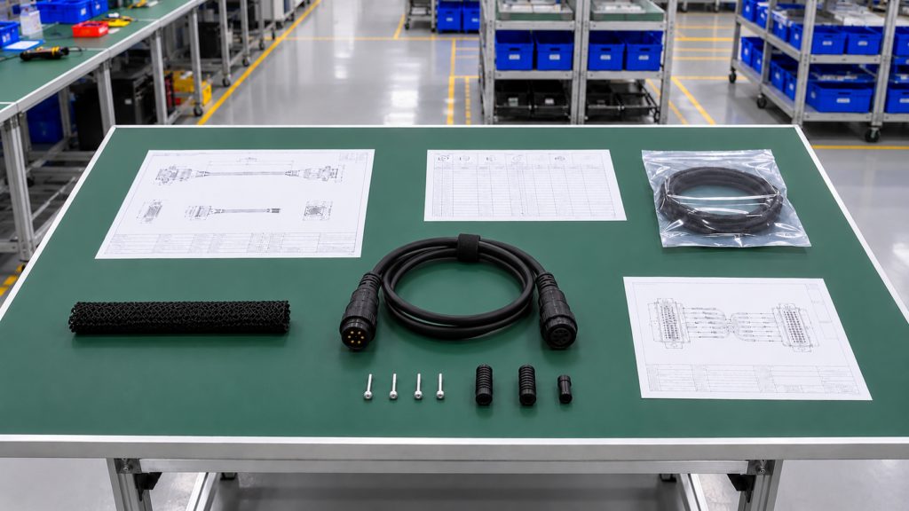
For an accurate waterproof cable assembly quote, send the latest drawing, BOM, wiring diagram or pinout, connector information, sample photos, and any existing product specification. These files help confirm dimensions, materials, wiring, sealing interfaces, and production requirements before pricing. If complete drawings are unavailable, clear photographs, existing samples, and basic application details can still provide a practical starting point for engineering review.
Do You Need a Drawing, BOM, or Sample?
A drawing is usually the most efficient starting point because it brings dimensions, connector orientation, cable length, tolerances, branch positions, labels, and assembly details into one controlled reference. For a straightforward point-to-point waterproof cable, a clear 2D drawing may provide enough information to begin a technical review. For a multi-branch harness, mixed conductor structure, molded transition, or several different connectors, additional supporting documents become more important because a drawing alone may not describe every material and purchasing requirement.
A BOM is particularly useful when the project already specifies exact connectors, terminals, wire types, seals, heat-shrink tubing, protective sleeves, labels, or molded materials. It allows engineering and sourcing teams to distinguish between components that are mandatory and those that remain open for equivalent selection. This matters because visually similar waterproof connectors can use different seals, contact systems, cable-entry ranges, backshells, or mating configurations, and those differences can affect both the quotation and the final installation.
A physical sample can be just as valuable, especially when an existing cable has already worked successfully in the field but the original technical documents are incomplete. A sample can reveal molding geometry, actual flexibility, connector keying, jacket feel, strain-relief shape, cable exit direction, label position, and assembly details that may never have been recorded in an old drawing. Replacement projects frequently depend on this kind of comparison before a new supplier can understand what should remain unchanged and what should be improved.
When several references are provided, identify which one has priority. If an existing sample differs from a revised drawing, the manufacturer should not have to guess which version controls the quotation. A short revision note can prevent an old cable from being copied into a new project or a superseded drawing from being treated as the production specification.
| RFQ Source | Best Used For | Information It Can Confirm | Main Risk When Missing |
| 2D drawing | New or controlled designs | Length, dimensions, orientation, tolerances, labels | Wrong dimensions or installation fit |
| BOM | Production-ready projects | Connectors, terminals, cable, seals, materials | Wrong component or sourcing assumption |
| Wiring diagram | Multi-core assemblies | Circuit relationship and branch logic | Incorrect wiring structure |
| Pinout | Connectorized assemblies | Pin-to-pin mapping and polarity | Device connection failure |
| Physical sample | Replacement projects | Geometry, flexibility, molding and connector fit | Hidden construction details missed |
| Sample photos | Early RFQ review | Appearance, connector type, cable route | Internal structure remains uncertain |
| Packaging file | Brand or multi-SKU programs | Labels, protection, carton requirements | Repacking or SKU errors |
What Connector Details Are Required?
“Waterproof connector” is not a complete connector specification. If a known model is required, provide the manufacturer, series, and exact part number whenever possible, together with gender, pin count, mating connector, coding, locking style, key orientation, and cable exit direction. Two connectors can appear almost identical in a product photograph while using different shell dimensions, key positions, threads, inserts, terminals, or sealing components. Selecting the wrong version can result in a cable that is electrically correct but mechanically impossible to install.
The mating side deserves equal attention. Some cable projects provide only the connector fitted to the cable while leaving the equipment-side interface unclear. For sealed assemblies, the waterproof function may depend on the relationship between both mating halves, an O-ring, a gasket, a backshell, or another sealing component. If the mating connector is already installed on the customer’s equipment, its part number or clear photographs can prevent unnecessary identification work during sampling.
Cable entry is another practical concern. Many sealed connector systems work within a defined cable outside-diameter range. If the project later changes from a small unshielded cable to a larger shielded construction, the original rear seal, gland, or molded geometry may no longer be suitable. This is one reason connector selection and cable construction should be reviewed together rather than treated as separate purchasing items.
If the exact connector model is unknown, send close-up photographs of the mating face, rear cable entry, locking mechanism, markings, and connector orientation. Including a ruler or caliper in one image can help establish scale. Photographs are valuable for preliminary identification, but the final model should still be confirmed before tooling or production specifications are released.
What Pinout Information Should You Provide?
Pinout information tells the manufacturer how each conductor must connect between the two ends of the assembly. For multi-core waterproof cables, a useful pinout identifies each connector cavity, corresponding conductor, wire color or identification number, opposite termination, polarity, and circuit function where applicable. This becomes especially important when the cable combines power, ground, signal, control, or shielding connections inside one jacket.
Viewing direction is a frequent cause of avoidable mistakes. A connector shown from the mating face can appear mirrored when compared with the cable-entry side. Drawings should therefore state whether the pin diagram is viewed from the front mating face, rear termination side, or another defined reference. Without this note, an otherwise clear diagram can be interpreted in two different ways.
Pinout information also affects the quotation because it can reveal whether the cable needs mixed AWG conductors, twisted pairs, shield terminations, drain wires, special crimp contacts, soldered terminations, or different wire colors. A four-core cable in which every conductor has the same function is a different manufacturing problem from a four-core assembly containing two heavier power conductors and two smaller signal conductors.
| Pinout Field | Example Information | Quotation Value |
| Connector cavity | Pin 1, Pin 2, Pin 3, Pin 4 | Defines termination position |
| Wire identification | Red, Black, WH-01, WH-02 | Supports assembly control |
| Circuit function | +24 V, GND, Signal A, Signal B | Clarifies electrical use |
| Opposite termination | J1-1 to J2-3 | Defines point-to-point wiring |
| Wire gauge | 18 AWG power, 24 AWG signal | Affects cable and terminal choice |
| Shield connection | Shield to shell at one end | Defines shield termination |
| Viewing direction | Mating-face view | Reduces mirrored pinout errors |
What If Your Files Are Incomplete?
Many real projects begin before a complete production drawing exists. An engineering discussion can still start with connector photographs, approximate cable length, wire count, application, waterproof expectation, target quantity, and a clear explanation of what the existing product must do. The important distinction is between an incomplete RFQ and a quotation that hides unverified assumptions.
For example, an equipment manufacturer may know that an existing cable is approximately 1.5 meters long and connects an outdoor sensor but may not know the exact conductor gauge or connector part number. That information can support an initial review, but it should not be treated as a finished manufacturing specification. Missing items such as pinout, cable OD, material, sealing structure, and test requirements can then be identified before the project proceeds to a controlled sample.
A useful RFQ process therefore separates confirmed information from open information. Customers do not need to delay a project until every detail is perfect, but they should expect the manufacturer to ask focused questions before final quotation or sampling. That approach usually produces a more dependable cost basis than issuing a fast price against a product that has not yet been clearly defined.
Which Waterproof Requirements Must Be Defined?
Waterproof requirements should describe the actual exposure condition, sealing interfaces, connector configuration, installation environment, and required validation method. A general statement such as “waterproof cable” does not provide enough information for dependable pricing. The manufacturer needs to understand where water may reach the assembly, how severe the exposure is, which interfaces must remain sealed, and how acceptable performance will eventually be evaluated.
Is an IP Rating Enough?
An IP requirement is useful when the project already has a defined protection target, but it should not replace a description of the real application. Two cables may both be described as requiring water protection while operating in very different environments. One may sit outside beneath a cover and encounter occasional rain. Another may be washed repeatedly as part of routine equipment cleaning. A third may be installed inside an enclosure where condensation and humidity are more important than direct water pressure.
The published protection level of an individual connector should also not automatically be treated as the performance of the complete finished cable assembly. A final assembly includes the connector mating interface, rear cable entry, jacket, seal, overmold, strain relief, and the specific manufacturing condition in which those parts are combined. A strong connector cannot compensate for an unsuitable cable diameter, poorly matched seal, or incorrectly designed cable-entry structure.
If a particular protection level is mandatory, provide the project requirement together with the intended test or acceptance condition. If the requirement is still being established, describe the operating environment first. Choosing an impressive rating without understanding the real exposure can lead to unnecessary cost on one project and inadequate protection on another.
What Water Exposure Should You Specify?
“Outdoor use” is too broad to define a waterproof cable assembly. A useful RFQ explains what actually happens to the product. The cable may experience occasional splash, direct rainfall, standing water, temporary immersion, repeated washdown, condensation, high humidity, or a combination of these conditions. Installation orientation is also worth describing because an upward-facing connector or cable entry can collect water differently from the same assembly installed horizontally or facing downward.
Frequency matters as well. A cable exposed to rain several times each year does not necessarily face the same material and sealing demands as a cable cleaned every day. Equipment located near coastal areas may add corrosion concerns that a normal inland outdoor installation does not have. The RFQ does not need to become a laboratory report, but it should identify the environmental conditions that are likely to influence construction.
If the connector is regularly unplugged, clarify whether waterproof protection is required only when the connector is fully mated. Some connector systems depend on the mating half to complete the seal. Where an unmated connector must remain protected outdoors, a sealing cap or other protective strategy may need to be discussed separately.
| Exposure Condition | Information to Provide | Main Engineering Concern |
| Outdoor rain | Orientation, drainage, UV exposure | Water collection and jacket durability |
| Occasional splash | Direction and frequency | Connector and cable-entry sealing |
| Temporary immersion | Required project depth and duration | Complete sealing integrity |
| Frequent washdown | Cleaning condition and frequency | Seal durability and connector protection |
| High humidity | Temperature and condensation condition | Moisture ingress |
| Coastal environment | Salt and humidity exposure | Corrosion of metallic components |
| Enclosed equipment | Condensation and drainage | Internal moisture accumulation |
Which Sealing Details Matter?
A waterproof cable assembly should be considered a system of possible water-entry paths rather than a normal cable fitted with a waterproof connector. Leakage can occur around the connector mating interface, cable gland, rear seal, O-ring, cable jacket, overmold transition, enclosure entry, or branch junction. The manufacturer therefore needs to understand which interfaces belong to the cable assembly and which sealing functions are provided by the customer’s equipment.
Cable outside diameter deserves special attention because many connector seals and glands compress around a defined diameter range. Changing conductor count, adding shielding, increasing jacket thickness, or replacing one jacket material with another can alter the finished OD. A change that appears minor from an electrical perspective can therefore require another seal, gland, backshell, or molded design.
The jacket surface and material can also influence how the assembly behaves at the sealing interface or overmold transition. A material selected only for flexibility may not necessarily provide the best combination of adhesion, environmental resistance, diameter control, and manufacturing consistency required by the final design. Material and sealing decisions are therefore more reliable when reviewed together.
How Should Overmolding Be Defined?
Overmolding can provide strain relief, connector protection, sealing support, repeatable geometry, and a controlled cable exit, so it should be treated as a functional part of the assembly rather than cosmetic plastic. The RFQ should show the approximate molded envelope, cable exit direction, installation restrictions, connector areas that must remain exposed, and any material or hardness requirement already fixed by the design.
Available installation space is often overlooked. A large overmold may provide excellent strain relief but fail to fit inside a recessed housing or narrow equipment channel. Conversely, an extremely short, rigid molded transition may fit neatly but offer different bending behavior from a longer flexible strain-relief design. The correct geometry depends on how the product will be installed and handled.
For a new custom molded structure, tooling may become a separate quotation factor. The manufacturer therefore needs to know whether the project can use an existing mold, requires modification, or needs an entirely new molded shape. Clarifying this early prevents the unit price from being mistaken for the total development cost.
| Overmold Detail | Information to Specify | Quotation Impact |
| Molded length | Target or maximum envelope | Material and tooling |
| Cable exit | Straight, side, angled | Mold structure |
| Connector exposure | Areas remaining accessible | Mold boundary |
| Cable OD | Actual or target range | Cavity and sealing fit |
| Material | Required material if fixed | Processing and material cost |
| Strain relief | Flexibility requirement | Geometry and tooling |
| Custom marking | Size and position if required | Mold design |
| Tooling status | Existing, modified, or new | Development cost |

What Cable Specifications Are Needed?
An accurate quote requires the cable construction that determines electrical performance, mechanical behavior, sealing compatibility, and production cost. Provide overall length, conductor count, wire gauge, conductor requirement, cable outside diameter, jacket material, shielding, color, flexibility, and any critical tolerances. Voltage, current, signal requirements, and installation restrictions should also be included so the cable can be evaluated as part of the complete equipment connection.
What Length and AWG Should You Specify?
Cable length is one of the easiest values to provide and still one of the most common causes of revision. A drawing should show exactly where the measurement begins and ends. For a connectorized cable, clarify whether the stated length includes connector bodies, stops at the rear of each connector, or refers only to exposed cable. Multi-branch and Y-split assemblies should identify each segment separately instead of relying on a single overall dimension.
Wire gauge should reflect both electrical load and the limitations of the selected terminal or connector. Higher current may require a larger conductor, while signal circuits inside the same cable may use smaller conductors. Increasing conductor size can also change cable OD, flexibility, weight, terminal compatibility, and the sealing range of the connector. AWG is therefore not an isolated specification.
Length tolerance should be practical rather than automatically tight. A cable routed loosely between two pieces of equipment may tolerate more variation than a short cable installed into a compact enclosure. Unnecessarily narrow tolerances can increase manufacturing control requirements without improving the finished application.
| Cable Item | Example RFQ Format | What It Helps Determine |
| Overall length | 1,500 mm ± project tolerance | Material use and cutting setup |
| Branch length | A = 300 mm, B = 600 mm | Harness routing |
| Wire gauge | 18 AWG, 22 AWG, project-specific | Conductor and terminal selection |
| Conductor count | 2C, 4C, 8C, mixed | Cable structure |
| Cable OD | Actual or acceptable range | Seal and gland compatibility |
| Length tolerance | Defined where function requires it | Manufacturing control |
| Strip length | Terminal-specific requirement | Termination preparation |
Which Cable Materials Should Be Defined?
Separate materials that are mandatory from those that remain open for engineering evaluation. Depending on the project, relevant choices can include bare or tinned copper conductors, insulation, jacket material, foil shielding, braided shielding, drain wire, protective sleeve, heat-shrink tubing, and overmolding material. Materials such as PVC, TPE, TPU, PUR, silicone, PE, and XLPE can serve different purposes depending on the application rather than forming a simple ranking from basic to premium.
A stationary cable installed inside protected equipment may not need the same jacket properties as a flexible cable routed across moving industrial machinery. A cable exposed to abrasion, oil, cleaning chemicals, low temperature, or sunlight should be evaluated against those actual conditions rather than selected from a generic material list.
The most expensive material is not automatically the most suitable one. Likewise, choosing only by initial unit price can become costly if the jacket hardens, cracks, swells, abrades, or becomes difficult to seal in the intended environment. A useful RFQ tells the manufacturer which performance characteristics matter and which materials are already locked by the customer’s approved design.
What Electrical Requirements Matter?
The manufacturer needs to know whether the cable carries power, signal, data, control, or a combination of these functions. For power circuits, provide operating voltage, expected current, polarity, and any known voltage-drop concern. For signal or control circuits, include shielding, grounding, twisted-pair, impedance, or other electrical requirements where they are relevant to the actual system.
Mixed-function waterproof cables deserve particular attention. A single jacket may contain heavier power conductors alongside smaller signal wires. Treating every conductor as identical can make the assembly unnecessarily large, reduce flexibility, or create an unsuitable electrical design. Pinout and conductor information should therefore be reviewed together.
Electrical specifications also influence the test plan. Continuity testing verifies circuit connection but does not replace every insulation, safety, or signal-performance requirement. When additional testing is needed, the RFQ should make clear whether it applies to development samples, production units, or both.
How Should Mechanical Details Be Defined?
Mechanical details determine whether a technically correct cable can actually be installed. Show connector orientation, key position, cable exit direction, strain-relief envelope, bend restrictions, routing path, and available installation space when these factors are important. If the cable passes through a gland, opening, clamp, narrow channel, or recessed housing, include the relevant dimensions.
Movement should also be described. A cable installed once and left stationary has different mechanical demands from one connected to a handheld device, moving sensor, access panel, robotic mechanism, or other equipment that flexes regularly. The expected movement influences conductor structure, jacket selection, strain-relief geometry, and potentially the reliability testing plan.
For waterproof assemblies, mechanical fit and sealing are closely related. Cable OD, jacket material, exit direction, gland size, and molded geometry can influence both installation and water protection. Reviewing these details together helps prevent a later mechanical change from unintentionally compromising the sealing strategy.
| Mechanical Condition | RFQ Detail to Provide | Main Risk If Undefined |
| Tight enclosure | Maximum connector and overmold dimensions | Product will not fit |
| Fixed outdoor sensor | Cable exit and mounting orientation | Water collection |
| Moving equipment | Bend and movement description | Premature cable fatigue |
| Panel connection | Thread, flange, mating geometry | Installation mismatch |
| Cable gland | Required OD range | Poor sealing |
| Recessed connector | Available depth | Connector interference |
| Frequent handling | Strain-relief requirement | Cable-to-connector damage |

How Should Application and Testing Be Specified?
Describe the environment in which the cable will operate and the tests that define acceptable performance. Useful information includes equipment type, indoor or outdoor installation, moisture exposure, temperature, humidity, movement, vibration, corrosion risks, and mating conditions. Testing should then be selected according to the product’s actual failure risks rather than applying every available test to every waterproof cable assembly.
What Application Environment Should You Share?
Application information explains the reason behind the specification. A waterproof cable connecting a stationary outdoor sensor may prioritize sealing, sunlight exposure, and temperature variation. A cable connected to mobile equipment may add repeated bending, vibration, and strain relief. A cable used near coastal equipment may require additional attention to corrosion, while a connection inside a humid enclosure may face condensation even though it is never directly exposed to rain.
Describe the equipment, installation position, normal operating condition, and how the cable is handled. If it is disconnected regularly, include that detail. If the connector remains permanently mated, say so. If water can collect around the interface instead of draining away, show the orientation or provide an installation photograph.
This context can also reveal when a requested material, connector, or waterproof requirement does not match the actual environment. A manufacturer that understands the application can ask more useful questions before sampling instead of merely copying each item from an incomplete specification.
Which Waterproof Tests Are Required?
A waterproof requirement becomes more useful when both parties know how acceptable performance will be judged. If the customer already has an internal test method, equipment-level specification, or applicable standard, provide it before the quotation is finalized. The manufacturer can then determine whether the requirement affects sample preparation, tooling, fixtures, test time, reporting, or production inspection.
Avoid phrases such as “fully waterproof” or “100% waterproof.” They sound clear but do not define exposure conditions, test duration, mating state, acceptance criteria, or whether the requirement applies to a connector component or the complete assembled cable. A project-specific test condition provides far more engineering value than a broad marketing phrase.
It is also useful to distinguish qualification testing from routine production inspection. A demanding environmental test performed on selected development samples may not be the same check used on every production unit. Making that distinction during quotation prevents later disagreement over which testing activities were included in the quoted price.
| Waterproof Test Planning Item | Question to Confirm | Quotation Value |
| Target requirement | What waterproof performance is required? | Establishes design target |
| Exposure condition | What water condition must be simulated? | Determines test method |
| Mating state | Mated or unmated during evaluation? | Defines sealing boundary |
| Test stage | Development or routine production? | Affects workflow and cost |
| Acceptance criteria | What constitutes a pass? | Reduces interpretation disputes |
| Documentation | Is a test report required? | Adds reporting requirements |
| Third-party testing | Required or not required? | Can affect cost and schedule |
What Electrical Tests Are Needed?
Continuity testing is one of the most common checks for finished cable assemblies because it can identify open circuits, short circuits, and incorrect wiring. It becomes particularly valuable for multi-pin waterproof connectors where a cable can look perfect externally while still containing an incorrect pin-to-pin connection.
Some applications may also require insulation or Hi-Pot testing where electrical isolation and safety performance are important. Signal-oriented cables can require additional electrical measurements according to their actual specifications. The correct test plan depends on the function of the cable rather than the fact that it is waterproof.
Test frequency should also be defined where it affects production. A requirement to validate selected prototype units is different from a requirement to electrically test every finished cable before shipment. Both can be appropriate, but they represent different manufacturing and quality-control workloads.
Are Reliability Tests Required?
Water resistance is only one possible failure mode. A sealed cable can still fail if a conductor breaks at the strain relief, a terminal pulls out, a connector wears after repeated mating, or exposed metallic components corrode. Reliability testing should therefore be selected according to the product’s actual mechanical and environmental risks.
Pull-force testing may be relevant where terminal or connector retention is critical. Repeated bending or swing testing can help evaluate cables used in moving applications. Connector insertion-and-withdrawal testing is more relevant where users repeatedly disconnect the product. Temperature and humidity testing can support projects exposed to changing environments, while salt-spray evaluation can be discussed where corrosion is a realistic concern.
Testing everything simply because equipment is available is not necessarily good engineering. Each test should answer a meaningful project question. The aim is to validate the conditions most likely to affect field performance without adding unnecessary cost or delaying the project with unrelated test requirements.
| Application Risk | Relevant Evaluation | Typical Project Value |
| Terminal pullout | Pull-force test | Checks termination retention |
| Repeated bending | Swing or bending test | Evaluates moving cables |
| Frequent mating | Insertion/withdrawal test | Checks connector durability |
| Temperature change | Temperature/humidity test | Supports outdoor or industrial use |
| Corrosive exposure | Salt-spray evaluation | Reviews metallic component corrosion |
| Wiring error | Continuity test | Checks pin-to-pin connection |
| Insulation concern | Hi-Pot/insulation test | Supports electrical safety review |
| Seal concern | Project-defined waterproof test | Evaluates sealing performance |

Which Commercial Details Affect the Quote?
Commercial information can influence the quotation almost as much as the technical drawing. Provide the sample or initial quantity, expected production quantity where reasonably known, packaging and labeling requirements, destination or target-market requirements, and any required documentation or compliance conditions. These details can influence component purchasing, tooling allocation, testing, packaging work, production planning, and the difference between prototype pricing and repeat production pricing.
What Quantity Should You Provide?
A useful RFQ separates the quantity required now from potential later production. Engineering may need a limited number of samples for validation while procurement is evaluating a larger production program. These are different commercial stages and should not be mixed together simply to make the quoted unit price appear lower.
Prototype work often includes engineering review, connector sourcing, material preparation, tooling discussion, molding trials, setup, and inspection spread across only a small number of pieces. A production order distributes those activities differently and can change how materials and components are purchased. This does not mean every larger quantity automatically receives the same cost reduction; the effect depends on the actual cable structure and component supply conditions.
Forecast information can still be useful when it is realistic. If the project may become a recurring production program, sharing an approximate order pattern gives the manufacturer a better understanding of sourcing and supply expectations. An exaggerated forecast, however, creates a price scenario that may not match the actual purchase volume and can cause unnecessary renegotiation later.
| Quantity Stage | Information to Share | Purchasing Value |
| Prototype | Number of samples needed | Supports development costing |
| Pilot order | Initial production quantity | Helps plan early production |
| Regular order | Expected order quantity | Supports material planning |
| Annual forecast | Estimated demand if reasonably known | Helps evaluate long-term sourcing |
| Multi-SKU order | Quantity by SKU | Prevents incorrect price averaging |
| Repeat program | Expected ordering pattern | Supports supply planning |
Which Packaging Details Matter?
Packaging is part of the final delivered product, particularly for waterproof connectors that may contain exposed pins, sealing surfaces, threads, or precision mating features. At minimum, tell the manufacturer whether the cable is bulk packed or individually packed and whether connectors need caps, trays, foam protection, individual bags, or another method to prevent movement and damage during transportation.
Brand, distribution, and equipment programs may also require barcode labels, customer part numbers, SKU labels, serialized identification, carton labels, private-label packaging, or specific carton marks. These requirements introduce additional materials, printing, inspection, and packing processes that can affect the quotation.
Multi-SKU orders deserve particular attention because packaging accuracy becomes part of operational quality. A cable can pass every electrical and waterproof test and still create a serious receiving problem if it arrives under the wrong barcode, SKU label, or outer carton mark. Providing packaging files before production also reduces the chance that technically approved products need to be reopened and repacked later.
Are Certification Requirements Needed?
Compliance information should be discussed before quotation whenever it affects materials, components, testing, documentation, or the finished assembly. Start by identifying what is actually required. A project may need a particular material declaration, component-level certificate, customer test report, market-specific documentation, or finished-product requirement. These are different obligations and should not be grouped together under the general question, “Is the cable certified?”
A certified connector or raw cable does not automatically mean that a complete custom cable assembly has independently received the same certification. Procurement and engineering teams therefore benefit from stating exactly which component, document, test, or market requirement applies to the project.
If final compliance requirements are not yet confirmed, provide the target market and application and identify certification as an open item. This is more reliable than adding certification language after materials, connectors, and samples have already been approved.
What If Your Specifications Are Incomplete?
An incomplete project can still be worth reviewing, but the quotation should make the remaining uncertainty visible. Begin with the reliable information already available: connector photos, sample photographs, cable length, application, electrical function, waterproof expectation, target quantity, and any known testing or packaging requirement. The manufacturer can then identify which details can be proposed and which must be confirmed before a controlled sample is built.
A project may initially provide only an outdoor sensor application, a connector photograph, a two-meter cable length, and an expected production quantity. Further review can reveal that exact connector model, AWG, pinout, cable OD, jacket material, sealing structure, test method, and packaging remain open. That is a normal development situation as long as these items are not silently converted into assumptions.
The practical goal of the RFQ is not to make customers complete an unnecessarily long questionnaire. It is to provide enough information that the price refers to a recognizable technical configuration. Once the missing details have been identified, the project can move from preliminary review to sample specification with much less risk of tooling surprises or major price revisions.
| RFQ Status | Typical Available Information | Practical Next Step |
| Production-ready | Final drawing, BOM, tests, packaging | Formal quotation and sample planning |
| Engineering-ready | Drawing, connector, pinout, application | Confirm material and test details |
| Sample-based | Physical sample, photos, application | Identify structure and missing specifications |
| Early concept | Connector idea, length, application | Preliminary engineering review |
| Replacement project | Old cable and equipment details | Compare sample and required changes |
| Open waterproof requirement | “Outdoor cable” only | Define exposure and sealing target |
| Open connector information | Connector photos only | Confirm model before sampling |

A dependable waterproof cable assembly quotation is not created by collecting as many specifications as possible. It comes from identifying the details that genuinely change the product: the connector, pinout, cable construction, sealing boundary, operating environment, validation method, production quantity, and delivery requirements. When these items are clear, engineering, purchasing, sampling, manufacturing, testing, and packaging teams are far more likely to be working from the same product definition.
Cablivo is the overseas-facing website brand of Shenzhen Tianxiaowei Electronics Co., Ltd., a Shenzhen-based custom cable, wire harness, and cable assembly manufacturer with 18 years of industry experience, more than 20,000 square meters of factory space, a 1,500+ person team, and three manufacturing bases. Its project support covers requirement review, drawing and BOM review, connector confirmation, sample development, overmolding, production preparation, quality testing, packaging, labeling, and shipment coordination for custom cable projects.
If you are preparing a waterproof cable assembly project, you do not need to wait until every specification is perfectly documented before beginning the discussion. Send the information you already have, such as drawings, BOM files, connector photos, sample images, pinout, cable length, AWG, application environment, waterproof requirement, testing expectations, packaging plan, and target quantity. Cablivo can review the available project information, identify the remaining items that need confirmation, and use the approved specification as the basis for sampling and production discussion.



