 Skip to content


A wire harness quotation can appear complete while still being based on incomplete information. A supplier may calculate a unit price from an electrical schematic, then discover during sampling that the cabinet requires longer service loops, special terminal labels, shield grounding, door-movement allowance, protective sleeving, extra testing, or a connector that is difficult to source. The original quotation then changes, the sample schedule moves, and the project team loses time clarifying information that could have been confirmed before pricing.
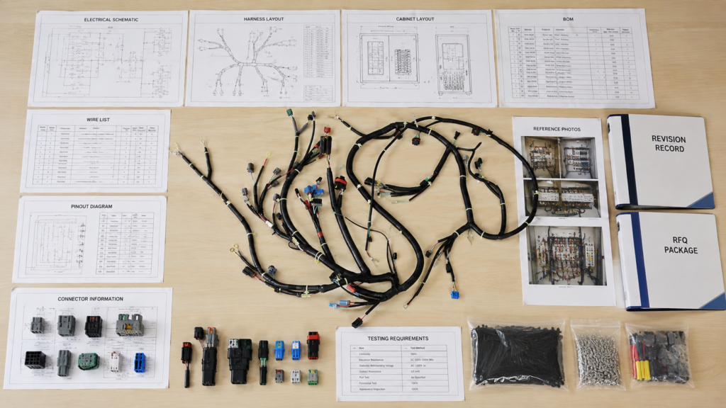
To quote a custom wire harness for an electrical cabinet accurately, a manufacturer needs the latest schematic or harness drawing, BOM, connector and terminal part numbers, pinout, wire gauge, lengths, branch locations, labels, cabinet routing constraints, operating environment, target quantity, testing requirements, packaging plan and delivery destination. Missing details force assumptions that can change price, sample timing and production feasibility.
The goal is not to overwhelm a manufacturer with every document your company has ever created. The goal is to provide one controlled package that explains what must connect, what the harness must physically look like, where it will be installed, how it will be inspected and how many units are required. A harness can pass continuity testing on a workbench and still fail inside the cabinet because one branch is 80 mm too short. Accurate quotation begins by closing that gap before the first wire is cut.
What Files Should You Send?
Schematics and Harness Drawings
An electrical schematic explains circuit logic. It may show that a PLC output connects to a relay coil, that a sensor feeds an input module, or that a power supply distributes voltage through a terminal block. This information is essential, but it often does not describe the physical harness that must be manufactured. Wire length, branch geometry, connector direction, label position, protective covering and installation clearance may be missing entirely.
A harness drawing translates the circuit into manufacturing instructions. It should identify individual conductors, branch points, overall dimensions, connector references, terminal types, coverings, labels, splices, tolerances and measuring points. When a harness has several branches, the drawing should show where each branch begins and how its length is measured. This prevents one supplier from measuring from the connector face while another measures from the wire exit.
The cabinet layout adds the physical context. It shows where PLC modules, relays, breakers, power supplies, terminal blocks, switches, HMI units, fans and other devices are installed. It also helps the manufacturer understand the intended cable-duct route, available bend space, door movement and maintenance access. A distance that appears to be 400 mm on a flat schematic may become 650 mm after the wire follows the actual cabinet route.
For a simple point-to-point assembly, a controlled harness drawing may be enough. For a branched control cabinet harness, the most reliable RFQ package usually combines the electrical schematic, physical harness drawing and cabinet layout. These documents answer three different questions: what must connect, what must be manufactured and whether the finished assembly will fit the real cabinet.
BOM and Part Numbers
The bill of materials should identify each component precisely. Descriptions such as “four-pin plug,” “red control wire” or “ring terminal” are too broad for a reliable quotation. Two similar-looking connector housings may use different contacts, locking devices, seals, wire ranges, crimp tooling or mating parts. A quotation based on the wrong contact system can be inaccurate even when the general connector family appears correct.
A useful BOM normally includes the component manufacturer, complete part number, description, quantity per harness, approved substitute status and applicable revision. Connector housings, terminals, seals, backshells, wedge locks, sleeves, tubing, heat shrink, labels and mounting accessories should be listed separately when they are purchased or processed separately. Wire should be defined by gauge, color, conductor structure and applicable insulation requirement rather than by color alone.
The BOM should also distinguish between customer-supplied and manufacturer-supplied materials. Customer-supplied parts may reduce the direct purchasing scope, but they create additional questions about incoming inspection, shortage allowance, storage, rejected components and replacement responsibility. These conditions should be discussed before the quotation is treated as final.
Approved alternatives can reduce sourcing risk, but they should be controlled. A lower-cost connector is not automatically interchangeable with the specified part. Mating dimensions, locking design, terminal compatibility, contact plating, current rating and tooling may differ. When alternatives are allowed, the quotation should clearly identify whether they are already approved or still require customer engineering confirmation.
Samples and Marked Photos
Not every project begins with complete drawings. Supplier-transfer projects, replacement harnesses, prototype cabinets and older machines may start with an existing assembly and limited documentation. A physical sample can provide useful information about wire flexibility, connector orientation, terminal retention, sleeve coverage, branch stiffness, breakout shape and label placement.
A sample may also reveal construction details that are easy to miss in a basic drawing. These can include double-wire crimps, locally applied heat shrink, grounding leads, protective tubing or a specific service loop. The manufacturer can measure the sample, identify components and compare its construction with the available schematic or cabinet photographs.
When sending a physical sample is not practical, a structured photo set can support the first review. Useful photographs show the complete harness, both connector faces, the wire-entry side, cavity numbering, terminal details, branches, labels, coverings and the installed position inside the cabinet. Dimensions should be supplied separately because camera perspective can make lengths and component sizes appear misleading.
A sample should not become the only production authority. An old harness may contain a field repair, undocumented substitution or previous supplier deviation. Before production, the approved construction should be transferred into a controlled drawing, wire list, BOM or signed sample standard. The project team should also state which document or sample controls when two references do not match.
Revisions and File Control
Many quotation problems are caused by mismatched file revisions rather than missing files. A purchasing team may send the latest BOM while engineering sends an older pinout. A revised branch length may appear in an email but not on the drawing. The manufacturer then prices a combination of documents that was never intended to be used together.
Every RFQ package should identify the active drawing number, drawing revision, BOM revision, issue date and related engineering change record. File names such as “final,” “latest,” “new final” and “final revised” are not reliable controls unless the revision is also shown inside the document. The quotation should state which file revisions were reviewed so that future changes can be evaluated against a known baseline.
A short change summary helps the supplier focus on details that may affect material, labor or testing. For example, the summary might state that connector J3 changed, branch B increased by 80 mm, wire 17 changed from AWG 20 to AWG 18, or an additional label was added. This is especially useful when a project has already passed through several prototype revisions.
Confirmed information and open information should be separated. If a connector model, tolerance or test condition remains undecided, it should be identified as an open item rather than silently estimated. A provisional quotation based on visible assumptions is more dependable than a supposedly final quotation built on details that nobody has formally confirmed.
| Required File | Minimum Information | Quotation Value | Risk if Missing |
| Electrical schematic | Circuit connections, voltage groups and device references | Defines electrical scope | Incorrect interpretation of the circuit |
| Harness drawing | Lengths, branches, terminals, coverings and tolerances | Defines manufacturing work | Suppliers quote different constructions |
| Cabinet layout | Device positions, cable ducts, doors and routing limits | Confirms physical fit | Harness fits the drawing but not the cabinet |
| BOM | Exact part numbers, quantities and approved alternatives | Establishes material cost | Wrong connector or terminal system |
| Wire list | Origin, destination, color, AWG, length and labels | Supports assembly and testing | Missing or crossed conductors |
| Pinout | Cavity numbers, viewing direction and polarity | Defines connection accuracy | Mirrored or reversed wiring |
| Revision record | Drawing revision, BOM revision and change summary | Prevents obsolete quotation data | Price is based on old specifications |
| Sample or photos | Existing construction and installation reference | Supports incomplete-document review | Hidden details remain outside the quote |
The strongest RFQ package is not necessarily the largest package. It is the package in which the documents agree with one another, the active revision is obvious and the remaining questions are clearly listed. That gives the manufacturer a stable basis for engineering review and gives the customer a quotation that can be compared more fairly with other proposals.
Which Cabinet Details Must Be Defined?

Pinouts and Wire Mapping
Every conductor should have a clearly defined origin and destination. A practical wire list identifies the wire number, source device, source terminal, destination device, destination terminal, wire color, gauge, length, termination at both ends and label requirement. This format makes it easier to review complex circuits than relying only on a dense schematic.
Cabinet harnesses may combine PLC signals, relay circuits, sensors, actuators, power conductors, communication pairs and protective-earth wires. These circuits may require different wire gauges, colors, shielding structures or routing rules. The quotation package should make those differences visible so the manufacturer does not assume that every conductor follows the same construction.
Connector pinouts must show the viewing direction. Pin numbers can appear reversed depending on whether the connector is viewed from the mating side or the wire-entry side. Circular connectors, multi-row housings and mirrored panel connectors are common sources of error. A simple orientation symbol or connector-face drawing can prevent a costly sample correction.
Polarity, crossed pairs, shared commons, jumpers, splices, shield drains and grounding conductors should be stated directly. The supplier should also know whether the electrical test needs to identify every circuit individually or whether a basic pass-and-fail result is acceptable. This affects test programming, fixture preparation and the level of test documentation included in the price.
Lengths and Routing Paths
A wire length is useful only when its measuring points are defined. Connector-face-to-connector-face, wire-exit-to-wire-exit, terminal-center-to-terminal-center and raw cut length are different values. A supplier should not be expected to infer the intended measurement method from a single number.
For branched harnesses, the drawing should identify the main trunk, every branch, each breakout point and the measuring path. Dimensions may need to follow the centerline of the harness rather than the shortest straight-line distance. This is important when wires travel through cable ducts, around DIN rails, behind mounting plates or through enclosure openings.
Cabinet routing often adds more length than expected. Two devices may be only 400 mm apart on the front view, but the installed wire may need to travel down a vertical duct, across the lower channel and back up to the destination. A quotation based on direct distance can produce a harness that passes electrical testing but cannot be installed.
Service loops should be deliberate rather than accidental. Extra length may be needed for assembly, maintenance, component replacement or door movement. Excessive slack, however, can fill cable ducts, obstruct airflow and make the cabinet harder to inspect. The project team should define where service loops are needed and how much additional length is acceptable.
Labels and Identification
Identification is part of the functional design of a cabinet harness. Installers, commissioning engineers and maintenance technicians rely on wire numbers, terminal references and device codes to trace circuits. A correctly wired harness with outdated labels can still cause installation errors, troubleshooting delays and quality rejection.
The RFQ should define the label content, location, reading direction, material, print method and attachment method. It should also state whether every conductor needs identification at both ends and whether the labels must remain visible after the wire is placed inside a duct or connected to a covered terminal block.
Common identification includes wire numbers, PLC I/O addresses, connector names, harness part numbers, drawing revisions, cabinet positions and barcode data. Multi-harness cabinet sets may also need kit numbers or installation-sequence labels so that each assembly reaches the correct cabinet position.
The label file should follow the same revision control as the drawing and wire list. If the electrical design changes but the label file does not, the factory may produce a mechanically correct harness with incorrect identification. Label verification should therefore be included in sample approval and final inspection when it is important to the customer’s assembly process.
Space and Movement
Cabinet components are often installed close together. The harness design should consider cable-duct width, connector clearance, panel edges, bend space, removable modules, fan zones and maintenance access. A connector can be electrically correct but difficult to mate if its cable exit points toward the cabinet wall.
Door-mounted HMI units, switches, lamps, meters, fans and emergency-stop devices require particular attention. The harness must accommodate the full opening movement without being pinched, sharply bent or placed under constant tension. The drawing should define the flexible loop, clamp points, covering and exit direction needed for repeated door movement.
Power and signal circuits may require separate routes. Sensitive analog signals, communication lines, encoder cables or shielded pairs should not automatically be bundled with higher-current conductors. The cabinet layout should identify any required separation so the harness geometry, shielding and branch organization can be reviewed before quotation.
Maintenance access should also be considered. A harness may fit during initial assembly but make a relay, PLC module or terminal block difficult to replace later. Serviceability influences branch length, connector orientation, tie locations and whether parts of the harness need to remain removable.
| Cabinet Parameter | Common Project Reference | What Must Be Confirmed | Selection or Inspection Value |
| Control voltage | 24 VDC is common in automation cabinets | Actual voltage and circuit function | Supports wire and test review |
| Power circuits | Systems may include 120, 230 or 400 VAC | Regional design and load requirements | Prevents incorrect power assumptions |
| Cabinet wire range | AWG 24–10 may appear across different circuits | Engineering-approved gauge for each circuit | Affects terminals, duct fill and cost |
| Short length tolerance | Example: ±5 mm below 300 mm | Customer drawing requirement | Controls compact branches |
| Medium length tolerance | Example: ±10 mm from 300–1000 mm | Installation allowance | Balances fit and processing effort |
| Long length tolerance | Example: ±1% above 1000 mm | Maximum acceptable variation | Supports long cabinet routes |
| Label position | Often 20–50 mm from termination | Visibility after installation | Improves traceability |
| Door loop | Based on opening angle and device position | Full movement without tension | Reduces pinching and fatigue risk |
The figures above are practical RFQ references rather than universal design rules. Final wire gauges, tolerances, bend allowances and service-loop dimensions must follow the approved cabinet design, circuit load, installation method and applicable project requirements.
How Do Materials Affect the Quote?

Wires and Conductors
Wire gauge is one of the first inputs used for pricing, but AWG alone does not completely define a wire. Conductor material, strand structure, insulation material, voltage rating, temperature rating, color and applicable wire specification may also affect cost and manufacturability.
Control cabinets often contain several wire sizes. Low-current PLC signals and sensor circuits may use smaller conductors, while power supplies, motors, heaters or protective-earth circuits may require larger sizes. The customer’s electrical engineer should approve the gauge based on current, voltage drop, circuit protection, installation conditions and relevant standards.
Stranding influences flexibility and terminal compatibility. Fine-stranded wire may route more easily through compact ducts, but it can require a compatible ferrule or terminal. A contact approved for a conventional stranded conductor may not be suitable for every fine-stranded construction. The wire and terminal should therefore be reviewed as a matched system.
Color coding should agree with the schematic and customer standard. When many similar colors are used, printed wire numbers or stripe identification may be more practical than color alone. The quotation should also distinguish between individual cabinet wires and multicore cable because their materials, processing and termination methods are different.
The least expensive wire is not always the lowest-cost choice for the complete project. A wire that strips inconsistently, crimps poorly or does not match the selected terminal can increase setup time, inspection effort and production risk. Material selection should consider processing stability as well as purchase price.
Connectors and Terminals
Connector cost can vary significantly even when two parts look almost identical. The housing, terminal, seal, locking device, backshell, keying, contact plating and mating part should be confirmed before the quotation is finalized.
The RFQ should provide the connector manufacturer, series, complete part number, pin count, male or female configuration, keying, terminal part number and permitted wire range. For terminal blocks, it should identify whether the wire ends require ferrules, ring terminals, fork terminals, pin terminals or stripped ends.
Contact plating can matter in low-level signal, corrosion-sensitive or repeated-mating applications. Tin-plated contacts are common in many industrial systems, while gold plating may be specified for particular signal or reliability needs. The manufacturer should follow the approved connector system rather than choose plating from a general preference.
Availability must be checked before a price is treated as firm. Some components have long sourcing periods, high supplier package quantities, regional distribution restrictions or obsolete status. The quotation should clarify whether pricing is based on the original part, an approved equivalent, a customer-supplied component or a part that still requires sourcing confirmation.
Crimp tooling is another important factor. A new contact may require a dedicated applicator, hand tool, crimp-height setup, pull-force validation or mating test fixture. These items can affect prototype cost and production preparation even when the terminal itself has a low unit price.
Shielding and Protection
Shielding may be required for analog signals, communication circuits, encoder lines or other interference-sensitive connections. Possible structures include foil shielding, braided shielding, individual pair shielding, an overall shield or a combination of several layers.
The RFQ should define where the shield begins and ends, how it is terminated and whether grounding occurs at one end or both ends. It should also state whether the shield connects to a drain wire, connector shell, ring terminal, grounding clamp or cabinet earth point.
Shield preparation adds material and labor. Production may require removing the jacket without damaging the braid, trimming foil, separating the drain wire, folding the braid, installing heat shrink and controlling exposed dimensions. Shield continuity or resistance checks may also be part of the test plan.
Protective materials can include braided sleeving, corrugated tubing, spiral wrap, heat shrink, cable ties, lacing, grommets and edge protection. Their locations and coverage lengths should be dimensioned. A request to “add protective sleeve” is too broad because a 100 mm local section and a full-length covering create very different material and labor requirements.
Protection should match the real risk. Sleeving may reduce abrasion along a cabinet edge, while heat shrink may protect a splice or label. More covering is not automatically better because excessive stiffness can make installation harder or place additional stress on a connector.
Environment and Overmolding
A harness installed inside a cabinet is not always operating in a mild environment. Industrial enclosures may be exposed to heat, vibration, oil mist, humidity, dust, cleaning chemicals or movement. Outdoor cabinets and cabinets near process equipment can present additional material challenges.
The insulation and jacket should be selected according to those conditions. PVC is common in many general applications, while TPE, TPU, PUR, silicone, PE or XLPE may be discussed when flexibility, abrasion resistance, temperature performance, oil exposure or other properties are important. No material should be presented as suitable for every project without reviewing the operating environment.
Overmolding may be useful for connector protection, strain relief, sealing, controlled exit direction or repeatable geometry. It can also introduce tooling, color, logo, material, appearance and sample-approval requirements. Those elements need to be included in the quotation basis.
Before specifying an overmold, the project team should identify the problem it is intended to solve. A standard crimped connector with a serviceable backshell may be more appropriate for a field-repairable cabinet connection. A molded construction may be more suitable when protection, sealing or repeatability matters more than field disassembly.
| Material Area | Typical Options | Main Quotation Factors | Practical Selection Value |
| Conductor | Copper, tinned copper | Gauge, strand count and copper usage | Affects current capacity and flexibility |
| Insulation | PVC, PE, XLPE, silicone | Rating, temperature and stripping behavior | Matches electrical and environmental needs |
| Jacket | PVC, TPE, TPU, PUR | Diameter, flexibility, abrasion and oil exposure | Influences routing and durability |
| Shielding | Foil, braid, foil plus braid | Coverage, termination and drain wire | Supports interference control |
| Terminals | Ferrule, ring, fork, pin, crimp contact | Part number, plating and tooling | Determines connection reliability |
| Connector system | JST, Molex, TE, M8, M12 or custom systems | Housing, contacts, seals and availability | Controls fit and sourcing risk |
| Protection | Heat shrink, sleeve, conduit and grommet | Length, diameter and installation position | Reduces abrasion and organizes routing |
| Overmolding | PVC, TPE, TPU or approved material | Tooling, shape, color and exit direction | Adds strain relief or sealing |
Final material selection should follow the approved circuit design, connector system, installation environment and target-market requirements. Material discussions are most useful when they compare real performance needs rather than presenting one option as universally superior.
What Commercial and Quality Details Matter?

Quantity and Order Pattern
The manufacturer needs more than one quantity figure. Prototype quantity, first production order, regular order size and estimated annual demand may each produce a different cost structure. A five-piece engineering sample order carries a high proportion of drawing review, setup and test preparation, while a production order distributes those activities across more units.
Material purchasing also depends on quantity. Wire may be purchased in reels, terminals may come in applicator reels or packaged lots, and connectors may have supplier minimums that exceed the first order. A quotation based on 5,000 units cannot simply be divided to estimate the cost of 20 samples.
Customers should request separate pricing at realistic levels. A useful RFQ might ask for prototype pricing, 500-piece pricing, 1,000-piece pricing and another level that reflects the expected repeat order. Excessive quantity tiers create unnecessary work when they do not match a real purchasing plan.
Forecast information does not need to be a guaranteed order, but it helps the manufacturer understand whether the project is a one-time cabinet build or a long-term supply program. It also allows both parties to discuss how excess connector inventory, reserved materials or scheduled releases should be handled.
The final minimum order quantity depends on the structure of the project. Connector packaging, terminal reels, custom wire, shielding, labels, overmolding, tooling and packaging can all affect the practical starting quantity. A general MOQ should therefore be treated as an initial reference rather than a substitute for project review.
Testing and Acceptance
“Test every harness” is not a complete test specification. The RFQ should identify the test items, test frequency, acceptance criteria and required records. Without these details, two suppliers may quote very different levels of quality control while both describe their price as including testing.
Continuity testing is commonly used to confirm that the intended points are connected and that open circuits, crossed wires or incorrect connections are detected. Short-circuit checking verifies that circuits that should remain separate are not unintentionally connected.
Other possible checks include polarity verification, insulation resistance, hi-pot testing, terminal pull force, connector fit, dimensions, label accuracy and visual workmanship. The applicable tests depend on the circuit, voltage, connector type, application risk and customer quality requirements.
Not every test is appropriate for every assembly. A hi-pot test suitable for a power harness may be unnecessary or unsuitable for a harness connected to electronic modules. Pull-force requirements should follow the terminal, conductor size, crimp specification or customer standard rather than an arbitrary universal value.
The project should also define whether electrical testing applies to every unit and whether dimensional or destructive tests use a sampling plan. Electrical connection checks are often applied to all production harnesses when specified, while destructive crimp testing is normally performed according to an agreed process-control frequency.
Standards and Records
The customer should identify any workmanship standard, company specification, material restriction, traceability rule or documentation package required for acceptance. These requirements can influence inspection time, record keeping, labels and production controls.
Possible records include a first-article inspection, dimensional report, electrical test result, crimp-height record, pull-force data, material declaration, inspection photograph, component lot reference, packing list or supplier certificate for a specified component.
The level of documentation matters. A pass-and-fail test on the production line is different from a serialized report linked to every harness. Basic batch traceability is different from recording the lot number of every connector and terminal used in each individual assembly.
Certification language should be precise. A wire, connector, plastic material, finished harness and complete electrical cabinet can have different compliance responsibilities. A certificate for one component should not automatically be presented as certification of the complete harness or cabinet.
Confidentiality can also be part of the commercial discussion. New machine designs, proprietary wiring architecture, customer labels and unreleased product drawings may require an NDA before detailed files are shared. This should be addressed early so that engineering information can be reviewed without unnecessary delay.
Packaging and Delivery
Packaging should protect the harness and support the customer’s assembly process. It can also change material cost, labor, carton dimensions and inspection requirements. The RFQ should state whether harnesses are packed individually, in bulk, as cabinet kits or in installation sequence.
Individual packaging may be useful when labels, connector protection or SKU separation are important. Bulk packaging may reduce packaging materials but increase sorting at the customer’s facility. Cabinet-set kitting can save assembly time when one kit contains every harness required for one cabinet.
Long harnesses should be coiled without creating sharp bends or permanent deformation. Connector faces may need caps, foam, dividers or separate bags. Wire labels and harness labels should remain readable and should not be damaged by ties or packaging.
The RFQ should define the part-number label, drawing revision, barcode, quantity per bag, quantity per carton, carton mark, pallet requirement and any installation-sequence packaging. Multi-SKU projects need especially clear separation because one incorrect kit can interrupt a cabinet assembly line.
The delivery destination should be supplied during quotation. Country, warehouse type and shipping method influence carton planning, documentation and schedule discussion. Sample timing and production timing should be separated because material sourcing, tooling, testing and packaging may affect them differently.
| Commercial or Quality Item | Useful RFQ Data | Common Decision Point | Cost or Risk Impact |
| Prototype quantity | Often 1–20 units, depending on validation needs | Engineering trial or cabinet fit check | High setup cost per unit |
| Initial production | Example: 500–1,000 units | First controlled production release | Material and process validation |
| Volume pricing | Realistic repeat-order quantities | Purchasing plan | Distributes setup and purchasing costs |
| Continuity test | Commonly applied to all units when specified | Connection verification | Reduces open and miswire risk |
| Pull-force test | Agreed sampling and terminal criteria | Crimp process control | Destructive test affecting inspection plan |
| Hi-pot or insulation | Defined by circuit and project requirement | Electrical safety verification | Requires controlled voltage and method |
| Traceability | Batch, date code, lot or serial number | Quality and field-service needs | Adds label and record control |
| Packaging | Bulk, individual or cabinet kit | Customer assembly method | Changes materials and labor |
| Delivery target | Separate sample and production dates | Material and capacity planning | Affects sourcing and shipment options |
These figures are common project references rather than fixed rules. The appropriate quantities, tests, records and packaging methods should be agreed according to the harness design, application risk, customer quality system and expected production plan.
How Can You Avoid Requotes and Delays?

Declare Assumptions
Incomplete specifications do not always prevent an initial quotation, but assumptions should be visible. If the connector part number is unknown, the quotation should state which component was used for pricing. If a branch dimension is missing, the estimated length should be listed.
The same principle applies to testing, labels, packaging and material. A quotation might state that continuity testing, standard visual inspection and bulk packaging are included while special reports, custom fixtures or individual packaging remain outside the current scope.
Visible assumptions allow both parties to review the same quotation basis. Hidden assumptions create the appearance of certainty until the project reaches sampling, sourcing or production. At that point, the price changes because the original quotation never described the complete requirement.
A clarification list is useful for complex cabinet harnesses. It may include open questions about terminal selection, connector orientation, wire color, branch location, label position, shielding, test voltage, packaging or delivery quantity.
The customer should distinguish confirmed information from items still under discussion. A provisional quotation can then be issued with clear conditions and converted into final pricing when the remaining specifications are confirmed.
Review Manufacturability
Engineering review connects the customer’s electrical design with practical manufacturing. The review should compare the schematic, drawing, wire list, BOM, connector information and cabinet layout to identify inconsistencies before the sample is produced.
Typical issues include an AWG 16 wire paired with a terminal intended for a smaller conductor, a connector cavity count that does not match the pinout, an undefined shield termination or a branch that cannot reach the installed device.
Manufacturability review can also consider cutting, stripping, crimping, soldering, connector assembly, sleeving, heat shrink, labeling, test access and packaging. The goal is not to redesign the customer’s electrical system but to identify manufacturing details that need clarification.
This review is especially valuable when moving from a hand-built prototype to repeat production. A skilled technician may assemble one harness by interpreting informal notes, but stable production needs documented dimensions, confirmed components, defined tools and repeatable inspection criteria.
Cablivo can support project review from drawings, samples, BOMs, connector data and application information through sample development, specification confirmation, production preparation, testing and packaging discussion. The quotation becomes more dependable when these steps happen before material is ordered.
Approve the Sample Baseline
Sample approval should confirm more than appearance. The sample should be tested in the real cabinet or in an installation fixture that represents the actual routing, connector positions and door movement.
The customer should verify connector mating, terminal retention, pinout, polarity, wire lengths, branch locations, cable-duct fit, label readability, service loops, protective coverings and required electrical checks. A harness that looks tidy on a table may behave differently when routed through a narrow duct.
Feedback should be specific and measurable. “Increase branch B by 40 mm” is actionable. “The branch feels short” is not. Marked photographs, revised drawings and measured comments help the manufacturer create a controlled revision without guessing.
When the sample changes, the documents should change with it. The drawing, BOM, pinout, label file and approved sample should not contradict one another. The project should identify which reference controls if a discrepancy is discovered.
The approved production baseline normally includes the following items:
- Final harness drawing and active revision
- Final BOM with approved components
- Approved wire list and pinout
- Confirmed wire and protection materials
- Approved physical sample
- Approved label data
- Confirmed test plan
- Confirmed packaging specification
- Confirmed quantity and delivery plan
Production scheduling should begin after this baseline is stable enough to support material preparation, process setup and quality planning. This reduces the chance that a late drawing change will affect purchased components or prepared production documents.
Control Changes
Not every engineering change requires a new quotation, but every change should be reviewed. A color change using the same approved wire may have little impact, while a change in AWG, connector type, shielding, branch count, testing or packaging can materially change cost and timing.
The impact should be evaluated across material, tooling, labor, testing, inventory and schedule. A connector change may look minor on the drawing but require new terminals, a different crimp applicator, a revised mating fixture and replacement of previously purchased stock.
Changes made after sample approval carry more risk because material may already be ordered and work instructions may already be prepared. Revisions should therefore be issued through a controlled change notice rather than scattered comments in several email threads.
For repeat orders, the purchase order should reference the approved drawing number and revision. This prevents an old part number from being ordered against a newer design or an updated harness from being produced using an obsolete document.
| Common Requote Trigger | Initial Quotation Assumption | Likely Impact | Best Preventive Action |
| Connector model changes | Preliminary or similar connector priced | New material, tooling and sourcing time | Confirm housing, terminal and mating part |
| Wire gauge changes | Original AWG used | Higher material use and new crimp setup | Approve conductor size before sampling |
| Branch length changes | Estimated route used | More wire and possible sleeve changes | Dimension the real cabinet route |
| Pinout revision | Early wire list used | Sample modification and retesting | Freeze the pinout revision for approval |
| Shielding added | Unshielded construction quoted | New material, labor and grounding work | Define interference requirements early |
| Tighter tolerance | Standard cutting tolerance assumed | More process control and inspection | Mark critical dimensions in the RFQ |
| Additional testing | Continuity only included | Fixtures, labor and reports increase | Issue the test specification before final pricing |
| Label changes | Basic numbering included | Reprogramming and reinspection | Control labels with the drawing revision |
| Packaging changes | Bulk packaging assumed | More bags, labels, sorting and cartons | Approve packaging before production |
| Quantity changes | Volume price based on forecast | Different setup and material allocation | Request realistic separate price levels |
An accurate quotation is not simply the first price issued. It is a price based on specifications that engineering, procurement, production, quality and the manufacturer understand in the same way. That shared understanding is what allows an approved sample to move into repeat production without unnecessary surprises.
For an electrical cabinet wire harness quotation, send Cablivo the latest available schematic, harness drawing, cabinet layout, BOM, connector and terminal part numbers, pinout, wire list, required lengths, AWG, application conditions, target quantity, testing requirements, label files, packaging plan and delivery destination.
When formal files are incomplete, the project can begin with clear sample photographs, connector photographs, marked dimensions and a description of the cabinet application. The available information can be reviewed first, followed by a list of details that must be confirmed before sampling.
A well-prepared RFQ does more than produce a more accurate price. It reduces repeated clarification, helps identify sourcing risks, improves sample evaluation and creates a more stable path from drawing review to material preparation, production, testing, labeling, packaging and export delivery.
To request a custom electrical cabinet wire harness quotation, submit your drawings, BOM, sample photos, connector information and expected quantity to Cablivo for an engineering review. The next step can then be confirmed according to the completeness of the project files, component availability, required testing and production plan.



