 Skip to content


A dual RJ45 cable assembly can look straightforward in a product photo, yet the phrase may describe several completely different products. One project may require a single cable that branches into two RJ45 plugs. Another may contain two independent Ethernet channels inside one protective bundle. A third may use two panel-mounted RJ45 jacks connected to internal equipment ports. These assemblies can share a similar appearance while requiring different conductors, shielding, connectors, molds, test fixtures, and production processes.
An accurate quotation therefore begins with a clear product definition rather than a target price.
To quote a dual RJ45 cable assembly accurately, provide the cable topology, RJ45 connector types, cable category, pinout, twisted-pair allocation, shielding, cable and branch lengths, jacket material, PoE conditions, application environment, testing criteria, quantities, labels, packaging, and drawings or reference samples. Unresolved topology or wiring details normally result in a provisional estimate rather than a production-ready quotation.
A useful RFQ allows the manufacturer to understand the same product that the engineering team intends to install. It should answer how many channels are present, how every pin is routed, where each branch begins, how the connectors face, and which performance requirements apply. Without that shared definition, a cable may appear correct during a visual review while failing inside the actual system.
Consider a project in which the customer expects two independent Gigabit Ethernet connections, but the initial inquiry only says “one RJ45 to two RJ45.” A supplier may interpret this as a passive pair-sharing cable, while the customer expects two complete four-pair channels. Both interpretations can produce a Y-shaped cable, but only one can serve the intended equipment. The difference is not a small quotation adjustment. It changes the complete electrical and mechanical construction.
| RFQ category | Information to provide | Effect on quotation and production |
| Product topology | Connector arrangement, branches, channels, and routing | Defines the basic cable architecture |
| RJ45 interfaces | Plug or jack, shielding, angle, latch, boot, and mounting | Determines connector sourcing and assembly method |
| Cable performance | Cable category, target data rate, and application | Influences pair construction, cable type, and testing |
| Pinout | T568A, T568B, crossover, or custom mapping | Prevents incorrect wiring assumptions |
| Dimensions | Overall length, trunk length, branch lengths, and tolerance | Determines material consumption and dimensional control |
| Materials | AWG, conductor, shielding, jacket, color, and flexibility | Affects cost, durability, and connector compatibility |
| Application | Equipment, movement, interference, and installation environment | Guides material and structural selection |
| Testing | Wire map, continuity, shield, fit, transmission, and inspection | Defines fixtures, inspection time, and documentation |
| Quantity | Samples, pilot order, production volume, and forecast | Supports material purchasing and price breaks |
| Finishing | Overmolding, labels, packaging, and connector protection | Adds process, tooling, and export requirements |
What Does “Dual RJ45” Mean?
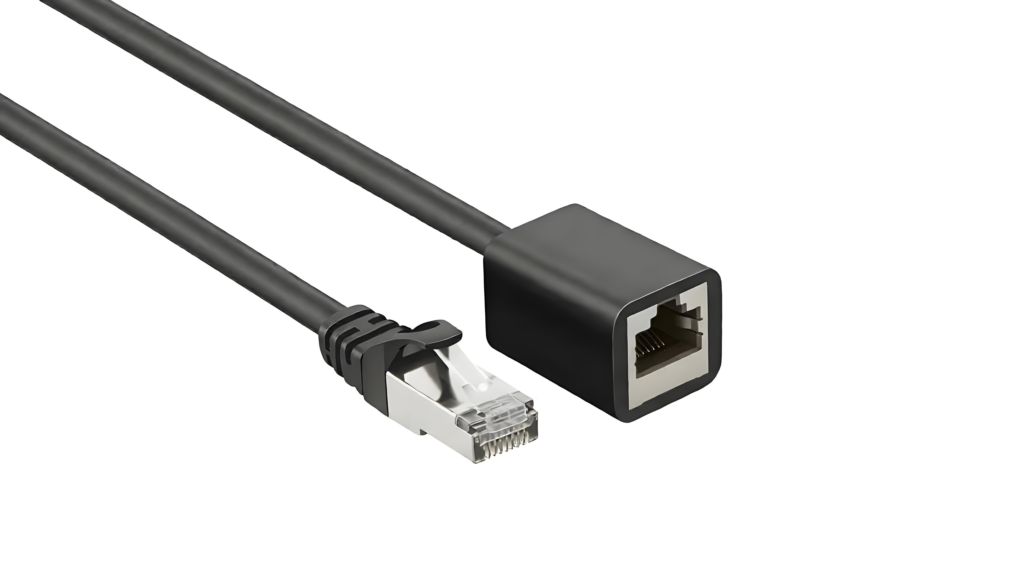
Cable Topology
The first drawing should explain what the finished assembly physically looks like. It should identify every connector, cable section, branch point, and mounting feature rather than relying only on terms such as splitter, Y-cable, dual port, or adapter. These names are used differently across network, telecom, automation, and equipment-manufacturing projects, so they do not provide enough information for a final quotation.
A practical topology drawing can label the connectors as A, B, C, and D, while cable sections are identified as L1, L2, and L3. The document should show whether there is one main trunk, two separate cables, one shared outer sleeve, a molded Y-junction, a panel plate, or an adapter enclosure. Even a simple hand sketch can be useful if every interface and dimension is clearly marked.
The word “dual” should also be defined. It may mean two RJ45 connectors, two physical branches, two network channels, or two ports mounted beside each other. Those descriptions may overlap, but they do not always lead to the same wiring or cable structure. Clarifying this point at the beginning prevents a standard branch cable from being quoted for a project that actually requires two complete Ethernet channels.
| Dual RJ45 description | Typical structure | Main confirmation point | Common project use |
| RJ45 to dual RJ45 | One trunk branching into two RJ45 connectors | Shared conductors or independent pair sets | Equipment adapters and custom interfaces |
| Dual RJ45 to dual RJ45 | Two complete cable channels | Shared jacket, sleeve, or separate cables | Control cabinets and communication systems |
| Dual-port panel assembly | Two panel-mounted jacks with internal tails | Cutout, mounting holes, panel thickness, and rear connection | Industrial panels and network cabinets |
| Dual RJ45 harness | Two cables tied or sleeved together | Bundle method, channel identification, and routing | Automation equipment and multi-port devices |
| Non-RJ45 to dual RJ45 | Proprietary connector breaking out to two RJ45 ends | Complete pin-to-pin mapping | Test systems and telecom equipment |
| Passive pair-sharing cable | Selected pairs divided between two outputs | Supported speed, device architecture, and active pins | Legacy or purpose-built systems |
Independent Channels
The two RJ45 interfaces may represent two fully independent channels, partially shared conductors, or a special wiring arrangement designed for one specific piece of equipment. The quotation should state whether both ports operate at the same time and whether each port requires a complete four-pair Ethernet path.
A fully independent Gigabit Ethernet channel normally needs four correctly maintained twisted pairs. Two independent channels therefore cannot be created simply by dividing one ordinary four-pair cable into two branches. The finished product may require two complete cable cores, a custom multi-pair construction, or two separate Ethernet cables held together by a sleeve, braid, or molded transition.
Some systems use only selected pairs, especially in legacy equipment or proprietary interfaces. That does not automatically make the same cable suitable for Gigabit Ethernet, higher-speed transmission, or four-pair PoE. The customer should identify the connected devices, required data rate, active contacts, and whether simultaneous operation is expected.
Clear RFQ language removes uncertainty. A statement such as “Ports B and C are independent channels and operate simultaneously” is much more useful than “one input with two outputs.” Where conductors are intentionally divided, the RFQ should specify exactly which source pins connect to each output and mark the remaining contacts as unused.
Splitter or Harness
A passive cable assembly should not be assumed to perform the work of an active Ethernet switch. A switch receives and directs network traffic through electronic circuitry, while a passive cable only connects conductors according to a fixed wiring map. It cannot create two unrestricted network connections from one standard Ethernet port unless the equipment and cabling architecture were specifically designed for that arrangement.
A harness describes the physical organization of cables rather than their signal function. Two complete Ethernet cables may be bundled into one assembly and shaped like a Y-cable, but they remain electrically independent. Another Y-shaped product may divide selected conductors from one source connector between two destinations. The exterior appearance alone cannot reveal which design is present.
For quotation and sample development, the safest document package contains both a mechanical drawing and an electrical table. The mechanical drawing shows the branch point, connector positions, and cable routing. The wiring table shows the destination of every pin. Contacts that are intentionally unused should be marked as “NC” or “open by design,” because an empty cell may otherwise be treated as missing information.
This distinction is particularly important when RJ45-shaped interfaces are used for industrial control, test equipment, telecom systems, sensors, or proprietary data links. An RJ45 connector does not guarantee that the wiring follows a standard Ethernet arrangement.
Connector Orientation
Connector orientation can make an otherwise correct sample impossible to install. RJ45 drawings should identify the latch side, contact side, mating face, cable-entry side, and Pin 1 position. The viewing direction should be written directly on the drawing because a pin layout viewed from the mating face appears reversed when viewed from the termination side.
Right-angle plugs, side-exit boots, and panel-mount jacks require even more detail. The customer should show whether the cable exits upward, downward, left, or right when the connector latch faces a defined direction. For dual-port panel assemblies, the drawing should include port spacing, mounting-hole locations, panel thickness, screw direction, connector depth, and available rear clearance.
Photographs are useful for showing appearance, but they should not replace a numbered connector view. A reliable RFQ normally combines photos with a part number, datasheet, sample, or drawing. When a physical reference sample is provided, the customer should also identify which features must remain identical and which may be changed for cost, availability, or installation improvement.
Which Electrical Details Are Required?

Cable Category
Cable category should be selected according to the actual application rather than treated as a promotional label. Cat5e, Cat6, and Cat6A assemblies may use similar RJ45-style connectors, yet their cable construction, pair control, shielding, diameter, connector compatibility, and performance expectations can differ considerably.
The RFQ should state the target network application or data rate, not only the requested category name. A short internal cable used for basic equipment communication has different design priorities from a longer cable expected to support higher-speed transmission through an electrically noisy industrial environment. Cable length, branch construction, panel interfaces, and termination quality can all affect the finished assembly.
Higher category language should not be applied automatically to a custom branch or adapter. A cable may use category-rated raw cable while the finished assembly includes a nonstandard junction, unusual connector, or pair-sharing arrangement that requires separate performance review. The proposed test method should therefore be discussed together with the cable category.
Cablivo’s product facts identify cable category, RJ45 type, shielding, jacket material, cable length, labeling, packaging, application environment, and testing as important network-cable customization points. They also state that Cat5e, Cat6, Cat6A, Cat7, and Cat8 descriptions must be confirmed against the real product and customer requirements.
| Cable category | Common project position | Construction considerations | Suitable quotation discussion |
| Cat5e | Basic Ethernet, control systems, and legacy devices | Four-pair structure, conductor size, and pair maintenance | Data rate, length, and active pair use |
| Cat6 | Gigabit equipment and industrial communication | Pair separation, connector quality, and termination control | Application speed and test expectation |
| Cat6A | Higher-performance and interference-sensitive systems | Larger diameter, shielding, bend radius, and compatible plugs | Routing space, shielding, and test configuration |
| Cat7-related design | Shielded proprietary or industrial systems | Individual pair shielding and connector-system review | Exact interface and customer acceptance method |
| Cat8 | Short, high-performance network links | Heavy shielding, limited routing flexibility, and test compatibility | Channel length and connector system |
| Custom signal cable | Equipment-specific communication through RJ45 interfaces | Customer-defined pairs, impedance, shield, and pinout | Device-level validation and dedicated fixture |
Pinout and Pairing
A useful pinout shows more than simple point-to-point continuity. It should preserve the relationship between conductors that form each twisted pair. This matters because a cable can connect Pin 1 to Pin 1 and Pin 2 to Pin 2 while still using conductors from different physical pairs. The cable may appear correct during a basic continuity check but experience crosstalk or unstable network performance.
A standard Ethernet assembly may use T568A or T568B. A dual RJ45 assembly may instead use a different custom mapping for each branch. Connector B and Connector C should therefore have separate mapping tables rather than one combined note that leaves the branch destination unclear.
The wiring document should identify the connector name, source pin, destination pin, conductor color, pair number, shield connection, and unused contacts. Where the customer uses nonstandard colors, the functional pair relationship should still be shown. A physical sample can help, but existing wire colors should not be treated as proof of the electrical design because previous suppliers may have used custom colors or internal transitions.
For replacement projects, the existing cable can be tested and reviewed, but the final production pinout should still be documented. Relying only on an old sample creates unnecessary risk if the sample is damaged, incorrectly repaired, or not representative of the latest equipment revision.
Shielding and Grounding
The word “shielded” does not fully define a cable structure. The RFQ should state whether the cable uses overall foil, braided shielding, individual pair foil, a drain wire, or a combined shield. For a dual-channel assembly, each cable core may have its own shield, both channels may share an outer braid, or the design may use separate shields plus one overall protective layer.
The connector shells and grounding path also need to be defined. A shielded RJ45 plug may connect the cable shield to the metal shell, but the customer should still state whether shell continuity is required between both ends and whether the two channels share a common ground path. Grounding decisions should follow the equipment design and electromagnetic compatibility strategy rather than being selected by habit.
Application details help determine the appropriate structure. Cables installed near motors, variable-frequency drives, relays, high-current wiring, or radio equipment may require a different shielding discussion from cables inside an office device. The manufacturer should review the proposed cable against the installation environment instead of automatically adding the most complex shield.
Cablivo’s documented manufacturing scope includes foil wrapping and braided shielding for network, communication, signal, and industrial cable projects where interference control or structural protection needs to be discussed.
PoE Requirements
A quotation should not describe the product only as “PoE compatible.” The customer should identify the PoE system used by the connected equipment, whether one or both RJ45 channels carry power, how many pairs are energized, and whether the cable will be installed alone or in a larger bundle.
PoE can influence conductor size, conductor resistance, connector contacts, cable length, temperature rise, and the suitability of a pair-sharing design. A cable that divides pairs between two outputs may not support a system that requires all four pairs for combined data and power delivery. That limitation should be discovered during engineering review rather than during equipment commissioning.
The connected powered device, power sourcing equipment, ambient temperature, cable bundle size, and expected operating time should be described where they are relevant. These details are especially useful for long cables, compact bundles, enclosed equipment, and higher-power applications.
| PoE consideration | Information to provide | Engineering impact |
| Equipment architecture | Power source and powered-device models | Confirms system expectations |
| Pair use | Two-pair or four-pair power delivery | Determines whether pair sharing is possible |
| Channel use | Power on one or both RJ45 channels | Affects conductor count and thermal review |
| Cable length | Length of every powered section | Influences resistance and voltage drop |
| Conductor size | Required or proposed AWG | Affects resistance, flexibility, and connector fit |
| Installation | Single cable, bundle, enclosure, or open routing | Influences heat dissipation |
| Ambient environment | Expected temperature and ventilation | Supports material and thermal review |
| Validation | Device test, current check, or customer-defined procedure | Defines sample and production acceptance |
What Mechanical Specs Affect Price?

Connector Construction
“RJ45 male” or “RJ45 female” is not a complete connector definition. A male plug may be shielded or unshielded, straight or angled, booted or unbooted, and designed for a specific cable diameter, conductor type, or category. A female interface may be an inline jack, panel-mount coupler, bulkhead receptacle, PCB jack, or sealed industrial connector.
The plug contacts must suit the conductor construction. A connector designed for one conductor diameter or insulation size may not terminate reliably on another cable. Large shielded cables may also require plugs and boots with larger entry openings than standard patch-cable components.
Where a fixed connector is required, the RFQ should include the complete part number, datasheet, and mating interface. If equivalent options are acceptable, the customer should identify the features that cannot change, such as mounting dimensions, latch position, shielding, cable-exit direction, color, mating depth, or outer shape.
Connector availability also affects the quotation. A customer-nominated imported component, obsolete jack, or low-volume specialized plug may have different minimum purchase quantities and lead-time conditions from a widely available alternative. Substitutions should be reviewed and approved rather than made silently.
| Connector feature | Common options | Quotation impact |
| Interface | Male plug, female jack, coupler, or panel mount | Changes component cost and process |
| Shielding | Plastic unshielded or metal shielded | Adds shield termination and inspection |
| Cable exit | Straight, right-angle, or side-exit | May require specialized connector or mold |
| Boot | Standard, slim, snagless, or custom molded | Changes strain relief and tooling |
| Mounting | Free-hanging, screw-mount, threaded, or flange | Adds hardware and dimensional control |
| Environmental design | Standard indoor or sealed structure | Adds gaskets, molding, and validation |
| Contact compatibility | Solid, stranded, or specific AWG range | Determines termination reliability |
| Appearance | Standard color, custom color, or molded mark | May require color matching or new tooling |
Length and Branch Geometry
Every cable section should have its own dimension, tolerance, and measurement reference. A Y-shaped dual RJ45 assembly normally requires the main trunk length, Branch B length, Branch C length, and the position of the split point. If the branches are unequal, the drawing should show each dimension separately.
The measurement method should also be defined. One drawing may measure from connector mating face to mating face, while another measures only the exposed cable between molded bodies. The difference can be significant in short assemblies because the connector body and boot occupy a large portion of the total length.
Tolerance should match the equipment requirement. Excessively tight tolerances can add inspection and cutting control without improving installation, while loose tolerances may create routing or strain problems. The customer should provide enclosure dimensions, port spacing, and any areas where excess cable cannot be stored.
Branch direction and geometry also influence the production method. Two parallel tails behave differently from branches that exit in opposite directions. A fixed molded junction may control the branch angle, while heat-shrink or sleeve transitions may allow more movement. Panel-mounted cables should include the available bend space behind the panel so that the connector depth and minimum routing radius can be reviewed.
Jacket and Flexibility
The jacket material affects flexibility, abrasion resistance, temperature behavior, oil or chemical exposure, appearance, and processing. PVC is widely used for general-purpose applications, while TPE, TPU, PUR, PE, and other materials may be discussed for different handling or environmental conditions. The final grade should be selected against the actual equipment and target market.
A stationary cable inside a protected cabinet does not need the same construction as a cable attached to a moving mechanism. A handheld product may prioritize flexibility and surface feel, while an industrial machine may require abrasion resistance, oil resistance, or a more robust outer jacket.
Cable diameter affects the connector, boot, bend radius, panel clearance, packaging, and overmold design. Two complete Ethernet cores placed inside a common outer structure can create a substantially larger assembly than a standard patch cord. The customer should therefore provide routing space and connector-clearance information instead of selecting the cable only from electrical requirements.
Flexibility should be described through the real movement pattern. Terms such as stationary, occasional movement, repeated bending, continuous flex, drag-chain routing, or frequent handling are more useful than simply requesting a “soft cable.” A very soft material may improve handling but reduce abrasion performance or complicate dimensional control.
Overmolding and Identification
Overmolding should serve a defined function. It may strengthen the cable exit, protect a connector, create a controlled Y-junction, support sealing, improve handling, or provide a repeatable branded appearance. Treating it only as a decorative feature can lead to unnecessary tooling and material choices.
A molded branch drawing should show the body length, width, thickness, entry direction, exit angle, surface finish, color, and any logo or marking area. The proposed overmold material must also be compatible with the cable jacket and the required operating environment.
Tooling cost varies with the shape, insert arrangement, number of cable entries, sealing details, production volume, and expected sample revisions. A simple strain-relief boot and a multi-part sealed panel junction do not require the same engineering effort.
Identification is particularly valuable when the two RJ45 branches look identical but connect to different equipment ports. Port A and Port B may be distinguished through heat-shrink markers, printed sleeves, color-coded boots, wraparound labels, barcodes, or serial numbers. The RFQ should define whether the labels are fixed, sequential, serialized, or linked to specific cartons and SKUs.
| Identification method | Suitable use | Main value | Information to confirm |
| Printed cable marking | Repeated product or cable information | Permanent identification without an added label | Print position, content, and repeat interval |
| Heat-shrink marker | Port and branch identification | Secure and visually clean | Sleeve size, location, and text |
| Wraparound label | Barcode, SKU, or warning information | Holds more detailed data | Adhesive, print quality, and readability |
| Color-coded boot | Fast channel recognition | Reduces installation errors | Color standard and material availability |
| Serialized label | Traceability programs | Links the cable to inspection or system records | Number source and sequence format |
| Molded symbol or logo | Long-term product identity | Durable appearance | Tooling, artwork, and authorization |
| Connector dust cap | Transport and storage protection | Reduces contact and latch damage | Cap style and packing method |
Which Testing and Order Details Matter?

Electrical Checks
Continuity and wire-map testing form the foundation of most dual RJ45 cable inspection plans. The fixture should confirm that every required contact reaches the correct destination and that unintended connections do not exist. In a dual-output design, the test system must distinguish Connector B from Connector C rather than confirming only that a source contact connects somewhere.
A standard Ethernet wire-map check may identify open circuits, shorts, reversed pairs, crossed pairs, and split pairs. A custom pinout fixture should be programmed against the approved wiring table so that nonstandard connections are treated as intentional rather than automatically rejected.
Shield continuity can also be checked where the assembly includes shielded cable and metal connector shells. Connector fit, latch operation, cable length, label position, and visual workmanship may be included in the regular production inspection plan.
Finished assemblies are often subjected to complete continuity or wire-map inspection because one incorrect connection can make the cable unusable. Reliability tests such as bending, pull force, insertion life, temperature, humidity, or corrosion exposure are normally selected according to the application and performed through an agreed sampling plan rather than applied to every unit.
Cablivo’s testing boundaries include continuity, wire sequence, pinout, connector fit, pull force, bending, insertion life, insulation, appearance, labeling, packaging, and pre-shipment inspection. The applicable items depend on the product type, environment, and customer requirements.
| Test item | Main purpose | Typical application |
| Continuity | Confirms required electrical paths | Most cable assemblies |
| Short-circuit check | Detects unintended contact connections | Multi-pin and custom pinout products |
| Wire map | Confirms correct pin and branch destination | Standard and custom Ethernet assemblies |
| Split-pair check | Confirms that twisted-pair relationships are maintained | Data transmission cables |
| Shield continuity | Confirms the defined shield path | Shielded RJ45 assemblies |
| Connector-fit check | Confirms mating, latch, and panel installation | New connector and sample projects |
| Length inspection | Confirms each cable section and branch dimension | Equipment-specific harnesses |
| Appearance inspection | Reviews molding, jacket, labels, and workmanship | Sample approval and production |
| Packaging inspection | Confirms protection, SKU, and carton information | Export and private-label orders |
Transmission Testing
The phrase “network tested” should be translated into a measurable acceptance requirement. A functional connection test may only confirm that two devices establish a link. A qualification test may determine whether the cable supports a specified application level. A category-related performance test may evaluate several transmission parameters under a defined test configuration.
These forms of testing are not interchangeable. A cable that successfully connects two devices during a short bench test may not satisfy the same performance expectations as an assembly tested against defined cabling limits. Conversely, a proprietary short equipment cable may not fit a standard permanent-link or channel test arrangement.
The RFQ should identify the required data application, cable category, test setup, acceptance limit, equipment preference, reporting format, and sampling rate. Where the customer requires individual test records, the quotation should also account for report generation, serial-number control, and data storage.
Custom branches, panel interfaces, and mixed connector systems may require a dedicated validation method. The customer and manufacturer should agree on a realistic acceptance process before sample approval, particularly when the assembly contains nonstandard junctions or uses RJ45 connectors for proprietary signals rather than standard Ethernet.
Reliability and Compliance
Reliability testing should reflect the real use condition. A stationary cable inside an enclosure may mainly require wiring accuracy, connector fit, dimensional inspection, and packaging protection. A cable on a moving machine may need bending or swing evaluation. An outdoor or corrosive environment may require discussion of jacket durability, temperature, humidity, sealing, or corrosion resistance for exposed metal components.
Pull-force testing can help evaluate terminal retention, connector attachment, cable anchoring, or an overmolded joint. Connector insertion and withdrawal testing may be useful where the product is frequently disconnected. Insulation or voltage-related testing may apply to certain mixed-signal or industrial assemblies, but it should not be added automatically to every RJ45 cable.
Compliance requirements should identify the destination market, product category, customer standard, and exact document needed. Supplier declarations, restricted-substance documents, cable markings, material records, flame-performance requirements, or external laboratory reports may affect material selection and sourcing.
A responsible quotation distinguishes between documents already available from material suppliers, records generated during production, and new testing that requires additional equipment or third-party services. This prevents a general compliance request from being interpreted as a promise that every possible certificate is already included.
Quantity and Packaging
Unit price depends on more than the total number of cables. The manufacturer also needs to understand how the project moves from samples to pilot production, how the order will be released, how many SKUs are involved, and how the finished products must be packed and delivered.
The RFQ should separate engineering samples, pilot quantity, initial production, forecast demand, and requested price-break levels. A project with a small sample requirement and a realistic annual forecast can be evaluated differently from a one-time inquiry with no confirmed production plan.
Cablivo’s standard MOQ starts from 500 pieces for many custom cable projects, while the final MOQ depends on the connector, cable construction, materials, overmolding, tooling, packaging, and order quantity.
Packaging instructions should define winding diameter, cable tie, dust cap, connector protection, individual bag, barcode, label position, quantity per carton, carton mark, pallet requirement, and multi-SKU separation. RJ45 latches, panel hardware, and molded junctions can be damaged if the cable is wound too tightly or compressed inside an unsuitable carton.
| Order information | Procurement and production value | Example input |
| Engineering samples | Determines sample material and fixture needs | Required sample quantity |
| Pilot order | Supports equipment and installation validation | Small controlled production batch |
| Initial production | Establishes the first manufacturing plan | Confirmed first-order quantity |
| Price breaks | Shows how material and setup costs change | Several target quantity levels |
| Annual forecast | Supports component and capacity planning | Estimated yearly demand |
| Release schedule | Affects material storage and shipment planning | One delivery or scheduled releases |
| SKU count | Changes labels, inspection, and packing | One design or several variants |
| Destination | Influences carton, documents, and shipping preparation | Country, warehouse, or fulfillment location |
| Packaging format | Defines protection and handling requirements | Bulk, individual, branded, or retail-ready |
How Do You Submit a Quote-Ready RFQ?

RFQ Documents
A dimensioned mechanical drawing is usually the most efficient starting point. It should show the connector arrangement, cable lengths, branch point, connector orientation, tolerances, labels, panel features, and any molded structures. Each connector and cable section should have a unique reference so that later discussions remain clear.
The electrical information should be placed in a separate pinout or wiring table. Every pin should be shown as connected, unused, shielded, grounded, or reserved. A note buried in a long email is harder to control than a numbered table that becomes part of the approved project file.
A BOM is useful when the customer has nominated connector brands, jacket materials, sleeves, labels, or accessories. Connector datasheets and mating-part information help confirm availability and compatibility. Sample photos should show the front, rear, latch side, contact side, and cable exit, while a physical sample can be used to compare dimensions, flexibility, fit, and appearance.
Drawing revisions and file names should remain controlled. When a pinout, dimension, material, or label changes, the revised document should receive a new version number. This reduces the risk of quoting one revision, sampling another, and preparing production from an outdated file.
| RFQ item | Minimum useful content | Project value |
| Topology drawing | Connector arrangement and branch structure | Prevents product-definition errors |
| Mechanical drawing | Lengths, tolerances, direction, and dimensions | Confirms fit and material usage |
| Pinout table | Source pin, destination, pair, and wire color | Prevents wiring and pair mistakes |
| BOM | Cable, connectors, boots, labels, and accessories | Supports accurate material costing |
| Connector datasheet | Part number, mating component, and dimensions | Confirms sourcing and compatibility |
| Sample photos | Front, rear, latch, contacts, and cable exit | Clarifies appearance and orientation |
| Physical sample | Existing or approved reference cable | Supports comparison and dimensional review |
| Application summary | Equipment, data function, PoE, environment, and movement | Guides structure and material selection |
| Test specification | Test items, acceptance limits, reports, and sampling | Defines quality requirements |
| Packaging file | Label, barcode, bag, carton, and artwork | Supports complete delivery planning |
| Quantity forecast | Samples, pilot, production, and annual demand | Enables realistic MOQ and price breaks |
Cablivo’s project information guidance asks customers to provide drawings, sample photos, BOMs, connector models, cable length, AWG, pinout, wire sequence, application, target quantity, testing requirements, packaging requirements, and shipping destination. Clear inputs improve engineering efficiency and quotation accuracy.
Starting Without a Drawing
Not every project begins with complete engineering documentation. A replacement-cable inquiry may start with a damaged sample. A product team may only have a connector photo and an early enclosure layout. A procurement team may have an old supplier code without the original technical drawing.
In those situations, the customer should provide photographs from several angles, connector close-ups, approximate dimensions, equipment information, known pinout details, data or power function, target quantity, and the intended country of use. A ruler or scale placed beside the sample can help with the preliminary review, although final dimensions should still be confirmed through a drawing.
Each detail should be marked as confirmed, reference only, or pending verification. This makes the project status visible and prevents an estimated dimension from being treated as a production requirement.
A preliminary price may include conditions where specifications remain unresolved. For example, the quotation may be based on a standard shielded RJ45 connector pending final confirmation of the customer-nominated part. Once the connector, drawing, sample, and test requirements are approved, the quotation can be updated into a production-ready version.
The company’s engineering-content boundaries allow early review based on sample photos, connector photos, cable length, application information, and target quantity where complete drawings are unavailable. Final specifications still need confirmation before sampling and production.
Engineering Review
Engineering review should address both manufacturing feasibility and application risk. The manufacturer checks whether the connector suits the conductor and cable diameter, whether twisted-pair relationships are maintained, whether the shield termination is clear, and whether the branch junction can be produced consistently.
The review may also identify problems outside the assembly process. A bend radius may be too tight for the proposed cable. A right-angle connector may face the wrong direction inside the enclosure. The selected pair-sharing arrangement may conflict with the required data rate or PoE system. A panel connector may require more rear clearance than the equipment provides.
A practical review should leave the project team with two clear records: confirmed specifications and open questions. Each open point should have an owner and a required decision before sampling.
Common review items include:
- Cable topology and channel relationship
- RJ45 connector model and mating interface
- Cable category and required data application
- Pinout and twisted-pair allocation
- Shielding, grounding, and drain-wire treatment
- PoE and conductor requirements
- Jacket material, cable diameter, and flexibility
- Lengths, tolerances, and branch geometry
- Panel mounting and connector orientation
- Overmolding, strain relief, and tooling
- Identification, labels, and barcode requirements
- Test method and acceptance records
- Packaging and connector protection
- Component availability and approved alternatives
If a nominated component is unavailable, the alternative should be compared for dimensions, mating performance, cable compatibility, shielding, mounting, appearance, and availability. A substitution should be approved through the project documents rather than introduced during production.
Sample to Production
Sampling converts the written requirements into a physical reference. The sample should be checked inside the actual equipment whenever possible because a cable can meet the drawing and still reveal routing, access, or handling problems during installation.
The sample review should cover connector fit, latch access, panel mounting, cable routing, branch length, bend radius, cable feel, channel identification, wire map, data function, PoE operation where applicable, molding appearance, labels, and packaging assumptions.
Feedback should be measurable and linked to the drawing. “Make the branch longer” should become a revised dimension. “The cable is too stiff” should lead to a defined material, diameter, or flexibility requirement. “The connector points the wrong way” should be corrected through an orientation view rather than an informal message.
Before mass production, the approved sample, final drawing, final pinout, BOM, connector source, material specification, color reference, test criteria, label artwork, packaging method, quantity, inspection requirement, and shipping destination should be locked.
These controlled documents guide purchasing, cutting, stripping, termination, soldering or crimping, molding, testing, labeling, packaging, and shipment preparation. They also reduce the risk that production follows an early quotation sketch while the customer evaluates a later sample revision.
Cablivo is the overseas-facing brand of Shenzhen Tianxiaowei Electronics Co., Ltd., a Shenzhen-based custom cable, wire harness, and cable assembly manufacturer. Its documented foundation includes 18 years of industry experience, more than 20,000 square meters of factory space, a team of over 1,500 people, and three manufacturing bases. Its project support covers requirement review, drawing review, material selection, sampling, production, testing, packaging, labeling, and shipment coordination.
For a dual RJ45 cable assembly quotation, send the topology drawing, connector photos or part numbers, pinout, cable category, shielding requirement, dimensions, application details, target quantities, testing criteria, and packaging files. The project information can then be reviewed for missing specifications, connector compatibility, sample planning, testing, and production feasibility.
A complete RFQ does more than shorten the quotation process. It reduces the chance of connector mismatch, wiring errors, incorrect pair allocation, unsuitable cable selection, unnecessary sample revisions, damaged packaging, and differences between the approved sample and mass production. It creates a controlled path from an initial product idea or existing sample to a cable assembly that can be manufactured, inspected, packed, and delivered according to the agreed project requirements.



