 Skip to content


A D-Sub cable may appear simple on a purchasing list: two connectors, one cable and a required length. Once the project reaches engineering review, however, that short description can hide dozens of decisions. Connector density, contact arrangement, pin mapping, shielding, grounding, cable exit, hardware, conductor size, testing and packaging can all change the materials, manufacturing process and final cost.
An accurate D-Sub cable assembly quote requires a controlled drawing or reference sample, exact connector and backshell specifications, a complete pinout, cable construction and length, shielding and grounding details, application conditions, testing requirements, order quantity, packaging and delivery information. The quotation should also identify unresolved assumptions and items that require approval before sampling or production.
Consider three suppliers quoting what appears to be the same “DB9 male-to-female cable.” One may price an unshielded straight-through assembly, another may include a metallized backshell and custom pinout, while the third may assume an off-the-shelf serial cable. Each price may be reasonable for its own interpretation, yet the three quotations cannot be compared fairly because they describe different products.
What Documents Should You Submit?
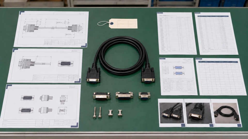
Assembly Drawing
The assembly drawing should describe the physical product clearly enough that engineering, procurement and production teams can discuss the same cable without relying on memory. It should show both connector ends, finished cable length, measurement reference points, connector orientation, backshell direction, branch dimensions, labels, heat-shrink positions, sleeves, fixing hardware and any dimensions that affect installation.
Cable length needs more definition than a single number. A dimension marked “1,000 mm” might refer to the distance between connector mating faces, between backshell exits or between the ends of the flexible cable section. Those interpretations require different material lengths and may fit the equipment differently. The drawing should identify the measurement method and an acceptable tolerance.
The connector view must also be labeled. A mating-face view and a wire-side view are mirror images, so an unclear drawing can reverse the intended pin arrangement even when every pin number appears correct. Showing the viewing direction beside the pinout reduces the risk of producing a mechanically correct cable with an electrically reversed layout.
A practical drawing does not need to look complicated, but it should have a drawing number, revision, release date and approval status. These details prevent a familiar project problem: engineering updates the connector orientation while purchasing continues requesting quotations from an older file saved under a similar name.
BOM and Part Numbers
The BOM should identify every component that affects fit, material cost, processing or quality control. Typical entries include the D-Sub connector body, contacts, cable, backshell, locking screws, cable clamp, heat-shrink tubing, protective sleeve, label, ferrule, overmold material, dust cover and packaging components.
Each part should be marked as mandatory, preferred, supplied by the customer or open to an approved alternative. Two connectors that appear nearly identical may differ in contact plating, wire range, shell finish, hardware thread, termination style or dimensional tolerance. Without sourcing rules, the manufacturer cannot know whether it should price an exact specified component or evaluate an equivalent.
Approved alternatives can be useful when a project faces long component lead times, but the characteristics that cannot change should be listed. These may include shell size, pin count, gender, mounting geometry, contact material, plating, mating dimensions, hardware and cable range. This creates controlled sourcing flexibility without allowing an undocumented substitution.
D-Sub product families are available in several termination forms, including crimp and solder-cup designs, so a connector description alone does not define the manufacturing process. Different terminations may require different contacts, tools, fixtures, inspection steps and labor.
Pinout and Sample Evidence
A pinout should be provided as a structured circuit table rather than a note such as “standard serial wiring.” The same connector pair can be wired straight through, crossed, partially populated, looped back or configured for a particular machine. A manufacturer cannot safely infer the wiring from the connector shell or the equipment category.
The table should identify the End A pin, signal name, wire color or circuit number, End B destination and any grounding or shielding note. Unused pins should be marked “NC” rather than left blank. Bridges, jumpers, shell bonds, drain wires and common returns should be shown explicitly so they are included in labor, inspection and fixture planning.
A reference sample is especially useful when an old drawing is incomplete or the project is transferring from another supplier. The sample may reveal the backshell profile, cable flexibility, locking screw type, overmold shape, label location and routing behaviour inside the equipment. Clear images of the mating face, side view, rear cable exit and complete assembly can support an initial review.
The sample still needs a written status. It might be an approved production unit, a failed cable, an obsolete version or only a visual reference. Treating every supplied sample as an approved master can reproduce a previous problem instead of solving it. The valid pinout, materials and dimensions should therefore be confirmed separately.
Revision Control
Revision control should establish one current specification and one approval route. File names such as “final,” “new final” and “latest final” do not reliably show which product should be quoted. A drawing number, revision letter or number, release date and concise change description provide a far clearer record.
Small revisions can change cost more than expected. Increasing cable length affects conductor and shielding consumption. Changing the connector may alter contact type, tooling and availability. Revising the cable exit may require another backshell. Adding a label, test or packaging requirement may introduce material, fixture or inspection time.
The quotation should state the exact drawing and BOM revision on which it is based. If the specification changes after quotation, the manufacturer can then explain whether the change affects price, tooling, material already purchased, sample timing or production planning instead of restarting the entire discussion without a clear reference.
For repeat orders, the approved sample, final drawing, confirmed BOM, connector record, material requirements, label file and packaging record should remain linked to the product. Cablivo’s documented workflow uses these records to support consistency and reduce confusion between previous and updated versions.
Which D-Sub Details Must Be Confirmed?

Density and Shell
Standard-density and high-density D-Sub connectors can use the same general shell envelope while carrying different contact arrangements. Official product examples pair a 9-position standard-density layout with a 15-position high-density layout in the E shell, a 25-position standard layout with a 44-position high-density layout in the B shell and a 50-position standard layout with a 78-position high-density layout in the D shell.
This makes a description such as “15-pin D-Sub” incomplete. It may refer to a two-row standard-density DA-15 or a three-row high-density DE-15. The two products have different mating interfaces and are not interchangeable, even though both contain fifteen contacts and may be described using similar informal language.
“DB9” is widely used in commercial conversation, but terminology alone should not control production. The safer approach is to provide the connector part number, contact count, row arrangement, mating-face image and equipment-side mating connector. That combination lets the manufacturer check the physical interface without turning the quotation process into a debate about naming conventions.
When an exact part number is unavailable, a clear front photograph with basic dimensions can support identification. The image should show the rows, contact gender, mounting ears and fixing hardware. Side photographs can reveal whether the connector is cable mounted, panel mounted or integrated into a particular backshell.
Gender and Mating Fit
Specify whether each cable end uses pins or sockets, and provide the mating connector wherever possible. The terms plug, receptacle, male and female can become confusing when different people view the connector from opposite sides. A mating-face drawing removes much of that ambiguity.
The mating reference also helps check hardware and enclosure fit. Two D-Sub connectors may have compatible contact patterns but use different screw threads, shell clearances or mounting arrangements. The assembly may connect electrically yet remain impossible to secure to the equipment panel.
Every cable end should be defined independently. A project may require D-Sub to D-Sub, D-Sub to open wire, D-Sub to a terminal block or D-Sub to another connector family. For open-wire ends, specify wire length, strip length, ferrules, terminals, labels and any grouping or sleeving requirements.
Phoenix Contact publishes D-Sub system cables in both connector-to-connector and D-Sub-to-marked-open-wire configurations. Those product distinctions illustrate how the second end and its wire preparation form part of the assembly specification, not a minor finishing detail.
Contacts and Termination
D-Sub cable connectors may use crimp contacts, solder cups or other series-specific termination methods. The selected termination affects component cost, contact procurement, tooling, assembly time, inspection and repairability. A quote based only on the connector shell may therefore leave a significant part of the production process undefined.
For crimp assemblies, the contact must match the conductor gauge, insulation diameter and connector insert. Production may require approved crimp tooling, contact insertion tools, extraction tools and pull-force checks. A change in conductor size may force a change in contact even when the external connector remains unchanged.
For solder-cup assemblies, the manufacturer must consider cup capacity, conductor preparation, insulation setback, soldering access, heat exposure and strain relief. The process can be suitable for many custom pinouts, but densely populated connectors may require more controlled routing and inspection than a lightly populated connector with only a few active circuits.
TE separates crimp D-Sub categories from other connector constructions, while NorComp offers both standard-density and high-density solder-cup cable-mount products. These official product families show that termination style is a real product-selection variable rather than a generic factory preference.
Backshell and Hardware
The backshell controls more than appearance. It supports cable retention, strain relief, shielding, exit direction, enclosure clearance and serviceability. Common choices include plastic hoods, metallized plastic hoods, metal backshells, angled entries and molded structures.
The RFQ should identify the shell size, cable entry direction, cable outer diameter, clamp range, maximum dimensions and fixing hardware. A straight-exit hood may be inexpensive but unsuitable when the cable must bend immediately behind a shallow panel. A side-entry or top-entry hood may solve the space problem but change routing and assembly cost.
Hardware should match the equipment-side connector. Examples from Amphenol include D-Sub backshells with straight, top and side cable entry and #4-40 hardware, while broader accessory ranges include plastic, metallized plastic and metal hoods, cable clamps and locking devices.
An overmolded connector can provide an integrated strain-relief shape and repeatable appearance after sample approval, but it may require tooling and is normally less serviceable than an assembled hood. The appropriate choice depends on installation, quantity, protection requirements, product life and expected field maintenance.
How Should the Cable and Pinout Be Specified?

Circuit Mapping
The pinout should identify End A, End B, pin number, signal name, wire colour or circuit number and any special routing instruction. When the second end is open wire, the table should show the destination label, terminal, strip length or preparation method rather than leaving the endpoint undefined.
Unused pins should be marked “NC.” Bridges and loopbacks should be drawn clearly. If several pins share a return, identify where the conductors join. If a drain wire connects to the shell, a contact or a separate flying lead, include that connection in the pinout rather than hiding it in a general note.
Signal names provide useful context. Labels such as encoder A+, control return, 24 VDC, analogue input or chassis shield help engineering recognise paired conductors, polarity, current-carrying circuits and grounding relationships. The manufacturer should not redesign the electrical system, but it can identify contradictions between the pinout and proposed cable structure.
Circuit population also affects price. A 25-position connector with eight active circuits requires different conductor material, routing and termination labour from a fully populated 25-conductor assembly. Quoting from shell size alone may therefore produce a price that changes once the real pin map is received.
Conductor Selection
The conductor specification should include gauge or cross-sectional area, material, stranding when relevant, insulation and circuit colour or number. The correct size depends on current, voltage drop, cable length, connector contact range, flexibility, finished diameter and installation conditions rather than a universal D-Sub rule.
Larger conductors can carry more current or reduce voltage drop, but they also increase cable diameter and stiffness. They may not fit the selected solder cup, crimp contact or backshell clamp. Using a larger size without checking the complete connector system can create a cable that is electrically conservative but mechanically difficult to assemble.
Fine stranding can improve flexibility, especially where the cable is handled frequently, but it may affect termination and cost. The contact system must accept the conductor construction, and the production process should maintain consistent wire preparation before crimping or soldering.
For mixed power-and-signal assemblies, specify each circuit group separately. A single AWG value may not suit both low-level signals and powered circuits. TE’s D-shaped connector portfolio includes special arrangements that combine signal contacts with power or coaxial cavities, demonstrating that the general D-Sub form can support substantially different internal circuit structures.
Shielding and Grounding
A shielding requirement should state both the cable construction and the termination method. Common structures include foil, braid and combined foil-plus-braid shielding. The RFQ should identify whether a drain wire is required and whether the shield connects to the connector shell, a defined pin, one end only, both ends or a separate lead.
A metal backshell does not automatically establish the intended shield path. The connection between cable shield and connector shell may be clamped, wrapped, soldered or transferred through a drain conductor. The chosen method changes materials, cable preparation, backshell selection and assembly time.
Signal ground, chassis ground, protective ground and cable shield should not be treated as interchangeable unless the equipment design defines them that way. A project with electromagnetic compatibility concerns may need a system grounding diagram because cable construction alone cannot resolve every interference problem in the installed equipment.
Phoenix Contact’s open-end D-Sub assemblies separately describe marked conductors, ferrules and a braided shield routed to another cable end. This is a useful example of how shield handling and open-wire preparation should be defined as part of the assembly rather than assumed.
Length and Jacket
The finished cable length should include clear measurement points and tolerance. For hooded assemblies, the dimension may be measured between connector faces, backshell exits or other defined datums. Branches, fan-outs and exposed-wire sections should each have their own dimensions when they affect installation.
Jacket requirements should cover material, colour, outer diameter, flexibility and the actual environment. PVC is common in many general cable constructions, while TPE, TPU, PUR, silicone, PE and other materials may be evaluated for particular handling or environmental needs. Material selection should be based on confirmed requirements and supporting documentation.
A material with higher nominal performance is not automatically the best choice. It may increase cost, diameter, stiffness or sourcing difficulty. The useful question is whether the application requires better flexibility, abrasion resistance, chemical exposure performance, temperature capability or another measurable characteristic.
Official Phoenix Contact D-Sub system-cable data shows that position count, conductor cross-section, AWG, jacket material, external diameter, cable resistance, insulation resistance and bend radius can all be controlled product characteristics. These values vary by construction, which is why a custom quote should be based on the required cable rather than copied from an unrelated standard product.
What Application and Testing Requirements Matter?

Installation Conditions
Describe the equipment, installation location, routing and available space. A cable mounted permanently inside a control cabinet faces different handling risks from a service lead that technicians connect and disconnect every day. Those differences may affect cable flexibility, backshell selection, strain relief and mechanical testing.
Installation images often reveal issues that are not obvious in a connector datasheet. A straight backshell may collide with a panel. The cable may need to bend immediately after leaving the hood. Locking screws may be difficult to reach, or the connector may need to pass through a limited opening before final assembly.
State whether the cable remains fixed, flexes occasionally, moves continuously, passes through a conduit or runs near motors and power conductors. These details influence conductor stranding, shielding, jacket, exit direction and whether a flex-related validation is relevant.
Application information also helps the manufacturer question conflicting requirements. A stiff, large-diameter cable may be electrically suitable but impossible to route through the available enclosure. Raising that problem before quotation is far less costly than discovering it after the first sample arrives.
Environmental Exposure
List the operating and storage conditions that genuinely apply. Temperature, humidity, dust, water, oil, coolant, cleaning chemicals, vibration, corrosion and outdoor exposure may affect cable material, backshell, plating, sealing, strain relief and validation.
Avoid specifying the most expensive material simply because it sounds safer. Higher-performance materials may increase diameter, stiffness, sourcing difficulty and cost without improving the installed product. Each material requirement should connect to a credible condition and, where needed, a defined acceptance method.
Corrosion concerns should identify the exposed metal parts and the desired evaluation. Moisture concerns should define whether the connector itself must be sealed or whether the cable is only exposed to occasional condensation. A general phrase such as “industrial environment” does not provide enough detail to choose a material or test.
Cablivo’s documented quality boundaries require testing and certification requirements to be confirmed according to product type, application and target market. The presence of testing equipment does not mean that every cable automatically carries every certification or receives every available test.
Electrical Inspection
Continuity and pinout verification are common checks for custom D-Sub assemblies because they can detect open circuits, shorts, crossed wires and incorrect pin mapping. A dedicated fixture or programmed cable tester can compare the finished assembly with the approved circuit record.
Further electrical testing depends on the function. Insulation resistance or Hi-Pot testing may be relevant for higher-voltage or safety-sensitive circuits. Resistance measurement may matter where cable length and conductor loss are important. Functional testing may be needed when continuity alone cannot confirm communication or equipment operation.
The RFQ should state whether inspection applies to every assembly, a defined sample or only the development stage. It should also identify test voltage, limits, duration, mating fixture and report requirements. “Full electrical testing” is too broad because different project teams may understand it in very different ways.
Where customer equipment is needed for a functional check, clarify who supplies it, how it will be protected and whether a simulator is acceptable. These details can affect fixture development, sample scheduling and production cycle time.
Mechanical and Quality Checks
Mechanical inspection may include connector fit, dimensional checks, locking screw engagement, cable-retention pull force, crimp pull force, bending, insertion and withdrawal, overmold appearance and strain-relief evaluation. The useful tests are those connected to credible use conditions.
A pull test without a defined direction or limit can produce a number without a meaningful acceptance decision. A flex test without bend radius, angle, load and cycle count is similarly incomplete. Test methods need enough detail that engineering, production and quality teams evaluate the same requirement.
Quality planning should also include labels and packaging. An electrically correct cable can still create field problems if the label is wrong, a connector contact is bent during transport or several pinout versions are mixed in one carton. Multi-model programs need clear segregation, barcode and packing controls.
Cablivo’s available checks may include continuity, pinout, connector fit, insulation, pull force, bending, visual, label and packaging inspection when relevant. Specific voltages, forces, cycles, reports and certification claims must be confirmed for the project rather than assumed.
How Do Commercial Requirements Affect the Quote?

Quantity and Cost Basis
Separate the engineering sample quantity from the production quantity. Samples often require engineering review, small-quantity sourcing, manual setup, fixture preparation and closer inspection. Those costs cannot always be distributed in the same way as a larger production order.
Provide the expected initial order and realistic price-break quantities. An annual forecast can help the manufacturer discuss component sourcing, material planning, packaging and repeat production, but the forecast should be identified as estimated or committed.
A quotation should explain whether the unit price includes one-time setup, test fixtures, samples, molds, special labels or packaging. Without that separation, a low unit price may appear attractive while important project costs remain outside the quotation.
For many Cablivo custom cable projects, the starting MOQ is 500 pieces, while the final requirement depends on connector type, cable structure, materials, overmolding, tooling, packaging and order quantity. The actual MOQ for a D-Sub project should therefore be confirmed after specification review.
Tooling and Sourcing
Tooling may include an overmold mold, forming fixture, crimp applicator, electrical-test fixture, label template or packaging die. Ask for non-recurring charges to be shown separately from the recurring unit price so future orders can be evaluated clearly.
The tooling agreement should define ownership, storage, maintenance, supported revision and what happens if the connector, cable diameter, logo or molded geometry changes. A mold developed around one connector body may require modification when a replacement component has slightly different dimensions.
Not every custom D-Sub cable needs molding. Standard connectors with assembled backshells can be practical for serviceable or lower-volume designs. Overmolding becomes more relevant when the project needs an integrated strain-relief shape, connector protection, a controlled cable exit or repeatable appearance.
Connector sourcing rules are equally important. State whether the exact manufacturer part number is mandatory or whether approved alternatives can be considered. Cablivo’s source-control rules require the connector model, source, availability and alternatives to be confirmed rather than assuming that every branded connector is immediately available.
Packaging and Delivery
Packaging requirements can materially change the final quotation. Define whether cables are packed in bulk, individually bagged, tied, coiled, boxed or placed in trays. Include connector caps, foam or separation where contacts and locking hardware need protection during shipment.
Labels should be controlled like product specifications. Provide approved text, barcode type, serial-number rules, label size, position, artwork and carton-mark requirements. In multi-SKU orders, label and packing records help prevent different pinouts from being mixed even when the external cables look nearly identical.
State the shipping destination, delivery terms where applicable, requested sample date, production target and whether partial shipments are acceptable. Export packaging, carton configuration and documentation may need to be reviewed separately from the cable manufacturing price.
Lead time depends on product structure, material availability, connector sourcing, tooling, sample approval, quantity, testing and packaging. A reliable production schedule should be confirmed after the final drawing, sample and commercial details have been approved.
From Quote to Production
A useful quotation should identify the specification revision, priced materials, connector source, cable construction, pinout, sample quantity, production quantity, testing, packaging, tooling, lead-time basis and exclusions. Assumptions should be visible so they can be resolved before a purchase order is placed.
After quotation approval, sample development should confirm connector fit, pinout, cable length, handling, shielding, overmold or backshell, labels and required tests. Sample feedback should be recorded against the drawing and BOM rather than handled only through informal messages.
Once the sample is approved, the final drawing, BOM, connector, material, pinout, test requirement, label and packaging record become the production reference. This reduces the risk of the factory building to an earlier quotation assumption while the customer expects the latest sample configuration.
Cablivo is the overseas-facing brand of Shenzhen Tianxiaowei Electronics Co., Ltd., a Shenzhen-based custom cable, wire harness and cable assembly manufacturer with 18 years of industry experience, more than 20,000 square meters of factory space, a team of more than 1,500 people and three manufacturing bases. Its project support covers drawing review, material and connector confirmation, sampling, production, testing, packaging and shipment coordination.
To begin a D-Sub cable assembly review, submit the latest drawing, pinout, BOM, connector and mating-part information, cable length, conductor requirements, shielding method, application, quantity, testing, packaging and destination. Sample photographs are useful when drawings are incomplete. The engineering team can then identify missing information, separate confirmed requirements from assumptions and prepare a quotation based on the actual assembly rather than a generic connector description.



