 Skip to content


Two DB25 cable assemblies can look almost identical from the outside and still be completely incompatible once they are connected to equipment. One may carry serial communication, another may distribute several balanced audio channels, while a third may transmit proprietary control signals between an industrial controller and an I/O device. The metal shell and 25 contact positions reveal very little about what is happening inside the cable.
That is why a request such as “DB25 male to DB25 female, two meters long” is rarely enough for a dependable production quotation. A supplier may estimate the cost of two connectors and a length of cable, but it cannot confidently select the conductor structure, shield arrangement, backshell, termination method, locking hardware, inspection plan, or packaging method without more information.
Featured Summary
To quote a DB25 cable assembly accurately, the manufacturer needs the application, equipment details, connector configuration, approved pinout, conductor and shielding structure, finished dimensions, electrical requirements, testing criteria, order quantity, packaging, and delivery expectations. Drawings, BOMs, connector part numbers, photographs, or a verified sample reduce assumptions and allow price, tooling, lead time, and production risk to be reviewed together.
The most expensive DB25 error is not always caused by an expensive component. It is often created by a small assumption that remains unnoticed until the sample reaches the equipment. The connector fits, the jackscrews tighten, and the assembly looks correct, yet the signals are assigned to the wrong contacts or the cable cannot bend inside the cabinet. A useful RFQ should prevent that moment long before production begins.
What DB25 Assembly Is Required?
A manufacturer must first understand what the complete assembly connects, what function it performs, and how it will be installed. Connector names and nominal cable length are not enough. The equipment, application, end configurations, wiring format, installation conditions, and purchasing stage must be defined before materials, manufacturing processes, test methods, and quotation assumptions can be evaluated accurately.
| RFQ item | Example information | Quotation value | Risk if omitted |
| Equipment at End A | Controller, audio interface, laboratory instrument | Helps identify the mating interface and signal purpose | Incorrect connector or wiring assumption |
| Equipment at End B | I/O module, terminal block, breakout rack | Defines destination hardware and termination | Cable may fit one end but not the other |
| Application | Serial communication, audio, control I/O, test fixture | Influences conductors, pairing, shielding, and tests | Visually correct cable may be electrically incompatible |
| Assembly format | DB25–DB25, DB25–DB9, DB25–XLR, flying leads | Determines components, branches, labor, and labels | Secondary connectors or breakout work may be missed |
| Wiring format | Straight-through, crossover, breakout, proprietary | Defines termination instructions and tester programming | Incorrect pin mapping |
| Installation | Rack, cabinet, machine, portable fixture | Affects backshell, cable exit, flexibility, and protection | Mechanical interference or early damage |
| Quantity stage | Samples, pilot order, repeat production | Influences sourcing, setup, tooling, and unit price | Prototype pricing may be mistaken for production pricing |
Equipment and Application
Begin with the manufacturer and model number of the equipment at both ends whenever those details are available. Add a practical description of what the cable does inside the system. “DB25 cable for industrial use” leaves too much open to interpretation, while “the cable connects a motion controller to a remote I/O board inside an electrical cabinet” gives the engineering team a useful starting point.
A DB25 shell can be used for very different interfaces. Oracle documentation, for example, shows a DB25 connector carrying EIA-232 functions such as transmitted data, received data, request to send, clear to send, signal ground, and data terminal ready. TASCAM documentation shows 25-pin D-sub connectors used for several channels of balanced analog audio. The connector family is similar, but the signal assignment and cable structure are not interchangeable.
Equipment photographs are also useful when they show the port label, mounting direction, nearby connectors, cabinet wall, rack frame, or protective cover. These details may reveal that a straight backshell cannot fit, the cable must exit downward, or the assembly needs a tighter bend transition than the original written specification suggests.
End-to-End Configuration
Define both ends of the assembly rather than describing only the DB25 side. Each end should include the connector family, gender, part number when controlled, mating component, backshell, cable-exit direction, locking hardware, and termination method. This applies whether the second end is another DB25, a DB9, several XLR connectors, a terminal block, a circular connector, or prepared flying leads.
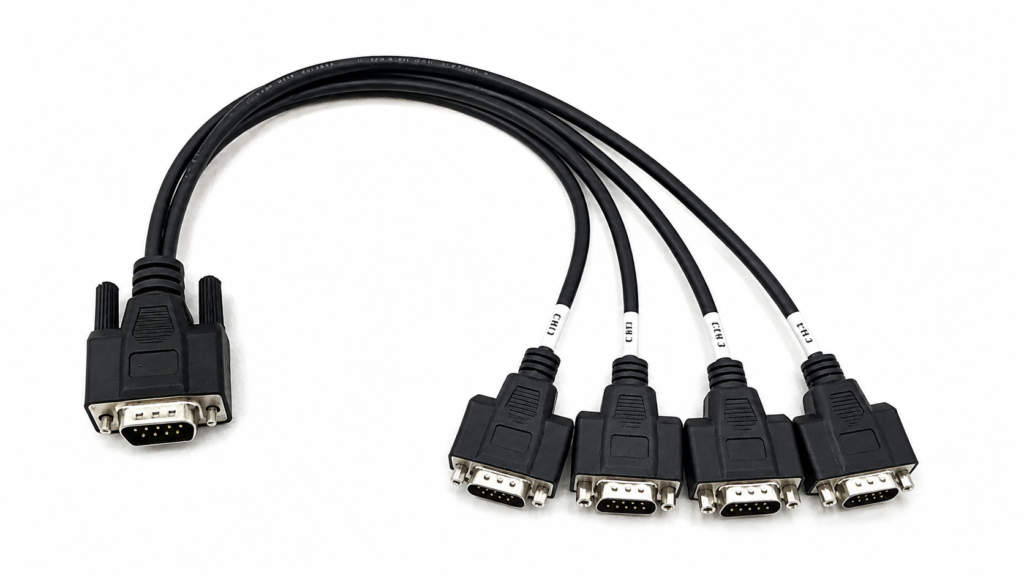
A DB25-to-XLR breakout, for example, needs more than the connector names. The quotation also depends on the number of branches, XLR gender, channel order, branch length, individual cable diameter, identification sleeves, fan-out protection, and packaging method. A DB25-to-flying-lead assembly requires conductor colors, strip lengths, ferrules, terminals, and wire markers.
NI publishes a dedicated mapping document for its SH25F-25M cable that identifies twisted-pair relationships and conductor color codes. This demonstrates why a product designation and connector description should be supported by an actual wire map and dimensional definition.
When several variants share a similar appearance, each version should have a controlled part number or option code. Differences in gender, exit direction, branch layout, pinout, or cable length may require separate work instructions, test programs, labels, and packaging.
Wiring Format
State whether the assembly is straight-through, crossover, breakout, loopback, or based on a proprietary wiring plan. These terms are helpful, but they should not replace a complete pin-to-pin table. “Straight-through” does not explain shield termination, shell bonding, unused contacts, internal jumpers, connector-view orientation, or whether all 25 positions are populated.
A crossover cable intentionally changes selected signal paths. NI’s serial conversion documentation, for example, shows that a DB25 contact number may map to a different DB9 or RJ50 contact according to the communication function. Transmit, receive, grounding, and control signals cannot be assigned reliably by matching connector position alone.
Breakout assemblies require another level of detail because one DB25 connector may distribute signals among several smaller connectors or individual conductors. The drawing should identify the destination connector, destination pin, branch number, signal name, shield treatment, and branch length.
When an old cable is the only reference, continuity mapping can support reverse review. The resulting map should still be documented, checked against the equipment, and approved before material purchasing or production begins.
Installation Conditions
Describe how the cable will be routed, secured, handled, and serviced throughout its working life. A fixed cable inside a clean cabinet has different requirements from a cable that is coiled daily, connected to portable test equipment, exposed to vibration, or installed beside motors and high-current wiring.
Useful details include available bend space, expected movement, connector mating frequency, vibration, pulling risk, temperature, humidity, dust, oil exposure, nearby interference sources, and whether technicians need to open or replace the backshell in the field. These conditions influence cable flexibility, jacket selection, shielding, retention hardware, strain relief, and inspection requirements.
Oracle’s EIA-232 guidance recommends shielded, low-capacitance cable for the equipment covered by its documentation and advises routing away from transformers, generators, motors, and other electromagnetic-noise sources where possible. It also explains that total capacitance and data rate affect the practical cable run. These are application-specific considerations, but they show how the operating environment belongs in the RFQ.
A useful application description does not need to become a long technical report. A few accurate sentences, supported by equipment photographs and a simple installation sketch, can eliminate many of the assumptions that would otherwise be hidden inside the quotation.

Which Connector Details Must Be Confirmed?
Each DB25 connector should be defined by gender, exact model or approved equivalent, contact type, termination method, backshell, mounting hardware, cable-exit direction, shielding, and strain relief. These details influence component availability, mechanical fit, assembly labor, tooling, inspection, and production repeatability. A correct pinout cannot compensate for a connector that does not mate, lock, or fit the available installation space.
| Connector detail | Options to confirm | Quotation impact | Useful evidence |
| Gender | Male plug or female receptacle | Changes housing and contact selection | Port photo and drawing |
| Connector source | Specified brand, approved equivalent, general option | Affects component price, MOQ, and availability | Part number or approved vendor list |
| Termination | Solder cup, crimp, IDC, another controlled method | Changes contact type, tooling, and labor | Connector datasheet |
| Backshell | Plastic, metal, shielded, low profile, molded | Affects dimensions, EMI control, and protection | Backshell model or reference sample |
| Cable exit | Straight, left, right, upper, lower | Influences installation clearance | Mechanical drawing |
| Retention | Jackscrew, jackpost, slide lock, panel hardware | Controls mating compatibility | Thread and hardware specification |
| Mounting | Free-hanging, front panel, rear panel | Changes hardware and assembly sequence | Equipment drawing |
| Strain relief | Cable clamp, boot, heat shrink, overmold | Influences durability, tooling, and repairability | Approved structural drawing |
Gender and Mating Interface
Identify each end as a male plug or female receptacle and confirm the mating connector installed on the equipment. Informal descriptions such as “the male side of the machine” can create confusion, particularly when a photograph is taken from an angle or the equipment uses a recessed connector.
TE Connectivity lists separate 25-position plug and receptacle products. Its product data also distinguishes cable-to-cable, cable-mounted, panel-mounted, and board-mounted arrangements. Two products may both have 25 positions while using different contact genders, shell constructions, mounting methods, and termination systems.
A practical RFQ description could state that End A is a DB25 male cable plug mating with a female controller port, while End B is a DB25 female cable receptacle mating with a male I/O module. Supporting photographs should show the connector face and the surrounding equipment.
This simple cross-check can prevent a sample from being built with the correct wiring but the wrong mechanical interface. Connector gender errors may require new connectors, backshell rework, revised overmolding, repeated testing, and another round of sample approval.
Part Number and Termination
Provide the exact connector manufacturer and part number whenever the project controls the source, contact plating, temperature range, retention method, termination system, or compliance documentation. When an equivalent is acceptable, state which characteristics must remain unchanged and which substitutions require written approval.
DB25 contacts may be terminated by soldering, crimping, insulation displacement, or another connector-specific method. Each process requires compatible contacts, conductor preparation, tooling, inspection, and repair procedures. A connector designed for a flat cable or board connection should not be selected for a round multicore cable simply because the outer shell appears familiar.
TE product data illustrates these distinctions. One 25-position receptacle is described as a cable-to-cable, panel-mount connector, while another 25-position product is a free-hanging cable mount. Other models specify crimp termination, separate contacts, or a 90-degree cable exit.
Availability should be reviewed before sample timing and production scheduling are confirmed. A controlled part may have a high minimum purchase quantity, long sourcing time, regional availability issue, or obsolete status. Any alternative should be documented and approved before sampling.
Backshell and Cable Exit
The backshell protects the termination area, supports cable retention, provides room for shielding connections, and determines the direction in which the cable leaves the connector. It is therefore both an electrical and mechanical part of the assembly rather than a decorative cover.
A plastic serviceable hood may be suitable for a stationary indoor application where technicians need access to the terminations. A metal backshell may be selected where stronger mechanical protection or shield continuity is required. A low-profile or angled design may be necessary when the port is close to a cabinet wall, neighboring connector, rack rail, or access cover.
The cable-exit direction must be defined from a stated viewing position. “Left exit” is ambiguous unless the drawing explains whether the connector is viewed from the mating face, cable side, or front of the equipment. Marking pin 1 and showing the equipment orientation usually removes this uncertainty.
Cable outer diameter must also be checked against the backshell entry and clamp range. A heavily shielded multi-pair cable may meet the electrical requirement but be too large for the preferred low-profile shell. That conflict should be resolved during engineering review.
Locking and Strain Relief
Confirm how the connector is retained after mating. Common arrangements include jackscrews, jackposts, threaded inserts, slide locks, panel hardware, and customer-specific brackets. The screw thread, hardware length, mounting position, and available tool clearance must match the equipment.
TE’s D-sub product data shows that similar 25-position connectors may use different mounting arrangements and mating-retention features. One product may be free-hanging, another panel-mounted, and another designed with threaded inserts or cable-exit geometry that changes the final assembly.
Strain relief should be selected according to handling and installation. Options may include an internal cable clamp, flexible boot, heat-shrink reinforcement, assembled hood, or custom overmold. Overmolding can support a controlled cable exit, connector protection, strain distribution, tamper resistance, and repeatable appearance, but it may require tooling, sample validation, material confirmation, and a suitable production quantity.
Cablivo’s verified project capabilities include connector confirmation, overmold-structure review, tooling discussion, prototype development, sample revision, cable assembly, and production preparation.

How Should the Pinout Be Defined?
The pinout should be supplied as an approved pin-to-pin table or controlled wiring drawing. It must identify each used contact, signal name, destination, conductor group, shield connection, unused position, jumper, and connector-view orientation. Because DB25 connectors serve many different systems, there is no universal wiring arrangement that can be applied safely to every DB25 cable assembly.
| Pinout field | Information to record | Example format | Selection value |
| End A contact | Physical connector position | A2 | Establishes the source contact |
| Signal name | Electrical function | TXD, Channel 1+, Input 4 | Helps verify circuit logic |
| Conductor ID | Color, number, or print code | W02, White/Blue | Supports production and inspection |
| Pair or group | Twisted pair, channel, power group | Pair 1, Channel 1 | Defines cable construction |
| End B destination | Connector and contact | B3, XLR1 Pin 2 | Controls termination |
| Shield treatment | Shell, pin, drain, or open | Drain to shell at End A | Defines grounding |
| Unused contact | NC, reserved, or not populated | Pin 18: NC | Removes hidden assumptions |
| Drawing orientation | Mating face or wire side | End A mating-face view | Prevents mirrored wiring |
Pin-to-Pin Mapping
Create one row for every position, even when several contacts are not used. A complete table makes it easier to review the design, build the sample, program the electrical tester, inspect production, and manage future revisions.
The table should identify the End A contact, signal name, conductor ID, pair or channel group, End B destination, and any special termination instruction. Unused contacts should be marked clearly as not connected, reserved, not populated, or another controlled status. A blank cell can be interpreted as missing information, an open circuit, or an intentional omission.
NI’s SH25F-25M documentation provides a separate wire-mapping list that identifies which conductors form twisted pairs and records their color codes. This level of mapping is useful because the connector names alone do not explain the internal structure.
For a breakout cable, specify both the destination connector and its destination pin. “DB25 pin 2 to XLR channel 1” remains incomplete unless the required XLR contact is identified. The same principle applies to terminal blocks, circular connectors, headers, and prepared leads.
Signal Names and Pairing
Add the electrical function beside every active contact. Signal names help the engineering team identify logical conflicts that may not be obvious from contact numbers alone.
An EIA-232 cable may include transmitted data, received data, request to send, clear to send, data terminal ready, signal ground, and other control signals. A balanced analog audio assembly may group hot, cold, and ground conductors for several channels. An industrial control cable may carry inputs, outputs, common lines, interlocks, and reserved circuits.
Oracle publishes a DB25 EIA-232 pin assignment for specific serial equipment, while TASCAM publishes an AES59-2012-compliant DB25 arrangement for multiple balanced audio channels. These are both legitimate uses of the connector family, but the signal systems are different.
When the cable uses twisted pairs, identify which two conductors belong together. Do not expect the production team to infer pair grouping from neighboring pin numbers. Pair assignment influences cable selection, termination order, shield grouping, and test documentation.
Grounds, Shields, and Jumpers
Define how signal ground, chassis ground, connector shells, overall shields, pair shields, and drain wires should be connected. Grounding should come from the equipment design or an approved project specification, not from a general assumption about DB25 cables.
Possible arrangements include bonding an overall shield to both connector shells, connecting it at one end only, terminating individual shields to designated contacts, keeping shells isolated, or separating chassis ground from signal ground. Each choice affects the wiring instruction, backshell design, test plan, and compatibility with the surrounding system.
Oracle’s EIA-232 guidance recommends grounding the cable shield at both ends through the DB25 connector shells for the equipment covered by that document. That arrangement should not be copied automatically into unrelated audio, control, or proprietary applications without approval.
Internal jumpers should also be shown in the schematic or pin table. A bridge between contacts adds conductor preparation, soldering or crimping work, insulation, inspection points, and test conditions. If resistors, diodes, ferrites, or other parts are installed inside the backshell, provide a schematic and BOM.
Pin-View Control
Every connector drawing should state whether it is shown from the mating face, rear wire side, solder side, or equipment side. Mark pin 1 and enough reference positions to make the orientation unmistakable.
A mirrored pinout is easy to create when a male connector and female connector are shown from opposite directions or when a customer combines photographs, hand drawings, and manual pages prepared from different viewpoints. The finished assembly may appear neat and mechanically correct while every contact is reversed.
Useful drawing labels include “End A, DB25 male, mating-face view” and “End B, DB25 female, wire-side view.” The cable-exit direction should also be marked relative to the equipment front or another fixed reference.
The approved pinout becomes more than an engineering drawing. It is the basis for sample assembly, tester programming, work instructions, first-article review, production inspection, and change control. Cablivo’s documented capabilities include wire-sequence confirmation, pinout review, continuity testing, and production preparation.

What Cable Specifications Are Needed?
A complete DB25 cable specification defines conductor count, wire size, stranding, pair arrangement, insulation, shielding, drain wires, jacket material, outer diameter, finished length, tolerance, flexibility, color, and identification. The selected structure must fit the connector and backshell while satisfying the electrical, mechanical, environmental, and production requirements of the actual application.
| Cable characteristic | Common choices | Selection value | Points to verify |
| Conductor arrangement | Individual cores, twisted pairs, mixed groups | Matches signal and channel layout | Active, spare, and ground conductors |
| Wire size | Project-defined AWG or cross-section | Influences resistance, flexibility, and diameter | Contact and backshell compatibility |
| Shielding | None, foil, braid, foil plus braid, pair shields | Supports interference control | Grounding and drain-wire method |
| Jacket | PVC, TPE, TPU, PUR, PE, specified compound | Matches handling and environment | Exact grade and documentation |
| Finished length | Face-to-face, shell-to-shell, trunk plus branches | Prevents dimensional disputes | Datum and tolerance |
| Outer diameter | Target and maximum value | Controls routing and backshell fit | Clamp range and bend radius |
| Flex requirement | Fixed, occasional movement, repeated movement | Influences stranding and jacket | Bend location and test conditions |
| Identification | Color, printed code, labels, numbered cores | Supports installation and servicing | Artwork, location, and durability |
Conductors and Wire Size
State the number of conductors and how they are arranged. A 25-position connector does not automatically require 25 identical insulated wires. The assembly may use only selected contacts, include spare conductors, combine several twisted pairs, carry separate grounds, or use different conductor sizes for signal and low-voltage power circuits.
Wire size affects resistance, voltage drop, flexibility, cable diameter, contact compatibility, mechanical strength, and termination quality. The appropriate AWG or cross-sectional area should be selected from the current, voltage, signal type, cable length, allowable voltage drop, connector contact range, movement, and available backshell space.
Selecting a larger conductor simply because it appears more robust can create another problem. The completed bundle may not fit the solder cups, crimp contacts, cable clamp, or backshell opening. A very small conductor may fit easily but provide inadequate retention or electrical performance.
When the required AWG is not already controlled by a drawing, provide the operating voltage, maximum current, signal type, length, and installation conditions needed for review. Cablivo’s project-information checklist includes connector model, cable length, wire size, quantity, application, packaging, and testing requirements.
Shielding Structure
Specify whether the cable requires no shield, an overall foil shield, an overall braided shield, foil plus braid, individually shielded pairs, or a combined structure. The appropriate option depends on the signals, surrounding interference, cable movement, connector space, and grounding method.
Foil shielding can provide broad coverage while keeping the structure relatively compact. Braided shielding can support flexibility, mechanical protection, and low-resistance shield continuity. Foil plus braid may be selected when both coverage and robustness are important. Individually shielded pairs may help separate channels or sensitive circuits.
The shielding choice affects cable diameter, flexibility, material cost, stripping, backshell space, termination time, and inspection. It should therefore be connected to a defined electrical requirement rather than added as a general quality phrase.
Oracle recommends shielded, low-capacitance cable for the EIA-232 equipment covered by its documentation. This illustrates how shielding should follow the interface and installation requirement.
Cablivo’s verified production base includes braiding, aluminum-foil wrapping, shield processing, cable extrusion, termination, and assembly equipment. The approved drawing should still define exactly how the shield and drain wire are terminated.
Length and Dimensions
Define the finished cable length and the exact points from which it is measured. “Two meters long” may refer to connector face to connector face, cable jacket between backshells, total tip-to-tip length, or the main trunk before a breakout. These methods can produce noticeably different finished assemblies.
A controlled drawing should identify the overall length, measurement datum, trunk length, branch point, branch lengths, staggered dimensions, strip lengths, exposed conductors, connector dimensions, backshell dimensions, and permitted tolerance.
For a rack-mounted breakout, branch length and channel order may be as important as the main cable length. For an electrical cabinet, the assembly may need enough length for ducts, corners, and a service loop without creating excessive slack.
Length can also affect electrical performance in some applications. Oracle’s EIA-232 reference explains that the total capacitance of the cable and connectors affects signal integrity and that the acceptable run changes with data rate and cable capacitance. These values apply to the referenced equipment, but they demonstrate that cable length should be reviewed against the real interface rather than chosen only from physical distance.
Jacket and Flexibility
Select the jacket material from the environment, movement, handling pattern, and compliance requirement. PVC is widely used in general cable construction, while TPE, TPU, PUR, PE, and other specified compounds may be selected where flexibility, abrasion resistance, temperature behavior, oil exposure, outdoor use, or a particular surface characteristic matters.
Describe whether the cable is fixed, moved occasionally, repeatedly flexed, coiled, dragged, exposed to oil, installed near heat, or routed through a restricted space. Include the desired color, outer diameter, surface finish, printed identification, and minimum bend considerations.
A highly flexible cable may require fine-stranded conductors, a suitable jacket, carefully selected shielding, and a longer strain-relief transition. A rugged cable may provide more protection but increase stiffness and diameter. The correct choice balances electrical performance, installation, handling, connector space, manufacturing process, and expected service.
Cablivo’s verified manufacturing system includes conductor preparation, insulation extrusion, jacket extrusion, shielding, cutting, stripping, termination, and finished assembly. Material and compliance requirements should still be confirmed according to the selected product, actual compound, and target market.

Which Performance and Test Requirements Apply?
Testing should be defined from the cable’s electrical function, operating environment, and failure risk. The RFQ should identify the signals, voltage, current, communication parameters, inspection methods, acceptance limits, sample size, and reporting needs. Continuity testing confirms basic electrical paths, but it does not automatically verify signal performance, insulation, mechanical strength, repeated movement, labeling, or equipment compatibility.
| Test or review | What it checks | Suitable situation | Information required |
| Continuity | Open circuits and completed paths | Most wired assemblies | Maximum resistance if controlled |
| Pinout or wire sequence | Correct contact mapping | Custom and proprietary pinouts | Approved mapping revision |
| Short-circuit test | Unintended contact between circuits | Densely terminated multicore cables | Circuits included in the check |
| Connector-fit check | Mating and locking compatibility | New connector or replacement projects | Mating part or equipment sample |
| Insulation resistance | Electrical isolation | Higher-risk signal or power circuits | Test voltage and minimum result |
| Hi-Pot | Dielectric withstand | When required by specification | Voltage, duration, leakage limit |
| Pull-force test | Terminal or joint retention | Crimped, soldered, or molded joints | Force, direction, duration |
| Flex or swing test | Repeated-bend durability | Moving or frequently handled cables | Bend angle, load, cycle count |
| Functional test | Operation in the intended system | Proprietary or signal-sensitive assemblies | Fixture and pass criteria |
| Dimensional inspection | Length and structural conformity | Controlled cable assemblies | Dimensions and tolerances |
| Label and packaging check | Identification and shipment accuracy | Multi-SKU and branded programs | Approved artwork and pack plan |
Electrical Function
List the signal type, operating voltage, maximum current, protocol, grounding arrangement, and any safety-related circuit function. The assembly may carry serial communication, balanced audio, digital inputs and outputs, contact closures, sensor signals, control power, or a combination of several functions.
This information influences conductor size, insulation, pair arrangement, shielding, contact selection, test voltage, and inspection method. A generic rating taken from another connector should not be applied automatically to the full cable assembly.
TE’s 25-position D-sub product data shows that connectors with the same position count can differ in contact gender, termination method, mounting arrangement, operating temperature, contact system, and other characteristics. Some TE models list crimp contacts and maximum contact ratings, while other 25-position products use different structures. The exact selected connector and contact must therefore be reviewed.
For signal-sensitive systems, include data rate, capacitance, impedance, resistance, crosstalk, or frequency limits when the equipment specification controls them. These parameters should not be added without a real application need, but they should not be omitted when system performance depends on them.
Environment and Reliability
Describe the conditions the cable will experience during operation, handling, transportation, storage, and maintenance. Important factors include temperature, humidity, vibration, repeated bending, connector mating frequency, accidental pulling, abrasion, oil, coolant, dust, moisture, and nearby electromagnetic-noise sources.
A stationary assembly inside a clean rack may need only basic mechanical protection. A moving industrial cable may require flexible conductors, a suitable jacket, stronger strain relief, and a controlled bending test. A service cable used by technicians may require repeated connector mating, clear identification, and a more repairable backshell.
Oracle’s EIA-232 documentation recommends routing the referenced serial cables away from transformers, generators, motors, and fluorescent lighting where possible. It also connects shielding, capacitance, data rate, and cable length to communication reliability. These details are specific to that interface, but they demonstrate how installation conditions can influence cable construction and testing.
Reliability requirements should be measurable. Phrases such as “industrial grade,” “very durable,” or “strong strain relief” do not define acceptance. Replace them with an approved material, dimension, pulling force, bending condition, environmental range, mating requirement, or verified reference sample.
Test Scope and Acceptance
Specify which tests apply to engineering samples, first articles, routine production, periodic validation, or all finished units. The test plan should state the method, fixture, applied value, duration, sample size, and pass-or-fail limit.
A requirement such as “pull test needed” remains incomplete until the force, direction, holding time, sample quantity, and failure definition are confirmed. A Hi-Pot requirement needs the voltage, duration, leakage limit, and circuits under test. A flex test needs the bend angle, bend radius, load, speed, movement location, and number of cycles.
For custom pinouts, continuity and wire-sequence testing are fundamental because they identify open circuits, shorts, and incorrect mappings. A functional test with the actual equipment or a validated fixture may be needed when an ordinary cable tester cannot reproduce the system behavior.
Cablivo’s verified quality capabilities include continuity, wire sequence, pinout, connector fit, pull force, insulation, bending, appearance, labeling, packaging, and other project-defined checks. The test scope depends on the product and project rather than every available test being applied automatically.
Reports and Documentation
State which records must accompany the sample, first article, production lot, or shipment. Common documents include the approved drawing, BOM, pinout record, first-article inspection report, dimensional report, continuity result, certificate of conformity, material declaration, lot record, packaging approval, or a customer-specific inspection form.
Documentation can influence the quotation and schedule. A normal production test may be part of the manufacturing process, while a full dimensional report, customer-formatted data sheet, lot-level traceability, or third-party test may require additional inspection and administrative work.
Compliance statements should be connected to the actual connector, cable material, production method, target market, and available supplier documents. A broad phrase such as “all certifications included” does not reflect the way custom cable projects are evaluated.
Cablivo’s factual content rules require certification and testing needs to be reviewed according to product type, material, market, and project specification. They also prohibit invented test values, report numbers, pass rates, or universal certification claims.

How Do You Submit a Quote-Ready RFQ?
A quote-ready DB25 RFQ brings the technical and commercial requirements into one controlled package. It should include the application, equipment, connector details, pinout, cable structure, dimensions, testing criteria, sample quantity, production volume, packaging, delivery destination, and approval method. The purpose is not to create unnecessary paperwork, but to remove assumptions before pricing, sampling, and material purchasing begin.
| RFQ package item | Minimum useful content | Strong supporting evidence | Quotation value |
| Project summary | Equipment and cable function | Installation photo or system diagram | Identifies the correct assembly category |
| Connector data | Gender, model, mating part | Datasheet and port photo | Supports sourcing and fit review |
| Pinout | Pin-to-pin mapping | Signal names and connector-view drawing | Controls wiring and testing |
| Cable specification | AWG, cores, shield, jacket, length | Cable datasheet or approved sample | Supports material and process pricing |
| Mechanical drawing | Length, branches, cable exit | Dimensioned drawing with tolerances | Prevents dimensional assumptions |
| Test plan | Required inspections | Values, methods, sample size, reports | Defines quality cost and acceptance |
| Quantity | Samples, first order, forecast | SKU list and ordering plan | Supports realistic pricing |
| Packaging | Protection, labels, carton method | Artwork and pack-out drawing | Prevents hidden finishing costs |
| Delivery | Destination and requested timing | Shipping instruction | Supports schedule and logistics review |
| Approval | Sample-review and release method | Golden sample or approved drawing | Controls production release |
Drawings and Reference Files
Send the most controlled information available. A useful package may include an assembly drawing, pin-to-pin table, electrical schematic, BOM, connector datasheets, equipment-manual pages, port photographs, original-cable photographs, dimensional sketches, label artwork, packaging specification, and testing requirements.
Identify the controlling document and revision. Conflicts often occur when a drawing shows one connector model, the BOM lists another, and an email contains a different pinout. The manufacturer should identify these discrepancies and record quotation assumptions before pricing is finalized.
File names should be clear enough for engineering, sourcing, quality, production, and purchasing teams to identify the correct revision. A project number, product number, document type, revision, and date are more reliable than several files named “final” or “latest.”
Cablivo’s documented engineering scope includes requirement review, drawing review, sample review, BOM review, connector confirmation, wire-sequence confirmation, pinout review, material selection, DFM feedback, prototype development, sample revision, and production preparation.
Quantity and Commercial Details
Request quotations for the quantities that reflect the real project path. Many projects move from engineering samples to a pilot order, an initial production order, and later recurring purchases. Listing these stages separately helps the manufacturer distinguish one-time engineering or setup work from repeat production cost.
Useful commercial information includes the number of variants, expected ordering frequency, initial volume, annual forecast when available, customer-supplied materials, approved component sources, tooling ownership, delivery destination, packaging level, and requested shipping terms.
A quotation for five engineering samples cannot be compared directly with a quotation for several thousand repeat units. Sample quantities may require hand preparation, short material purchases, engineering time, and individual testing, while production pricing may depend on bulk component sourcing, fixtures, tooling, work instructions, and packaging efficiency.
Cablivo’s standard MOQ guidance starts from 500 pieces for many custom cable projects, while the final MOQ depends on connector type, cable structure, materials, overmolding, tooling, packaging, and order quantity.
Lead time should be reviewed after connector availability, material preparation, tooling, testing, quantity, packaging, and sample approval are understood rather than promised from the phrase “DB25 cable” alone.
Packaging and Delivery
Define how the cable must be protected, identified, packed, and delivered. DB25 assemblies may contain exposed pins, threaded hardware, metal shells, long branches, small labels, or carefully controlled bend transitions. Poor packaging can damage a product that has already passed electrical and dimensional inspection.
Confirm whether the cable is individually bagged or bulk packed, whether the connector needs a cap or protective tray, the required coiling diameter, cable-tie method, branch organization, inner-box quantity, carton quantity, barcode, customer part number, revision, lot code, origin marking, instruction sheet, and carton mark.
Similar-looking DB25 variants are particularly vulnerable to mixing. A clear label and packaging plan helps distinguish different genders, pinouts, lengths, branch layouts, and equipment applications before the products reach the installation site.
Cablivo’s verified project support includes packaging, labeling, inspection, warehouse handling, and shipment coordination. Packaging files and label information should be reviewed before production so they are included in the quotation and sample approval rather than treated as a final-stage addition.
Samples and Production Approval
When no complete drawing exists, begin with the verified information rather than waiting for a perfect specification. Useful starting materials include connector photographs, equipment photographs, an existing cable, approximate length, measured pin mapping, application details, target quantity, and any known installation problem.
An original sample can support connector identification, continuity mapping, dimensional review, material comparison, and packaging discussion. If destructive inspection is needed, the customer should authorize it. The findings should then be converted into a controlled drawing, BOM, pinout, or approved sample record.
Sample approval should identify who performs the review, which drawing revision applies, what electrical and dimensional tests are required, how equipment-level compatibility is checked, how feedback is recorded, and what conditions release the project to production.
The approved connector models, cable construction, pinout, dimensions, labels, testing criteria, and packaging become the production baseline. Later changes should be reviewed for their effect on material, price, tooling, testing, sample status, and delivery.
Cablivo’s fact base states that projects without complete drawings can begin with sample photographs, connector photographs, cable length, application information, and target quantity. The available information can then be reviewed to identify what remains to be confirmed before sampling.
For a custom DB25 cable assembly quotation, send the drawing, pinout table, connector models, cable specification, required length, sample quantity, expected production volume, testing criteria, packaging files, and delivery information together. When a detail is not yet known, mark it as open rather than allowing it to become an unrecorded assumption.
Cablivo is the overseas-facing website brand of Shenzhen Tianxiaowei Electronics Co., Ltd., a Shenzhen-based custom cable, wire harness, and cable assembly manufacturer with 18 years of industry experience, more than 20,000 square meters of factory space, a team of more than 1,500 people, and three manufacturing bases. Its project support covers drawing and BOM review, connector and pinout confirmation, sample development, production, testing, packaging, labeling, and shipment coordination.
Submit your DB25 project information to Cablivo for engineering review and quotation. A complete RFQ helps the team evaluate connector sourcing, cable structure, manufacturing processes, testing, packaging, MOQ, and production preparation on the same technical basis, reducing repeated clarification and helping the approved sample move into stable production with fewer avoidable changes.



