 Skip to content


A control panel wire harness can be electrically correct on paper and still create serious trouble during installation. A branch may leave the main bundle in the wrong direction, a connector may be keyed incorrectly, a wire marker may disappear inside the wire duct, or a cable may fall just short of the terminal block. These details influence materials, labor, testing, installation time, rework risk and the final quotation.
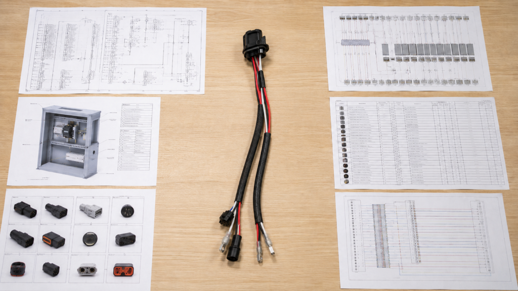
To quote a control panel wire harness accurately, the manufacturer needs the latest drawings, BOM, wire specifications, connector and terminal part numbers, pinout, wire sequence, trunk and branch dimensions, routing information, labels, testing requirements, quantities and packaging instructions. When formal drawings are incomplete, clear sample photos, connector photos and a structured point-to-point wire list can support the initial review.
The problem is easy to see when two suppliers quote the same “twenty-wire control panel harness.” One may calculate only the conductors and terminals. Another may include ferrules, printed wire markers, protective sleeve, branch ties, programmed continuity testing, individual packing and connector protection. The first number may look lower, but the two quotations do not describe the same finished assembly. An accurate quotation begins by making the entire product visible before anyone calculates the price.
What Project Files Should You Send?
Send the latest harness drawing, electrical schematic, point-to-point connection list, control panel layout, BOM, connector information, label files and any available sample photos. These files explain what must connect, where the harness must fit and which components must be purchased. When formal documentation is incomplete, photos can support a preliminary review, but critical dimensions and electrical details still need confirmation.
Which Drawings Matter Most?
A control panel wire harness is both an electrical assembly and a physical installation component, so one file rarely describes the whole project. The harness drawing shows the main trunk, branch points, branch lengths, connector positions, sleeves, labels and dimensional tolerances. The electrical schematic explains the function of each circuit, while the panel layout shows where PLCs, relays, terminal blocks, drives and power supplies are positioned inside the cabinet.
A point-to-point connection list is especially useful when a project contains many individual conductors. It turns a complex schematic into a structured manufacturing reference by identifying the source device, source terminal, destination device, destination terminal, wire number, wire size, color and signal function. This same list can later become the foundation for continuity testing, which reduces the chance that manufacturing and inspection teams interpret the wiring differently.
What Should the BOM Include?
The BOM should list every component that becomes part of the finished harness, not only the wire and connector housings. A reliable BOM normally includes conductors, connector housings, contacts, terminals, ferrules, lugs, seals, secondary locks, heat-shrink tubing, sleeves, cable ties, labels, connector caps and packaging materials. Missing secondary components are a common reason an early quotation changes after engineering review.
Each line should show a clear description, manufacturer, part number, quantity per harness and substitution rule. A description such as “four-pin connector” is not enough because visually similar connector families may use different contacts, keying systems, wire ranges or crimp tools. When the original component is mandatory, it should be marked as no substitution. When alternatives are acceptable, the approval process should be stated so that cost and sourcing decisions remain controlled.
Can Photos or Samples Be Used?
Photos and physical samples are useful when an existing harness is being reproduced, a project is moving from another supplier or formal drawings have not yet been completed. A good photo set includes one full view of the harness, clear close-ups of every connector face, branch junctions, terminal details, sleeve endings, label positions, connector exit directions and the original packaging. A ruler or known reference dimension helps reduce scale errors.
Photos alone usually cannot confirm internal pinout, exact terminal part numbers, conductor construction or hidden accessories. A physical sample provides more information, but it may have been repaired, stretched or modified during field use. The safer approach is to treat the sample as a reference and then create or approve a controlled drawing, BOM and connection list before repeat manufacturing begins.
How Should Revisions Be Controlled?
Every document in the RFQ package should show a revision number or issue date. The quotation cover sheet should identify which drawing, BOM, schematic, point-to-point list and label file are current. Without this control, one supplier may quote a newer drawing while another uses an older BOM, making the prices impossible to compare on equal terms.
Conflicting revisions can also create production mistakes. A revised drawing may show twelve branches while the previous BOM contains only ten connector sets. A new schematic may change one terminal destination without updating the wire list. A simple document register listing the file name, revision, date and approval status prevents old information from quietly entering sampling or mass production.
| Project document | Minimum information | Quotation value | Risk when missing |
| Harness drawing | Trunk, branches, lengths, connectors, sleeves and labels | Defines material use and assembly work | Supplier may price only loose wires |
| Electrical schematic | Circuit function, voltage, signal and grounding | Supports electrical and material review | Circuit assumptions remain unclear |
| Point-to-point list | Source, destination, pin, wire ID and function | Supports wiring and test preparation | Pinout or wire-sequence errors |
| Panel layout | Device locations, wire ducts and routing | Helps evaluate physical fit | Harness may not suit the cabinet |
| BOM | Part numbers, quantities and substitution rules | Supports material and sourcing costs | Terminals, seals or accessories may be missed |
| Label file | Label text, format, size and position | Defines printing and application work | Identification added after quotation |
| Revision register | Current file versions and approval status | Keeps all suppliers on one scope | Quotations may use different specifications |
A complete file package does not need to look complicated. It simply needs to make the electrical connections, physical installation, materials and commercial scope clear enough for engineering, purchasing and production teams to work from the same information.

Which Electrical Details Define the Harness?
Define every conductor’s gauge, material, insulation, color, voltage, current, source, destination, pin position and signal function. The RFQ should also state polarity, shielding and grounding requirements where applicable. These details determine conductor selection, terminal compatibility, crimping methods, electrical testing and whether the finished harness can operate correctly inside the control panel.
What Wire Specifications Are Needed?
Each wire or cable type should be identified by conductor size in AWG or square millimeters, conductor material, insulation type, color and applicable project specification. When flexibility, temperature exposure, oil contact, abrasion or flame performance matters, the project should define the required condition or approved material rather than using a broad phrase such as “industrial wire.”
A single control panel harness may contain several wire categories, including individual control wires, higher-current power conductors, protective earth wires, multicore cables, shielded signal cables and communication cables. Each wire number should map to the correct specification. Applying one general wire note to the entire harness can create errors when different circuits require different insulation, conductor sizes or termination methods.
Wire colors support installation and service work, but color should not replace wire numbering. Large cabinets often reuse the same color across many circuits. A unique wire ID tied to the schematic and connection table creates a more reliable method for production, testing and future maintenance.
How Should the Pinout Be Defined?
A complete pinout identifies both ends of every conductor. It should state the source device, source terminal or connector cavity, destination device, destination terminal or cavity, wire number, conductor specification and signal function. For connectorized branches, the drawing should also define whether the connector view is shown from the mating side or the wire side.
This viewing direction matters because the apparent pin sequence can reverse when a connector is viewed from the opposite face. A drawing that shows only circles numbered one through eight without a defined viewing direction can lead to a harness that appears correct but connects the circuits in reverse order.
Terminal-block connections also need clear references. The connection list may identify the terminal strip, terminal number and connection side. PLC connections may require rack, slot, channel and terminal information. Once these details are organized, the same data can support programmed continuity and open-short testing.
Which Connectors and Terminals Must Be Confirmed?
Every connector housing, contact, terminal, ferrule, lug, seal, secondary lock, backshell and mating component should be identified by an exact part number whenever possible. Connector confirmation should cover the manufacturer, series, pin count, male or female configuration, keying, coding, orientation, mating part, compatible wire range and termination method.
Terminal compatibility is equally important. A ring terminal must match the stud size. A ferrule must suit both the conductor and the terminal-block entry. A connector contact must fit the housing cavity and the selected wire size. A component that looks similar is not necessarily interchangeable.
When an original connector is difficult to source, the manufacturer may propose an alternative for approval. The comparison should cover fit, keying, current capability, wire range, locking method, availability and any tooling changes. The alternative should never be introduced silently because a small component change can affect installation, testing and future repeat orders.
What Shielding and Grounding Details Matter?
A requirement such as “use shielded cable” does not fully define the assembly. The RFQ should state the cable construction, shield type, drain wire arrangement, grounding location and termination method. Common structures include foil shielding, braided shielding, combined foil and braid, and a separate drain wire used to connect the shield to ground.
The drawing should also explain whether the shield is bonded at one end, both ends or through a dedicated terminal. This decision depends on the control system, signal type and equipment grounding design. The harness manufacturer should follow the approved electrical design instead of selecting a grounding strategy without sufficient information.
Power and low-level signal conductors may also require separate routing or bundle groups. Analog sensors, encoders, communication lines and high-current circuits can have different installation considerations. Defining these requirements before quotation allows the manufacturer to evaluate cable structure, sleeve grouping and testing work more accurately.
| Electrical item | Typical specification | What it affects | Confirmation question |
| Wire gauge | AWG or mm² by wire number | Wire cost, terminals and stripping setup | Does the terminal support the selected wire range? |
| Voltage | Circuit or system voltage | Insulation and test planning | Is the approved wire specification identified? |
| Current | Normal or maximum circuit current | Conductor and terminal review | Has the conductor size been approved for the circuit? |
| Pinout | Source and destination cavities | Assembly and continuity testing | Is the connector viewing direction clear? |
| Polarity | Positive, negative and directional circuits | Functional accuracy | Is polarity identified at both ends? |
| Shielding | Foil, braid, drain wire and termination | Cable structure and labor | Where and how is the shield grounded? |
| Grounding | PE, functional earth or signal ground | Wire color and termination | Are the ground functions clearly separated? |
| Wire marking | Unique wire ID and format | Installation and maintenance | Can each conductor be traced to the schematic? |
Electrical details give the quotation its technical foundation. Without them, a supplier may estimate an assembly that looks similar but uses different wire, terminals, pin assignments or shielding methods from the product the project actually requires.

What Mechanical Details Affect Pricing?
Mechanical details determine how much wire, sleeve and protection material is used and how much work is required to cut, branch, label, fixture, inspect and package the harness. Provide trunk length, branch dimensions, breakout positions, measurement references, tolerances, routing restrictions, connector directions and protective materials. A schematic may define correct connections, but it cannot confirm that the harness will fit the cabinet.
How Should Harness Lengths Be Measured?
Every dimension needs a clear start and end point. A note stating “branch length 400 mm” can be interpreted differently depending on whether the measurement begins at the center of the breakout, the sleeve end, the connector rear edge or the wire-exit point. The drawing should show the selected datum rather than relying on a general note.
For a multi-branch harness, the specification normally separates the main-trunk length, branch positions, individual branch lengths, connector directions, strip lengths, exposed conductor lengths and sleeve coverage. When a branch ends in loose wires rather than a connector, the measurement should state whether it ends at the insulation, ferrule end or terminal center.
Tolerances should reflect real installation needs. Very tight tolerances increase processing and inspection effort, while very loose tolerances can create fitting problems. A branch reaching a fixed bulkhead connector may require tighter control than a loose wire routed through a terminal duct. Service loops and installation allowances should also be intentional because excessive extra wire creates congestion while insufficient length creates tension.
Which Routing Details Are Important?
A control panel layout or marked cabinet photograph helps the manufacturer understand the three-dimensional installation path. It can show the locations of PLCs, terminal blocks, relays, contactors, drives, power supplies, HMIs, wire ducts, cable-entry points and grounding bars.
Useful routing information includes branch exit direction, wire-duct position, available space, DIN-rail location, bend radius, sharp edges, heat sources, vibration areas, power and signal separation, door movement, mounting clips and restricted openings. A connector may be electrically correct but impossible to install if its cable exit faces a wall or if the housing cannot pass through the intended opening.
Door-mounted devices deserve extra attention. The project should show the hinge position, opening movement and required free length. A harness that works with the door closed may become tight, rub against a metal edge or interfere with nearby components when the door opens fully.
What Protection Materials Are Required?
Protection materials should be selected according to abrasion, movement, routing and handling conditions. Common options include heat-shrink tubing, braided sleeve, protective sleeve, corrugated conduit, spiral wrap, cable ties, grommets and connector caps.
Each option changes the quotation in a different way. A braided sleeve requires cutting, installation and end finishing. Printed heat-shrink tubing requires marking, positioning and controlled heating. Cable ties may need fixed locations and spacing. Corrugated conduit may require fittings, branch transitions or special packing methods.
The RFQ should define the material type, size, color, coverage length, start and stop points, end treatment and branch treatment. Protection should solve a real problem rather than being added automatically. Heavy conduit may make a small internal harness unnecessarily bulky, while an unprotected bundle routed over a sharp metal edge may create avoidable abrasion risk.
How Should Labels Be Positioned?
Wire markers and cable labels are part of the mechanical design because their location affects visibility and installation. A marker placed too close to a ferrule may interfere with terminal insertion. A marker positioned too far away may disappear inside the wire duct after installation.
The specification should define the label text, format, marker type, color, orientation and distance from the connector or terminal. It should also state whether both ends are marked and whether branch labels, cable labels, barcode labels, batch labels or customer SKU labels are required.
Connector labels should remain visible from the installation side whenever possible. Branch labels should help technicians identify the destination before the harness is fully routed. For repeat orders, label files should be revision-controlled like drawings because a wiring change without an updated label file can produce a technically correct but incorrectly identified assembly.
| Mechanical item | Practical specification | Pricing impact | Risk when unclear |
| Main-trunk length | Datum-to-datum dimension with tolerance | Wire and sleeve consumption | Harness may not follow the intended route |
| Branch length | Breakout reference to connector or terminal | Cutting, assembly and fixture setup | Branch may be short or create excess slack |
| Breakout position | Dimension from a fixed reference | Branching labor and inspection | Branches may reach the wrong devices |
| Connector direction | Keying, clocking or exit angle | Orientation control and checking | Connector may not mate inside the cabinet |
| Protective sleeve | Type, diameter and coverage length | Material and installation labor | Bundle may be unprotected or oversized |
| Cable ties | Type, spacing and location | Assembly labor | Bundle shape may vary between units |
| Wire markers | Text and distance from termination | Printing and application work | Labels may become hidden after installation |
| Door loop | Free length and bend path | Additional wire and protection | Movement may stress the harness |
Mechanical clarity allows the quotation to include the real work required to build an installable assembly. It also reduces the chance that a sample must be repeatedly modified because the electrical connections are correct but the branches, labels or routing do not match the cabinet.

Which Quality and Order Details Change the Quote?
Testing, inspection, documentation, quantity and packaging requirements can change a harness quotation significantly. Define the required electrical and mechanical tests, acceptance criteria, reporting level, prototype quantity, production volume, delivery schedule and packing method. Basic continuity testing is not the same scope as programmed open-short testing, pull-force verification, insulation testing, traceability records and individually protected packaging.
What Electrical Tests Are Required?
The test requirement should state exactly what must be checked and how acceptance is determined. Continuity testing confirms that intended electrical paths are complete. Open-short testing also checks for unintended connections. Polarity testing is important for DC circuits, sensors, solenoids and directional connectors. Hi-pot or insulation testing may be required when the project has defined electrical isolation criteria.
A note saying “100% tested” is incomplete unless the test items are named. The specification should identify which circuits are tested, which drawing or connection table is used as the reference, whether every harness is tested, what electrical limits apply and whether test records are required.
Functional testing may need a customer-supplied mating fixture, controller, device or simulator. The RFQ should state who provides the fixture and what conditions define a passing result. High-circuit-count harnesses may require test programming and dedicated fixtures, which should be visible in the quotation rather than hidden inside the unit price.
Which Mechanical and Visual Checks Matter?
Electrical continuity does not confirm mechanical quality. The inspection plan may also need to cover crimp retention, connector locks, branch dimensions, overall length, strip length, sleeve coverage, label location and visual workmanship.
Pull-force criteria should be based on the actual wire, terminal and crimp specification rather than one universal value. Connector retention and terminal locking may also need checking when a housing includes secondary locks or seals. Dimensional inspection is important when branch lengths and breakout positions directly affect cabinet installation.
An approved sample can be used as a visual and handling reference, particularly when bundle shape, sleeve finishing and label placement matter. However, it should work together with measurable drawings. Incoming inspection, in-process inspection and outgoing inspection each control different risks, from incorrect materials entering production to labeling or packaging errors before shipment.
How Do Quantity and Forecast Affect Pricing?
Prototype quantity, pilot quantity, first production order and expected annual usage should be stated separately. Prototype pricing is usually affected by low-volume material purchasing, engineering review, setup work and test preparation. A pilot order allows the customer to verify installation and manufacturing consistency before a larger release.
Production quantity influences connector purchase minimums, material sourcing, setup allocation, packaging quantities, inspection planning and production scheduling. An annual forecast can support planning, but the release pattern is often more useful than the annual total alone.
For example, twelve thousand harnesses per year may be delivered as one annual order, four quarterly releases or twelve monthly shipments. Each arrangement creates a different material, inventory, scheduling and packing requirement. A realistic quotation therefore needs both the total expected volume and the likely batch size.
What Packaging Information Is Needed?
Packaging should protect the harness while supporting the customer’s receiving, storage and assembly process. A simple internal harness may be suitable for bulk packing, while a long multi-branch assembly with delicate connectors may require individual bags, connector caps, separators, trays or controlled coiling.
The RFQ should define individual or bulk packing, maximum quantity per bag or carton, coiling method, minimum bend radius, connector protection, product labels, customer SKU labels, batch labels, carton marks and kitting requirements.
Multi-SKU projects require particularly clear identification. Two harnesses may look nearly identical but differ in one connector or branch length. Separate product labels, packing lists and carton marks help reduce receiving and assembly-line confusion. Packaging also changes shipping volume, so the most protective option is not always the most efficient option for every product.
| Quality or order factor | Basic scope | Higher-control scope | Main quotation impact |
| Electrical testing | Basic continuity check | Programmed continuity and open-short test | Programming, fixtures and test time |
| Polarity | Visual wire-color confirmation | Electrical polarity verification | Test setup and records |
| Crimp quality | Process inspection | Pull-force verification to defined criteria | Sampling and documentation |
| Insulation | Not requested | Hi-pot or insulation testing | Test equipment and controlled parameters |
| Traceability | Product label | Batch or test-record linkage | Labeling and data management |
| Prototype quantity | Small engineering batch | Several validation stages | Setup and low-volume purchasing |
| Production release | One bulk order | Monthly or quarterly releases | Material and inventory planning |
| Packaging | Bulk bag | Individual bag, cap, tray or kit | Material, labor and shipping volume |
Quality and order information prevents a supplier from pricing only the physical harness while overlooking the inspection, documentation, packing and delivery work required to make the product suitable for the customer’s actual process.

How Can You Avoid Quote Errors?
Use one controlled RFQ package, identify the current revisions and separate confirmed requirements from open questions. Ask every supplier to state exclusions, substitutions and assumptions. Before mass production, approve the drawing, BOM, pinout, dimensions, labels, tests, packaging and sample. Most quotation problems come from suppliers pricing different scopes rather than from incorrect arithmetic.
Which Missing Details Cause Requoting?
Requoting usually begins when information discovered during sampling changes the materials or work content. Common causes include an unidentified connector, an incorrect terminal, an incomplete pinout, undefined branch lengths, missing wire labels, a new sleeve requirement, additional testing or a different packaging method.
The phrase “same as sample” can also create uncertainty when the sample is not supported by a controlled specification. The supplier may reproduce the visible shape but miss the internal wire construction, contact type, crimp method or test requirement.
Open questions should be listed clearly in the RFQ. A project may state that a connector alternative can be proposed for approval, that final branch length will be checked during cabinet trial or that label position will be confirmed on the prototype. This makes the assumptions visible and allows the supplier to explain which later decisions may change the quotation.
How Can Quotes Be Compared Fairly?
Every potential manufacturer should receive the same technical package and commercial request. Ask each one to confirm whether components, testing, labels, tooling, fixtures, packaging and freight are included.
A lower unit price may exclude programmed testing, protective sleeve installation, wire markers, connector caps or packaging materials. Another quotation may include those items. Comparing only the final number can therefore reward the least complete scope instead of the most suitable manufacturing plan.
A useful comparison sheet can give each requirement one of three responses: included, excluded or alternative proposed. Any alternative should identify the technical difference and approval requirement. Procurement teams can then evaluate the commercial offer while engineering teams confirm that every quotation represents the same product.
What Must Be Approved Before Production?
The production package should be frozen after prototype validation and before full material preparation. It normally includes the final harness drawing, schematic, point-to-point list, BOM, connector and terminal list, wire specifications, pinout, branch dimensions, label files, test criteria, approved sample and packaging specification.
The approved sample is valuable because it shows the physical routing, handling and appearance of the assembly. It should not replace the drawing because future production and inspection still require measurable requirements. The drawing should not replace the sample when the customer has validated the physical fit and handling through installation trials.
Any change after approval should follow a documented review. A connector substitution, label relocation, wire-color change or branch-length adjustment may affect installation, purchasing, testing and repeat orders. Updated documents should be issued before the changed version enters production.
What Makes an RFQ Quote-Ready?
A quote-ready RFQ does not need to answer every possible engineering question before the first conversation. It needs to separate confirmed information from unresolved items and provide enough detail for the manufacturer to calculate materials, processing, testing and packaging.
A practical cover sheet identifies the project name, harness part number, drawing revision, application, target market, prototype quantity, pilot quantity, production quantity, annual forecast, destination and required quotation date. The technical package then includes the drawings, BOM, connector details, point-to-point list, panel layout, specifications, labels, tests and packaging information.
When documents are incomplete, customers can begin with clear sample photos, connector close-ups, cable lengths, application information and target quantity. Engineering review can then identify the missing details that must be confirmed before sampling or production.
| RFQ readiness check | Complete | Needs clarification | Quotation value |
| Current drawing revision identified | □ | □ | Prevents pricing an obsolete design |
| BOM matches the drawing | □ | □ | Prevents missing or excess materials |
| Connectors and terminals confirmed | □ | □ | Controls fit, tooling and sourcing |
| Pinout is complete | □ | □ | Supports assembly and electrical testing |
| Lengths and datums are defined | □ | □ | Controls material use and cabinet fit |
| Labels are specified | □ | □ | Prevents installation and traceability errors |
| Protection materials are listed | □ | □ | Defines bundle construction and labor |
| Tests include acceptance criteria | □ | □ | Defines test scope and fixture needs |
| Prototype and production quantities are separated | □ | □ | Improves unit-price accuracy |
| Packaging and destination are stated | □ | □ | Defines protection and shipment assumptions |
| Open questions are listed | □ | □ | Makes quotation assumptions visible |
| Final approval process is defined | □ | □ | Supports controlled sample-to-production transfer |
An accurate quotation is not simply a fast response to a product photo. It is the result of understanding the electrical design, mechanical installation, material list, quality requirements and commercial scope well enough to estimate the same product the customer expects to receive.
Cablivo is the overseas-facing brand of Shenzhen Tianxiaowei Electronics Co., Ltd., a Shenzhen-based custom cable, wire harness and cable assembly manufacturer with 18 years of industry experience, more than 20,000 square meters of factory space, a team of more than 1,500 people and three manufacturing bases.
Project support can cover requirement review, drawing review, BOM review, connector confirmation, wire-sequence and pinout review, sample development, production preparation, quality inspection, labeling, packaging and shipment coordination. The purpose of this process is not to make an RFQ unnecessarily complicated. It is to reduce specification gaps before they become sample changes, production delays or installation problems.
For a control panel wire harness quotation, send the latest drawing, BOM, connector models, point-to-point list, wire specifications, branch dimensions, label requirements, testing criteria, prototype quantity and expected production quantity. When a complete drawing is not available, clear sample photos, connector photos, application details and target quantity can be used to begin the engineering discussion.
For many custom cable and wire harness projects, MOQ may start from 500 pieces. The final MOQ depends on connector sourcing, harness structure, materials, tooling, testing, packaging and order quantity.
Send Your Drawing, Share Your BOM or Request an Engineering Review to begin your custom control panel wire harness project.



