 Skip to content


Most inaccurate cable quotations do not start with bad arithmetic. They start with a product that has not yet been defined well enough to price. A board-to-wire assembly can look simple on a desk, yet its real cost depends on the PCB header, mating housing, terminal, conductor, pinout, finished length, test plan, packaging method, and expected production volume. When any of those items are assumed, the quotation may look precise while still being unsuitable for purchasing approval.
To quote a board-to-wire cable assembly accurately, the manufacturer needs the latest drawing and BOM, exact PCB header and mating connector references, terminal details, pinout, wire gauge, material requirements, finished dimensions, electrical load, operating environment, required tests, order quantities, packaging, schedule, and destination. Missing information should be marked as an assumption so the price is clearly identified as budgetary rather than production-ready.
A project team once described a connector as a common four-pin white housing and supplied a clear product photo. The first assumption seemed reasonable until the PCB arrived and showed a different key position and latch direction. The wire, pinout, and length were correct, but the assembly could not mate with the board. That small mismatch explains the central lesson of this guide: accurate quotation begins with controlled details, not visual similarity.
What Project Files Are Needed for the Quote?
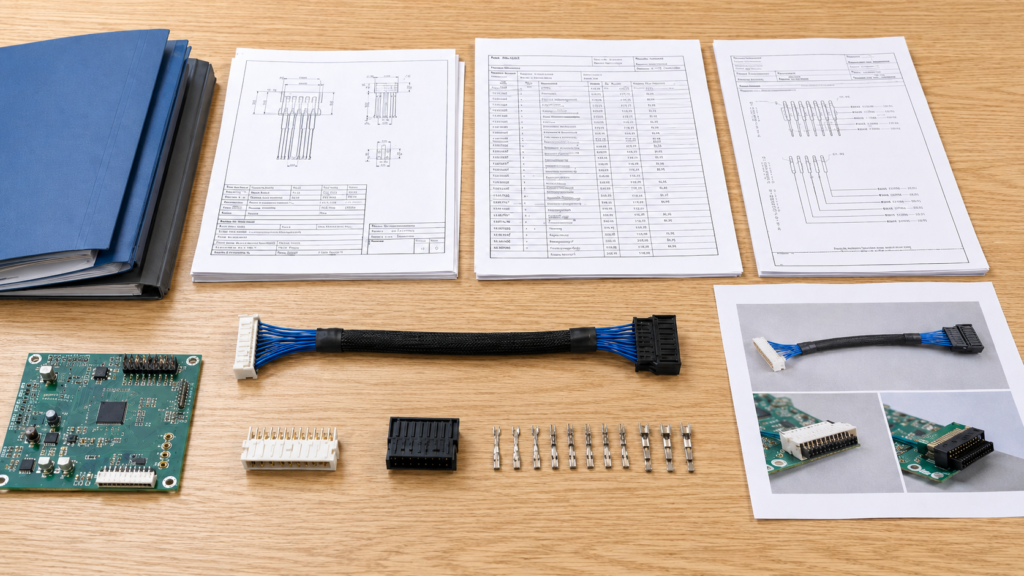
An accurate quote starts with a controlled project package that explains what will be built and how it will be checked. The most useful files are the current cable drawing, BOM, pinout, PCB header reference, revision record, sample photos, and test specification. When some items are unavailable, confirmed facts and temporary assumptions should be listed separately before pricing begins.
| Project File | Minimum Information | Firm-Quote Readiness | Risk if Missing |
| Assembly drawing | Connectors, finished length, branches, labels, protection, tolerances | Dimensions and reference points are unambiguous | Incorrect routing, length, or component position |
| BOM | Manufacturer, part number, description, quantity per assembly | Critical materials and approved alternatives are identified | Material omissions and unexpected sourcing cost |
| Pinout table | Connector cavity, destination, wire color, AWG, signal name | Every circuit can be traced and electrically tested | Reversed polarity, crossed circuits, or unused-pin errors |
| PCB reference | Header model, orientation, pin-one location, installation space | Mating compatibility can be reviewed | Correct cable may not fit the actual board |
| Revision record | Drawing revision, BOM revision, issue date, approval status | All files refer to the same design version | Supplier quotes or builds an obsolete version |
| Photos or sample | Overall assembly, connector close-ups, labels, installation context | Hidden details are supported by written specifications | Visual similarity is mistaken for technical equivalence |
| Test specification | Test items, limits, sampling level, report needs | Test scope and required fixtures are known | Testing cost appears after the first quote |
A project can move forward with incomplete files, but the quotation should state which requirements are confirmed, assumed, excluded, or waiting for customer approval. This simple status control helps engineering and procurement teams understand whether the price is suitable for early budgeting, prototype approval, or an actual production order without mistaking an estimate for a released specification.
Drawing Control
A cable assembly drawing should describe the finished product in a way that engineering, production, quality, and purchasing teams can interpret consistently. It should identify each connector, the finished cable length, measurement reference points, branch dimensions, breakout locations, wire colors, label positions, sleeves, heat-shrink tubing, clips, ferrites, grommets, and any other installed part. Critical dimensions need explicit tolerances, because a general tolerance block may not be suitable for connector position, branch length, or installation clearance.
Measurement points require particular care. A nominal 300 mm assembly can mean housing face to housing face, rear of housing to rear of housing, or cut-wire end to cut-wire end, and each definition changes material consumption and finished inspection. Connector views should also identify the mating face, wire-entry side, latch position, pin-one location, and cable-exit direction. For compact equipment, include the available routing space so the sample does not become electrically correct but mechanically impossible to install.
BOM and Part Numbers
The bill of materials should identify every purchased or manufactured component required for one finished assembly. A description such as four-pin connector may be useful during an early conversation, but it is not enough for a production quotation. The BOM should list the manufacturer, full housing part number, crimp terminal, secondary lock, seal, cavity plug, retainer, backshell, and any customer-controlled option. Similar housings can accept different contacts, and one contact family may have several plating, conductor-range, or packaging versions.
Wire entries should include AWG or cross-sectional area, conductor construction, insulation or jacket material, color, voltage and temperature rating, and the applicable wire style when it is controlled by the design. Small items also belong in the BOM, including heat-shrink tubing, braided sleeve, tape, cable ties, labels, protective caps, bags, cartons, and customer-supplied parts. Marking each item as original-only, approved-equivalent, or subject to approval reveals long-lead materials and minimum-purchase risks before sampling begins.
Pinout and Revision
A pinout should make every electrical connection traceable from one end of the assembly to the other. Each circuit should show the source connector, cavity number, destination, wire color, wire gauge, signal name, polarity, and any special instruction for shields, drain wires, jumpers, or unused positions. Wire color alone is not a strong control method because projects may use repeated colors, striped wires, numbered conductors, or locally approved substitutions. Pin and signal references provide a more reliable basis for assembly and testing.
The drawing, BOM, and pinout must also share compatible revision information. A frequent source of requotation is a drawing at revision B, a BOM at revision A, and a pinout changed in an email without a revision number. The RFQ should state whether each file is released for production, released for prototype, supplied for reference, or still under review. Open issues can be listed separately, allowing the manufacturer to price confirmed requirements without turning an unresolved detail into a silent manufacturing assumption.
Incomplete Files
A project can often start before a complete engineering package exists, provided the available evidence is used carefully. Clear photographs can show the overall assembly, branch structure, latch direction, external protection, labels, and installation context. A useful photo set includes both connector mating faces, wire-entry sides, side profiles, part markings, the PCB header in its installed position, and a scale reference. A physical sample can provide additional information about dimensions, handling, connector fit, and external construction.
Photos and samples still cannot reliably confirm every hidden detail. They may not reveal the terminal part number, conductor construction, exact wire gauge, shielding termination, material grade, electrical rating, or original design revision. When drawings are missing, begin with measured length, connector close-ups, known part numbers, application, voltage and current, target quantity, and required tests. The manufacturer can then identify which items need measurement, datasheet review, electrical mapping, sample disassembly, or prototype validation before issuing a firm production price.

Which Connector and PCB Details Must Be Confirmed?
The complete mating connector system must be identified before pricing can be considered reliable. Confirm the PCB header, wire-side housing, terminal, pitch, circuit count, orientation, keying, locking parts, seals, plating, approved brands, and availability. A connector may look correct while using a different terminal or polarization feature, creating a sample that cannot mate, latch, or carry the intended load.
| Connector Detail | Common Options | What Must Be Verified | Selection Value |
| Pitch | 1.0, 1.25, 2.0, 2.5/2.54, 3.96, 4.2 mm are common families | Exact series and datasheet dimensions | Prevents confusion between similar-looking systems |
| Position count | 2 to 20+ positions depending on connector family | Total cavities and populated circuits | Defines housing, pinout, and test fixture |
| Header orientation | Vertical, right-angle, top-entry, side-entry | PCB mounting and cable-exit direction | Reduces enclosure and routing interference |
| Terminal wire range | Defined by each contact series | AWG, insulation diameter, strand construction | Supports correct crimp and cavity retention |
| Retention | Friction lock, latch, secondary lock, TPA, wedge lock | Mating force and vibration requirements | Changes assembly steps and retention performance |
| Environmental design | Unsealed, protected, sealed | Seal, cavity plug, jacket, mating condition | Controls suitability for moisture and contamination |
| Contact finish | Tin, selective gold, specified plating | Current, signal, cycle life, customer standard | Affects cost, availability, and electrical behavior |
| Supply status | Standard, allocated, obsolete, customer-supplied | Lead time, MOQ, approved alternatives | Affects quotation validity and schedule |
Pitch and circuit count help narrow a connector family, but they do not prove mating compatibility. Exact part numbers or controlled dimensional evidence are still needed because keying, latch geometry, contact design, plating, housing depth, and terminal retention can vary within products that appear almost identical. A sample fit check should be considered when the board-side reference remains uncertain.
Board-Side Header
The PCB header is the best starting point for identifying a board-to-wire connection. Whenever possible, provide the manufacturer and complete part number rather than a description such as 2.0 mm four-pin header. Multiple connector families can share the same pitch and position count while using different polarization ribs, shrouds, latch geometry, contact shapes, or mating depths. The part number may also define mounting orientation, through-hole or surface-mount termination, contact plating, post length, color, keying, and packaging format.
Clarify whether the header is already installed on the customer PCB, must be purchased with the cable, or is included only as a mating reference. When the part number is unknown, provide high-resolution views of the mating face, side profile, board attachment, latch area, markings, and a known dimension. PCB drawings, component purchase records, or enclosure models can also help. Housing color should never be the main identifier because similar colors appear across many unrelated series.
Housing and Terminal Match
The mating housing and crimp terminal are separate engineering decisions. A housing can belong to the correct connector family while still being assembled with the wrong contact. Terminals may differ by conductor range, insulation diameter, plating, material thickness, current rating, sealed or unsealed construction, and reel or loose-piece packaging. The selected contact must fit the cavity, lock in place after insertion, and accept the chosen wire without folding strands or exceeding the insulation-crimp range.
Some connector systems also require a secondary lock, terminal-position assurance device, wedge lock, wire seal, interface seal, cavity plug, retainer, or backshell. These parts add material and assembly work, and they can change insertion sequence, inspection, and rework. For repeat production, reel terminals and controlled applicators often support more consistent processing than loose contacts. Higher-risk projects may also call for first-off crimp approval, crimp-height records, pull-force checks, or cross-section analysis before the production setup is released.
Orientation and Keying
Connector orientation affects both electrical correctness and physical installation. Drawings should identify the mating-face view, wire-entry view, pin-one position, latch side, header orientation, cable-exit direction, nearby PCB components, enclosure clearance, and the first required bend. Words such as left, right, up, and down become ambiguous when the cable, PCB, and drawing are viewed from different sides. A marked image or controlled connector outline is usually safer than relying on directional language alone.
Keying and polarization also need review. Some connector families use multiple key positions to prevent incorrect mating, so a housing with the correct pitch and circuit count may still be incompatible. When several similar connectors appear on one board, labels, colors, unique keying, or different position counts may reduce assembly mistakes. During sample development, a physical connector-fit check can confirm latch engagement, insertion depth, cable direction, and enclosure interference that part-number review alone may not fully reveal.
Original and Alternative Parts
The sourcing policy should state whether original branded components are mandatory or whether approved alternatives may be considered. Original parts may be required because of an approved vendor list, existing qualification, field-service compatibility, warranty controls, internal standards, or established mating-cycle data. Other projects can accept an alternative when dimensional fit, contact design, current capability, resin, plating, keying, terminal retention, and reliability are reviewed rather than assumed.
A lower-priced housing is not automatically equivalent. It may mate physically while using a different terminal, locking feel, contact normal force, or material rating. The RFQ can classify parts as original-only, original-preferred with a separate alternative, approved-equivalent, customer-supplied, or alternative after sample approval. When a connector is obsolete, allocated, or subject to a long procurement cycle, separate options are often more useful than one blended price because each sourcing path carries different cost, lead-time, and approval conditions.

How Should the Wire and Pinout Be Specified?
The wire specification should define conductor size, strand construction, conductor material, insulation, color, electrical load, shielding, and environmental needs. The pinout should map every circuit by connector and cavity number. Finished length, measurement reference points, tolerances, branch positions, and protective parts must also be clear enough for production setup, electrical testing, and final dimensional inspection.
| AWG | Approx. Area | Common Project Use | Quotation Checks |
| 28 AWG | 0.08 mm² | Low-current signals and compact electronics | Terminal fit, voltage drop, flexing |
| 26 AWG | 0.13 mm² | Signals, sensors, low-current control | Insulation diameter and routing space |
| 24 AWG | 0.20 mm² | Control circuits and moderate signal or power | Current, bundle temperature, terminal range |
| 22 AWG | 0.33 mm² | Control power, appliances, industrial signals | Crimp tooling, voltage drop, flexibility |
| 20 AWG | 0.52 mm² | Higher-current internal connections | Contact rating, bend radius, cavity size |
| 18 AWG | 0.82 mm² | Power distribution and equipment wiring | Heat rise, terminal design, strain relief |
| 16 AWG | 1.31 mm² | Higher-current power applications | Connector family, mechanical space, tooling |
Conductor areas are approximate and should be treated as an early selection reference rather than a final current-rating rule. Current suitability depends on ambient temperature, bundle size, duty cycle, conductor length, strand construction, insulation rating, terminal capacity, connector design, allowable voltage drop, and the applicable project specification. The wire and contact should always be reviewed as one electrical and mechanical system.
Conductor and Insulation
Wire gauge should be selected from the complete electrical and mechanical requirement, not from current alone. The manufacturer needs the operating voltage, normal current, peak current, duty cycle, cable length, ambient temperature, bundling condition, and acceptable voltage drop. A conductor that performs well in open air can run warmer when grouped with other energized wires inside a sealed enclosure. The selected wire must also fit the contact, because terminal datasheets usually define both conductor area and insulation-diameter ranges.
Conductor construction changes flexibility and processing. Fine strands can perform better in repeated movement, while coarser strands may be appropriate for stationary equipment, but both require a compatible crimp design. Tinned copper may be selected for solderability, moisture exposure, or customer specifications, yet it is not a universal upgrade. Insulation information can include PVC, PE, XLPE, TPE, TPU, PUR, silicone, or another controlled compound together with temperature rating, voltage rating, abrasion, chemical exposure, flame performance, flexibility, color, and printing requirements.
Pinout Definition
The pinout is the functional map of the assembly and should remove the need for production staff to infer connections from colors or photographs. Each conductor should identify the connector reference, cavity number, viewing direction, destination, wire color, AWG, circuit name, polarity, and any special instruction for a shield, drain wire, jumper, or unused position. Power, ground, communication pairs, sensors, and reserved circuits should be labeled consistently with the PCB schematic and equipment documentation.
The same data should drive the electrical test program. A continuity check that only confirms current flow is not enough if it cannot identify crossed wires, shorts, reversed polarity, open circuits, or incorrect cavity placement. Where several conductors use the same color, numbered markers or printed wires may be required for assembly and field installation. Clear pinout control also makes later revisions easier because engineering teams can compare changed circuits without reinterpreting a photograph or an informal wiring note.
Length and Tolerances
Length should be defined as a finished dimension between visible reference points. Common methods include housing face to housing face, rear of housing to rear of housing, connector shoulder to stripped end, breakout point to connector, or the centerline of one controlled feature to another. A nominal 500 mm cable can vary significantly depending on whether connector bodies are included, so the drawing must show the selected method rather than leaving the inspector to decide.
Tolerances should reflect installation needs. A short internal jumper near fixed PCB components may need tighter control than a long cable routed through a cabinet, but unnecessarily tight tolerances add cutting, assembly, and inspection effort. Critical dimensions can be controlled separately, including main length, branch length, breakout position, strip length, heat-shrink position, label position, exposed conductor, and distance to the first bend. A routing sketch or enclosure image helps determine where precision creates real value and where normal manufacturing variation is acceptable.
Mechanical Protection
Mechanical protection should match the actual handling and service risks. Heat-shrink tubing may insulate a splice, protect a solder joint, secure a label, or reinforce a transition. Braided sleeve can organize conductors and improve abrasion resistance, while corrugated tubing or textile tape may suit larger or more flexible harnesses. Ferrites, clips, grommets, ties, seals, and mounting parts should be shown with controlled positions because small accessories can create significant labor when they require precise placement.
Overmolding should be defined by function rather than appearance alone. It may reduce stress at the connector exit, protect a termination, control cable direction, support sealing, or create a customer-specific external shape. The RFQ should include the available envelope, exit angle, material preference, hardness where controlled, color, surface, logo position, and mating clearance. Custom molds, crimp applicators, assembly fixtures, and electrical test fixtures should be separated from unit pricing, then locked through an approved sample and final drawing before mass production.

Which Application and Quality Requirements Affect the Quote?
Application conditions determine whether the selected connector, terminal, conductor, protection, and test plan are suitable. The RFQ should describe voltage, current, signal type, installation space, temperature, movement, vibration, moisture, chemicals, expected service conditions, acceptance limits, documentation, and target-market needs. Tests should address the real risks of the assembly instead of being added as a generic list after sampling.
| Requirement | Useful Project Data | Typical Verification | Quotation Impact |
| Continuity and miswire | Circuit count and approved pinout | Often a programmed test on finished assemblies | Fixture setup and production test time |
| Short circuit | Allowed and prohibited connections | Included in the electrical test program | Programming and connector fixtures |
| Crimp quality | Terminal, wire size, crimp specification | Crimp height, visual check, pull-force sampling | Applicator setup and quality records |
| Connector fit | Mating header or equipment sample | First article or defined production sampling | Mating parts and inspection labor |
| Insulation or hi-pot | Test voltage, time, leakage limit | Per customer or product requirement | Safety equipment and cycle time |
| Signal performance | Protocol, impedance, frequency, data rate | Project-specific functional or electrical test | Cable structure and specialized fixture |
| Bending durability | Bend angle, load, speed, cycle target | Validation when movement is relevant | Material selection and sample validation |
| Environmental resistance | Temperature, humidity, salt, oil, moisture | Project-specific chamber or material test | Materials, sealing, and documentation |
Test methods and acceptance limits should come from the customer specification, component data, agreed workmanship standard, or approved validation plan. One universal limit cannot be applied to every connector and wire combination because conductor size, terminal geometry, plating, insulation, application voltage, movement, and environmental exposure can change the relevant risk. The quotation should also state the sampling level and required test records.
Electrical and Signal Loads
The manufacturer needs to understand what each circuit carries. For power conductors, provide operating voltage, normal current, peak or startup current, duty cycle, acceptable voltage drop, grounding arrangement, and any fault or protection requirement. Motors, heaters, lamps, solenoids, and capacitive loads can draw more current during startup than during steady operation. Increasing wire size alone does not solve a current problem if the connector contact or PCB header remains the limiting component.
For signal circuits, identify whether the assembly carries an analog sensor, discrete control, digital communication, differential pair, pulse, clock, or data interface. Controlled requirements may include frequency, data rate, characteristic impedance, twisting, shielding, drain-wire termination, and ground reference. A general description such as signal cable is not enough to distinguish a switch line from a noise-sensitive interface. Voltage drop and resistance should be reviewed across the conductor, terminal crimps, connector contacts, splices, and the complete route.
Operating Environment
The same assembly can require very different materials depending on its environment. The RFQ should describe minimum and maximum temperature, storage conditions, humidity, condensation, indoor or outdoor use, dust, water, oil, fuel, cleaning agents, ultraviolet exposure, vibration, shock, repeated bending, torsion, and expected mating cycles. A stationary cable inside office equipment may prioritize compact routing, while an assembly near machinery may need stronger abrasion resistance, locking retention, shielding, oil resistance, or strain relief.
Broad phrases such as waterproof, high temperature, or industrial should be translated into measurable conditions. Sealing depends on the complete mated connector, interface seals, wire seals, cavity plugs, jacket, overmold, assembly process, and test method. Temperature capability depends on materials, current load, and the surrounding enclosure. Installation images or CAD views are useful when the connector sits near a wall, sharp edge, heat source, or moving part because those constraints can change orientation, cable diameter, bend radius, sleeve, and overmold dimensions.
Testing and Acceptance
The quality plan should define what will be tested, how often it will be tested, and which limits apply. For many board-to-wire assemblies, electrical checks include continuity, open circuits, short circuits, miswires, and polarity. Crimp quality may be controlled through approved applicator settings, crimp-height measurements, conductor-brush inspection, insulation support, terminal retention, first-off approval, and pull-force sampling. Acceptance values should come from the contact specification, customer drawing, or agreed workmanship criteria rather than a single generic number.
Additional validation may include insulation resistance, dielectric withstand, contact resistance, voltage drop, insertion and withdrawal force, connector-life, bending, vibration, temperature cycling, salt exposure, or functional testing with customer equipment. The RFQ should state whether testing applies to engineering samples, first articles, each production lot, a defined sample size, or every finished unit. Reporting expectations also matter because raw data, inspection reports, certificates, photographs, lot traceability, and retained samples require different levels of fixture, labor, and document control.
Compliance and Records
Compliance should be defined by the final equipment, application, target market, and customer specification. A cable may use materials that meet a restricted-substance requirement without the complete assembly carrying an independent product approval. The RFQ should separate material declarations, component recognition, workmanship requirements, finished-assembly tests, and end-equipment certification. Possible records include material data, approved wire styles, first-article reports, inspection results, certificates of conformance, and customer-controlled acceptance documents.
Traceability can cover raw-material lots, connector batches, terminal reels, production date, line, operator, test fixture, inspection result, label, serial number, and packaging lot. The required depth should match project risk rather than being added automatically. Third-party testing, external laboratory fees, customer audits, special forms, and documentation preparation should be identified before sampling. Early confirmation is usually less disruptive than changing material, labeling, test fixtures, or inspection records after the design has already been approved.

How Do Commercial Details and Missing Data Affect the Quote?
Technical files define the assembly, while commercial details determine how materials, tooling, labor, testing, packaging, and delivery will be planned. A useful RFQ includes prototype quantity, pilot quantity, production volume, annual forecast, packaging, labels, target dates, and destination. When critical details remain open, the quotation should list its assumptions and clearly state whether it is budgetary, prototype-based, or production-ready.
| Quote Stage | Information Available | Pricing Confidence | Appropriate Use |
| Budgetary estimate | Concept, photos, approximate length and quantity | Low to moderate | Early feasibility and design comparison |
| Prototype quote | Preliminary drawing, connector choice, pinout, sample quantity | Moderate | Sample development and validation |
| Pilot quote | Near-final drawing, BOM, test plan, packaging concept | Moderate to high | Pre-production and process review |
| Production-ready quote | Released files, quantities, tests, packaging, schedule | High within stated validity | Purchase-order and supply planning |
| Requote after revision | Controlled change list and updated files | High when changes are clear | Comparing cost between revisions |
A firm quotation should identify its drawing, BOM, and pinout revisions, validity period, included tooling and testing, material assumptions, packaging scope, freight basis, and any items supplied by the customer. It should also separate one-time engineering or fixture charges from recurring unit cost so later design changes and volume discussions can be reviewed without losing the original pricing logic.
Quantity and Forecast
A custom cable project should not be priced from one quantity alone. Separate engineering samples, validation samples, pilot production, the first production order, regular release quantities, and estimated annual usage. A five-piece sample build includes engineering review, setup, programming, crimp validation, fixture preparation, and manual handling that cannot be distributed across thousands of units. Sample pricing therefore should not be treated as a simple preview of the later production unit price.
Production quantity affects connector packaging multiples, terminal reel requirements, custom wire minimums, tooling utilization, labor method, and material purchasing. A forecast can be given as a range when demand is still developing. For example, a project may begin with 20 samples, move to a 300-piece pilot, and then expect quarterly releases of 2,000 to 5,000 assemblies. That information supports realistic price breaks and planning without pretending that an early forecast is a binding commitment.
Packaging and Labeling
Packaging becomes part of the product specification when the assembly must enter a controlled warehouse, production line, service network, distribution channel, or retail program. The RFQ should state whether cables are bulk packed, individually bagged, coiled, tied, placed in trays, separated by part number, or supplied as a kit. Connector caps, dividers, foam, or a minimum coil diameter may be needed when latches, seals, terminals, or overmolded areas could be damaged during transport.
Label requirements may include the customer part number, revision, barcode, lot, serial number, wire number, installation direction, date code, country-of-origin wording, and handling information. The customer should provide approved artwork, barcode format, material, size, and position. For multi-SKU orders, define the quantity per bag, inner carton, master carton, and pallet, along with rules for mixed cartons and SKU separation. The phrase standard export packaging is too vague to calculate labor, protection, and error-control requirements accurately.
Timeline and Logistics
A realistic schedule separates the RFQ deadline, drawing release, sample target, sample approval, pilot build, mass-production completion, shipment date, and required arrival date. Arrival at the customer site is not the same as factory completion, especially when international transport, customs clearance, local delivery, and holiday schedules are involved. The project team should provide destination country and city, preferred shipping method, Incoterm where applicable, partial-shipment policy, carton or pallet limits, consolidation needs, and required export documents.
Connector availability is often the critical path. A common housing may be available while the matching terminal, seal, secondary lock, or approved plating option has a longer purchasing cycle. Custom wire, tooling, overmolding, test fixtures, and printed packaging can also influence timing. Starting a sample before connector, pinout, and length confirmation may appear faster, but a rebuild can erase that advantage. A short engineering-confirmation stage usually creates a more reliable path from quotation to approved sample and production.
Start with a Controlled RFQ
Missing information does not always prevent a quotation, but it changes what the quotation can be used for. Common open items include an unidentified PCB header, unknown terminal, incomplete pinout, unclear connector view, approximate length, undefined tolerance, missing electrical load, unconfirmed material, undeveloped packaging, and unspecified test limits. Each item should be marked as customer confirmation required, manufacturer proposal required, sample needed, datasheet review needed, prototype validation required, or excluded from the current price.
Cablivo supports board-to-wire cable assembly projects from requirement review, drawing and BOM checking, connector confirmation, material discussion, prototype development, sample revision, mass-production preparation, testing, labeling, packaging, and export coordination. The Shenzhen-based manufacturing organization has 18 years of industry experience, more than 20,000 square meters of factory space, a team of more than 1,500 people, and three manufacturing bases. To begin an engineering review, send the files already available, including the drawing, BOM, connector model, PCB header reference, pinout, cable length, AWG, application, quantity, test requirements, packaging plan, and target schedule.
End of Article



