 Skip to content


An industrial automation wire harness can look deceptively simple on a quotation sheet. A few connectors, several colored wires, some labels and perhaps a protective sleeve may appear easy to price. In practice, one missing pinout, an unclear branch length or an undisclosed movement condition can change the required cable, terminals, protection, tooling, assembly process, testing method and final cost.
The real challenge is not asking a manufacturer, “How much is this harness?” It is defining exactly what the finished harness needs to do inside the equipment.
To quote an industrial automation wire harness accurately, a manufacturer normally needs a drawing or reference sample, BOM, connector and terminal part numbers, wire specifications, pinout, dimensions, application environment, movement conditions, protection requirements, testing criteria, prototype and production quantities, packaging instructions and delivery expectations. Complete information reduces assumptions and makes the quotation more dependable.
A complete RFQ does more than help calculate a unit price. It creates a shared technical reference for engineering review, sample development, installation validation, mass production, inspection, packaging and future repeat orders.
Consider a common situation. A purchasing team sends a harness photograph and requests a quick price. During sample development, the manufacturer discovers that the cable must operate inside a drag chain, resist coolant, use a specified imported connector, maintain a controlled bend radius and pass a customer-defined electrical test. The original estimate may no longer apply—not because the manufacturer priced carelessly, but because the original request described only the visible product and not its real operating conditions.
The purpose of a strong quotation package is to make sure every supplier is pricing the same product, under the same conditions, with the same quality expectations.
| Information Group | What to Provide | Why It Affects the Quote |
| Technical files | Drawing, wiring diagram, BOM, sample or photographs | Defines the physical and material scope |
| Connections | Connector, terminal, pinout and mating details | Prevents component and wiring assumptions |
| Wire construction | AWG, conductor, insulation, color and rating | Determines material and processing requirements |
| Mechanical layout | Overall length, branches, breakouts and tolerances | Determines wire consumption and assembly labor |
| Application | Control cabinet, machine, moving assembly or sensor system | Identifies routing and environmental requirements |
| Protection | Shielding, sleeve, conduit, sealing or overmolding | Changes materials, tooling and production steps |
| Quality | Continuity, insulation, hi-pot, pull-force or functional tests | Determines inspection equipment and test time |
| Commercial scope | Samples, order quantity, forecast and number of SKUs | Influences sourcing, setup and unit pricing |
| Delivery | Packaging, labels, destination and required schedule | Affects packing and shipment preparation |
What Files Are Needed for a Quote?
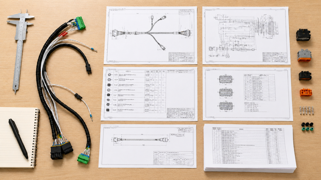
An accurate quotation normally begins with a controlled information package containing a drawing, wiring diagram, BOM, pinout, revision status, application details and target quantity. A physical sample or clear photographs can support an initial review, but a production-ready price usually requires missing dimensions, materials, electrical connections and acceptance criteria to be confirmed.
Each file answers a different question. A drawing explains the harness geometry. A wiring diagram defines electrical relationships. A BOM identifies the materials. A pinout shows exactly how the circuits connect. A physical sample reveals construction details that may not be obvious on a drawing.
Problems arise when these references conflict. A BOM may list one connector while the sample uses another. A drawing may show an outdated branch length. A label file may belong to the previous revision. Engineering review should identify these differences before the manufacturer confirms material cost, tooling or sample arrangements.
Providing several references is therefore helpful, but only when the customer clearly identifies which revision controls the quotation.
Drawing and Layout
A harness drawing should show more than one overall dimension. It needs to explain how the finished assembly will fit, route and connect inside the equipment.
Useful dimensions include the main trunk length, individual branch lengths, breakout positions, connector orientation, cable exit direction, sleeve coverage, splice positions, clamp points and label locations.
Measurement points must be clearly defined. For example, a 600 mm harness length could be measured from connector face to connector face, housing end to housing end, rear cable exit to rear cable exit or by unfinished wire cut length. Those methods do not necessarily produce the same finished assembly.
Tolerances should reflect actual installation needs. A short sensor lead installed between two fixed components may require tighter length control than a long harness routed loosely through a cabinet. Specifying an unnecessarily tight tolerance can increase inspection work and rejection risk without creating practical value.
For branched harnesses, a flat layout drawing or harness-board reference helps the manufacturer understand how the branches relate to one another. Equipment installation photographs are also valuable when routing space is limited or when connectors must pass through narrow openings.
| Drawing Item | Practical Information to Include | Main Review Point | Quotation Impact |
| Overall length | Defined start and end measurement points | Finished length versus cut length | Material consumption |
| Branch length | Dimension from breakout to connector datum | Whether each branch reaches naturally | Wire and assembly labor |
| Length tolerance | Functional allowable variation | Whether tolerance is realistic | Inspection time and scrap risk |
| Breakout position | Distance from a fixed datum | Routing and branch direction | Fixture and assembly method |
| Connector orientation | Key position, clocking and exit direction | Mating and installation clearance | Sample review and tooling |
| Sleeve coverage | Start, stop and overlap positions | Protection at transitions | Material and processing |
| Label position | Distance from connector or branch | Visibility after installation | Labeling and repeatability |
BOM and Part Numbers
The BOM should identify every component required to produce one complete harness. This includes the wire or multicore cable, connector housings, terminals, contacts, seals, backshells, wedges, secondary locks, ferrules, lugs, sleeves, braided protection, conduit, heat-shrink tubing, labels, clips, cable ties and molded parts.
Descriptions such as “four-pin waterproof connector” are normally too broad for dependable pricing. Connectors with similar appearances may use different terminal families, coding, sealing components, contact plating or mating geometry.
Exact manufacturer part numbers reduce the risk of quoting an incorrect component. The BOM should also show the quantity of each component used in one harness.
Sourcing responsibility needs to be clear. If the customer supplies a connector, the quotation should identify the expected supplied quantity, spare allowance and incoming inspection responsibility. If the manufacturer sources it, availability, minimum purchase quantity and lead time must be reviewed.
Approved alternatives also need a clear rule. “Equivalent accepted” may mean functionally similar, dimensionally interchangeable or fully approved by the customer’s engineering team. Those are different requirements.
Pinout and Wiring Information
The pinout defines how every electrical path is connected. It should identify connector designations, cavity or pin numbers, wire numbers, colors, gauges, signal names, polarity, splice points and shield terminations.
The viewing direction of every connector must be labeled. A pin diagram shown from the mating face can appear reversed when interpreted from the wire-entry side. This is a frequent cause of sample errors, particularly when the drawing contains only a connector outline and numbered cavities.
For branched harnesses, the wiring table should allow the manufacturer to trace each conductor from its source through any splice or breakout to its final destination.
Hidden splices should be shown rather than explained only in an email. The splice method, location, insulation and protection may change the harness diameter and assembly process.
The pinout also becomes the reference for electrical testing. A requirement such as “100% continuity tested” is incomplete unless the correct connection map is available. The test fixture must know which paths should be connected, which should remain isolated and whether polarity or resistance limits apply.
Revision Control
Every file in the RFQ package should display a revision number, issue date or other controlled identifier. The drawing, BOM, pinout and label files should all refer to the same product version.
Small revisions can have a measurable price effect. Increasing one branch by 100 mm changes material usage. Changing an unsealed terminal to a sealed version adds components and processing. Increasing a conductor from 22 AWG to 18 AWG may require a different terminal, applicator and connector seal.
A short change log makes engineering review faster. Statements such as “J3 connector changed,” “Branch B extended,” “Wire label position moved,” or “Shield termination revised” are more useful than sending a replacement file without identifying the differences.
The quotation should reference the exact revision being priced.
After prototype approval, the approved sample, final drawing, final BOM, label files and confirmed testing requirements should become the production reference. This reduces the risk of purchasing materials from one revision while production follows another.

Which Electrical Details Must Be Confirmed?
Electrical details must define what every conductor carries, how each circuit connects and what performance the finished harness must achieve. Wire gauge, conductor construction, insulation, voltage, current, connector and terminal models, pinout, grounding, shielding and communication requirements should be confirmed before a firm quotation is issued.
Two harnesses can look almost identical while having very different electrical requirements. A harness carrying sensor signals does not have the same design priorities as a motor power harness, encoder cable, safety circuit or industrial communication assembly.
The quotation should therefore distinguish between power, control, analog signal, digital signal, communication and grounding circuits. This helps the manufacturer review conductor size, cable construction, shielding, pair twisting, separation and testing requirements.
Wire and Cable Specifications
Wire gauge alone does not fully define a conductor. Two wires with the same AWG can have different strand counts, insulation thicknesses, temperature ratings, flexibility and finished diameters.
For each circuit, provide the AWG or metric cross-section, conductor material, stranding, insulation type, color and required electrical rating. The actual current, voltage, run length and operating conditions should support the selection.
Signal circuits often use smaller conductors, while motors, solenoids, heaters and power-distribution circuits may require larger sizes. The appropriate gauge depends on current, allowable voltage drop, conductor length, bundling, ambient temperature and the equipment specification.
Where movement matters, conductor stranding and jacket construction become especially important. A wire that feels flexible during installation is not automatically designed for repeated drag-chain or robotic motion.
| Circuit Type | Illustrative Wire Range | Important Specification | Main Quotation Concern |
| Low-level sensor signal | 26–22 AWG | Noise control and flexibility | Shielding and termination |
| PLC digital I/O | 24–18 AWG | Current and installation method | Wire count and identification |
| Solenoid or valve power | 20–16 AWG | Inrush current and voltage drop | Terminal and conductor size |
| Motor or higher-current load | 16–10 AWG or larger | Current, temperature and run length | Cable diameter and processing |
| Protective earth | Project-defined | Grounding requirement and color | Terminal type and pull force |
| Industrial communication | Protocol-specific cable | Impedance, twisting and shielding | Cable construction and testing |
These ranges are practical examples rather than universal design rules. Final conductor selection should follow the equipment specification and actual electrical load.
Connectors and Terminals
The connector specification should include the manufacturer, product family, exact housing number, gender, pin count, coding, keying, seal, backshell, secondary lock and mating connector.
The terminal or contact part number is equally important. One housing may accept several terminals intended for different wire gauges, insulation diameters or plating requirements. Quoting the correct housing with the wrong contact can still produce an unusable assembly.
For circular automation connectors, descriptions such as “M12 connector” are incomplete. The quotation may also require the coding, number of contacts, male or female configuration, straight or right-angle body, molded or field-wireable construction and cable exit direction.
When the machine already contains the mating connector, provide its exact number or a clear front-facing photograph. Connector fit should be confirmed during sampling rather than assumed from appearance.
Component availability can also affect prototype and production pricing. An imported connector with a high minimum purchase quantity may be practical for regular production but expensive for a small sample batch. Approved alternatives can be discussed, but substitutions should not be made without technical confirmation.
Pinout and Circuit Function
A useful pinout does more than connect Pin 1 to Pin 1. It identifies the purpose of each circuit so that wire, shielding and test requirements can be reviewed properly.
The connection table should include the source connector, source pin, destination connector, destination pin, signal name, wire gauge, wire color and any special termination instruction.
Polarity-sensitive circuits must be marked clearly.
Grounding also requires careful definition. Signal ground, power return, chassis ground, protective earth and shield drain are not automatically interchangeable. Their termination points should be determined by the equipment design.
Splices must be documented. One power conductor may divide into several branches, or multiple return conductors may combine at one location. The joining method, insulation and protection can affect bundle diameter, assembly labor and test planning.
When circuit functions are known, engineering review can identify conflicts before samples are built—for example, an oversized conductor paired with a small terminal or a noise-sensitive signal routed without the required shielding.
Shielding and Communication
Shielded construction can change the cable, termination method, connector components and processing time.
State whether the project requires foil shielding, braided shielding, individual-pair shielding, overall shielding or a combined structure. Foil can provide broad coverage with a relatively small diameter, while braid may provide stronger mechanical protection and lower electrical resistance.
The practical result depends heavily on termination. A twisted drain wire attached to one pin is not equivalent to a full circumferential shield connection to a conductive backshell.
Define whether the shield should be connected at one end, both ends or through a specific grounding component. The correct arrangement depends on the overall system and should not be guessed by the harness manufacturer.
For industrial Ethernet, EtherCAT, PROFINET, CAN, RS-485, encoder feedback or other communication circuits, provide the required cable type, performance requirement or approved cable part number.
Continuity alone may not verify impedance, pair balance, attenuation or communication performance. If protocol or signal testing is required, identify the test method, limits, fixture and reporting expectations during quotation.

What Automation Conditions Affect the Design?
Automation conditions determine whether a harness is a simple static interconnect or a component exposed to continuous mechanical and environmental stress. The RFQ should explain movement, bend radius, torsion, routing, vibration, temperature, oil, coolant, dust, moisture, electromagnetic interference and installation space so that suitable materials and protective structures can be evaluated.
The same connector and pinout may require very different construction depending on the installation.
A short harness inside a protected control cabinet may use conventional wiring and simple bundle protection. A robot-arm harness may need high-flex cable, controlled torsion, strain relief and carefully defined clamping positions. A sensor cable near machining equipment may need abrasion protection and resistance to coolant exposure.
Terms such as “industrial grade,” “flexible” and “waterproof” are too broad by themselves. The quotation needs measurable or observable operating conditions.
Static and Moving Applications
The first question is whether the harness remains fixed after installation or moves during each machine cycle.
A static harness inside a cabinet may need flexibility only during installation and maintenance. A harness inside a cable carrier may bend repeatedly over the entire service life. A robot-arm cable may experience bending and torsion at the same time.
Describe the movement type, travel distance, speed, acceleration, bending plane and expected cycle requirement. For torsional movement, include the approximate rotation angle and the cable length over which the torsion occurs.
For cable carriers, include the available carrier space, travel length, cable orientation and minimum bend radius.
A flexible cable is not automatically a continuous-flex cable. A soft jacket may feel flexible in the hand but still be unsuitable for repeated dynamic operation.
| Application | Movement Pattern | General Starting Bend Radius* | Main Design Concern |
| Control cabinet | Static after installation | 4–6 × cable OD | Routing and terminal strain |
| Hinged machine section | Occasional bending | 6–10 × cable OD | Localized fatigue |
| Cable carrier | Repeated linear bending | 7.5–15 × cable OD | Flex life and carrier filling |
| Robot arm | Bending and torsion | Cable-specific | Torsion and stress distribution |
| Moving sensor | Short repeated stroke | Cable-specific | Exit protection and clamping |
| Portable service lead | Irregular manual movement | Application-specific | Abrasion and handling |
*These figures are general engineering references, not guaranteed limits. The selected cable specification and actual operating conditions should determine the final bend radius.
Dimensions and Routing
A harness can be electrically correct and still fail during installation if the dimensions or connector orientation do not match the machine.
Show the actual routing path rather than only the straight-line distance between two devices. Include clamps, conduits, panel openings, moving joints, service loops and restricted areas.
A branch that is too short can place continuous load on the connector. A branch that is too long may create an uncontrolled loop or interfere with moving machine parts.
A large splice positioned inside a narrow conduit may prevent the harness from being installed, even if every length is correct.
Connector clocking is particularly important for right-angle connectors and keyed circular interfaces. A 90-degree orientation error may force the cable toward a machine frame instead of the intended routing channel.
Where space is limited, state the maximum bundle diameter. Sleeving, conduit, heat shrink and hidden splices can make the finished assembly larger than the combined wire diameters suggest.
Whenever possible, the prototype should be checked inside the real equipment. Installation feedback often reveals issues that cannot be found by inspecting the harness only on a workbench.
Environment and Materials
Environmental requirements should be described using real operating conditions.
Identify operating and storage temperatures, humidity, vibration, dust, water exposure, washdown, oil, coolant, cleaning chemicals, UV exposure and indoor or outdoor use.
If only one section of the harness enters a harsh environment, mark that section on the drawing. The entire assembly may not need the same material or protection.
PVC is widely used for many static industrial applications. PUR is often discussed where abrasion, oil exposure or repeated movement may be important. TPE can provide flexibility and a softer feel. Silicone may be considered where unusual flexibility or temperature performance is needed.
Material suitability depends on the exact compound, construction and validation requirement. “Oil resistant” is not a universal condition. Hydraulic oil, cutting coolant, lubricant and cleaning chemicals may affect materials differently.
Where exposure is critical, provide the chemical name, concentration, temperature and contact duration.
The same caution applies to water protection. A sealed connector, appropriate jacket, cable-entry seal and overmolded transition may all contribute, but the required protection level and test condition must be defined.
Protection and Strain Relief
Protective components should be selected according to the actual failure risk.
Braided sleeving can organize conductors and reduce abrasion. Corrugated conduit can provide stronger mechanical protection but adds diameter and may reduce flexibility. Heat-shrink tubing can insulate joints, secure labels or reinforce transitions.
Grommets protect cables passing through sheet-metal openings. Clips and clamps control routing and help prevent the connector termination from carrying mechanical load.
Strain relief is especially important near connectors, branch points and moving exits. Repeated bending or pulling should not be transferred directly to the terminal crimp or solder joint.
Overmolding can create a controlled cable exit, support strain relief, protect the connector transition and provide a repeatable external shape. It may also contribute to sealing when used with an appropriate connector and structure.
However, overmolding can require mold development, dimensional review and sample approval. The quotation should define the material, coverage length, color, exit angle, shape and available installation space.
Protection should not be added only because it looks robust. Every sleeve, conduit or molded feature increases cost, processing time and harness diameter. The best structure is the one that addresses the real application risk without making installation more difficult.

Which Quality Requirements Must Be Included?
Quality requirements should define what will be inspected, how it will be tested and what result counts as acceptable. Continuity, pinout, insulation, hi-pot, pull-force, connector-fit, dimensional, visual, labeling and functional tests may be required depending on the application. The testing scope should be agreed before quotation because fixtures, inspection time and reporting requirements can affect cost.
“High quality” is not an acceptance criterion. “100% tested” is also incomplete unless the test method and pass limits are defined.
The quality plan should reflect the actual project risk. A simple cabinet harness may need continuity and visual inspection. A power, safety or communication harness may require additional electrical, mechanical or functional verification.
Electrical Testing
Continuity testing verifies that every intended electrical path is complete. Open- and short-circuit testing checks for broken circuits and unintended connections. Pinout verification compares the finished harness with the approved connection table.
For many custom harness projects, testing every unit for continuity and correct wiring is a practical production requirement. The test must still be based on a controlled pinout.
Insulation resistance and hi-pot testing may be required for power circuits or applications with defined electrical-safety requirements. The test voltage, duration, leakage limit and circuit grouping should be provided.
Project-defined insulation-resistance tests may use values such as 250 or 500 VDC, while hi-pot requirements can range from several hundred volts to more than 1,000 VAC. These are not universal defaults. The correct conditions depend on the working voltage, insulation system and applicable equipment specification.
| Test | What It Checks | Information Required | Typical Decision Point |
| Continuity | Intended circuit is complete | Approved pinout | Commonly applied to every unit |
| Short-circuit check | Unwanted connections | Isolation map | Commonly included with continuity |
| Polarity | Positive and negative routing | Circuit definition | Required for directional circuits |
| Insulation resistance | Electrical isolation | Voltage and minimum resistance | Project-specific |
| Hi-pot | Dielectric withstand | Voltage, duration and leakage limit | Higher-risk electrical projects |
| Functional test | Operation under simulated conditions | Fixture and pass criteria | Equipment-specific |
| Communication test | Signal or protocol performance | Cable specification and test limits | Industrial network projects |
Mechanical Testing
Mechanical tests evaluate whether terminals, connectors and protective structures can withstand handling and operation.
Terminal pull-force testing is commonly used to review crimp integrity. The acceptance value depends on the terminal, wire gauge, conductor construction and applicable specification. One pull-force value should not be applied to every wire and terminal combination.
Connector-fit checks confirm that the correct mating geometry, keying and locking features have been used. For sealed connectors, inspection may also include terminal seating, seal position and secondary-lock engagement.
Bending or swing testing can help evaluate repeated movement, but the setup needs to resemble the intended stress. Bend radius, angle, applied load, speed and cycle count influence the result.
A cable passing a simple workbench bend test does not prove that it will survive inside a robot or cable carrier.
Overmolded assemblies may require pull, flex, dimensional and appearance checks around the cable exit. Mechanical testing should be selected according to the failure mode the project needs to control, not simply added to make the inspection list appear longer.
Labels and Traceability
Labels are functional parts of an automation harness, especially in systems containing many similar connectors and branches.
Specify the label content, material, size, color, print method, orientation and exact position. Common information includes wire number, connector code, part number, revision, serial number, lot number, barcode or installation direction.
The label position should be reviewed in the actual routing environment. A label hidden under a clamp or inside conduit may follow the drawing but still be useless to the installation technician.
Traceability can range from a simple batch code to a system that links a finished harness with material lots, production dates and test records. The required level depends on the project and should be stated during quotation.
For repeat orders, approved label files must be controlled with the product revision. Labels should not be recreated manually from photographs.
Packaging labels require the same care. A correct harness packed under the wrong SKU can create receiving and production-line problems even when the product passes every electrical test.
Standards and Acceptance
If a workmanship or acceptance standard applies, identify it in the RFQ. IPC/WHMA-A-620 is commonly referenced for cable and wire harness assembly workmanship, but the applicable revision, product class and customer-specific requirements should be confirmed.
A workmanship standard does not replace the drawing, BOM, pinout or electrical specification. It provides acceptance criteria for manufacturing details, while the customer documents define what needs to be manufactured.
Target-market requirements should also be separated from general product claims. Material declarations, restricted-substance requirements, flammability expectations, first-article records, inspection reports or test documentation may be needed depending on the equipment and destination.
Do not assume that every harness automatically carries every certification associated with the completed machine.
The quotation should state which inspections and documents are included. If material certificates, first-article reports, serialized test results or shipment inspection records are required, the format and frequency should be confirmed before production.

How Do Quantity and Project Terms Affect Pricing?
Pricing depends on more than the material used in one harness. Prototype quantity, production volume, annual forecast, component availability, tooling, testing, packaging, delivery schedule and number of SKUs can all affect the quotation. A useful RFQ separates sample, pilot and production requirements so one-time development costs and recurring unit prices can be evaluated clearly.
A prototype quotation and a production quotation answer different questions.
Prototype pricing may include engineering review, low-volume material purchasing, manual setup and sample-specific testing. Production pricing assumes an approved design, stable BOM, repeatable process and defined order quantity.
A request for “your best price” does not provide enough information to select the right purchasing or manufacturing approach.
Sample and Production Quantities
Provide separate quantities for engineering samples, validation, pilot production, the first production order and estimated annual demand.
A request for five prototypes is priced differently from a recurring order of 2,000 assemblies. Prototype production often involves manual preparation, engineering review, small material purchases and setup costs spread across very few units.
A useful quantity statement might read:
“Five samples for installation validation, 500 pieces after approval and estimated quarterly releases of 1,500 pieces.”
This gives the manufacturer a basis for material sourcing and process planning without treating the forecast as a fixed purchasing commitment.
When multiple SKUs share connectors, wires or packaging materials, provide a complete SKU matrix. Combined demand may support purchasing efficiency, but every difference in pinout, length, color or label still requires separate production control.
For many Cablivo custom cable and wire harness projects, MOQ starts from 500 pieces. The final MOQ depends on the connector, cable construction, material, overmolding requirement, tooling, packaging plan and order quantity.
| Project Stage | Illustrative Quantity | Main Cost Drivers | Useful Customer Information |
| Engineering sample | 1–10 pieces | Setup, manual work and small material purchases | Critical dimensions and validation goal |
| Validation batch | 10–50 pieces | Revision control and inspection | Equipment installation feedback |
| Pilot production | 50–200 pieces | Process stabilization | Expected production method |
| Initial production | 500+ pieces | Material purchasing and scheduling | Approved sample and final BOM |
| Repeat release | Project-defined | Component planning and consistency | Release frequency |
| Annual forecast | Estimated total | Tooling and sourcing strategy | SKU mix and expected demand |
These ranges are examples for project planning rather than fixed industry rules.
Tooling and Development
Not every wire harness requires custom tooling. Standard cutting, stripping, crimping, soldering and assembly equipment may be sufficient for a straightforward design.
More complex products may require a harness board, assembly fixture, terminal applicator, overmolding tool, electrical test fixture or dimensional gauge.
A form board can help control branch position and finished dimensions. A dedicated tester can reduce wiring risk in a high-pin-count assembly. An overmolding tool can produce a repeatable connector shape and strain-relief profile.
The quotation should separate one-time engineering or tooling charges from the recurring unit price whenever possible. This makes it easier to understand how project cost changes after the first production run.
Tool ownership, storage, maintenance and modification responsibility should be discussed before ordering. A later connector or cable-exit change may require tool modification or replacement.
Sample timing should be confirmed after reviewing the product structure, connector availability, material preparation, tooling and testing requirements. A simple harness made from available parts and a molded multi-connector assembly should not be expected to follow the same development schedule.
Packaging and Delivery
Packaging protects the harness, separates SKUs and helps the receiving team identify the correct product.
State whether the harness should be bulk packed, individually bagged, coiled, tied, placed in a tray or supplied as part of an installation kit.
Define whether connector caps, foam, partitions, antistatic materials or moisture protection are required.
Coiling instructions are particularly important for larger or movement-rated cables. A coil that is too tight may place unnecessary stress on the cable before it is installed. Where appropriate, specify the minimum coil diameter or allowable bend radius.
For multi-SKU orders, submit approved barcode data, label templates, inner-box quantities, master-carton quantities and carton-mark requirements. The quotation should include the labor needed to separate, label and inspect each variant.
Delivery expectations should distinguish between sample completion, production completion, shipment departure and arrival at the destination. These are different milestones.
The shipping destination can also affect carton construction, palletization and export-document preparation. Packaging and logistics details are easier to control when they are included during quotation rather than added after production.
Cost and Requotation Control
The most effective way to reduce price changes is to submit one consistent RFQ package and require the quotation to reference it.
The drawing, BOM, pinout, quantity, testing plan and packaging instructions should use the same product number and revision.
Separate mandatory requirements from optional preferences. For example, “Specified keyed connector required” is a fixed condition, while “PUR or TPE jacket—manufacturer to propose” remains open for engineering evaluation.
Ask the quotation to state its assumptions, exclusions, tooling charges, connector brands, testing scope, packaging basis and validity period.
Two prices cannot be compared fairly when one includes a test fixture and individual packaging while another assumes basic continuity testing and bulk packing.
After the sample is approved, freeze the final drawing, BOM, pinout, label file and testing plan. Changes made after approval should be reviewed for their effect on price, tooling, existing inventory and delivery.
A controlled RFQ cannot prevent every technical question. It ensures that the important questions are discovered before they become sample failures or production problems.
Conclusion
An accurate automation wire harness quotation is created by removing uncertainty—not by adding more sales language to an inquiry.
The manufacturer needs to understand five connected areas:
- What must be manufactured
- How every circuit must connect
- Where and how the harness will operate
- How quality will be inspected
- What quantities, packaging and delivery terms apply
When the drawing, BOM, pinout, application conditions, quality requirements and commercial information agree with one another, the manufacturer can evaluate materials, components, labor, tooling, testing and production planning with fewer assumptions.
Cablivo is the overseas-facing website brand of Shenzhen Tianxiaowei Electronics Co., Ltd., a Shenzhen-based custom cable, wire harness and cable assembly manufacturer. The company supports overseas projects through requirement review, drawing and BOM review, connector confirmation, material selection, sample development, mass production, testing, labeling, packaging and shipment coordination.
To request a custom automation wire harness quotation, prepare as much of the following information as possible:
- Harness drawing or sample photographs
- BOM and specified component part numbers
- Connector and terminal information
- Pinout or wiring table
- Wire gauge and cable construction
- Overall and branch lengths
- Application and installation conditions
- Movement and environmental requirements
- Testing and inspection criteria
- Sample and production quantities
- Packaging and labeling requirements
- Target schedule and shipping destination
Incomplete information does not always prevent an initial engineering review. It does, however, mean that assumptions must be identified and confirmed before a final production quotation can be considered reliable.
Send your drawing, sample photographs, BOM, connector details and target quantity to Cablivo to begin an engineering review for your custom automation wire harness project.



