 Skip to content


A machine vision wire harness may look like a collection of cables, connectors, labels and protective parts, but its actual job can be much more demanding. One assembly may carry camera power, high-speed image data, trigger signals, encoder feedback, lighting control, digital I/O and grounding through a machine filled with motors, drives, moving axes, heat, vibration and electromagnetic noise. An accurate quotation therefore cannot be based only on cable length, connector photos or a short message asking for the lowest unit price.
To quote a custom wire harness for a machine vision system accurately, the manufacturer needs the assembly drawing or reference sample, BOM, connector models, pinout, wire specifications, interface standard, voltage and current, data rate, finished lengths, motion profile, installation environment, shielding and grounding requirements, test plan, quantities, packaging, labeling and target schedule.
These details allow engineering and procurement teams to separate material cost from connector sourcing, tooling, assembly, validation and production cost. They also prevent an inexpensive preliminary quotation from changing after the supplier discovers that the assembly needs controlled-impedance cable, imported components, continuous-flex construction, 360-degree shield termination, custom overmolding or specialized signal validation.
Consider a harness that powers a camera and transfers images correctly while lying straight on a laboratory bench. After installation beside a servo drive and inside a fast-moving cable carrier, the same system begins losing frames during production. The wiring diagram was technically correct, yet the cable structure, shielding, motion rating and installed bend radius were never defined. A useful RFQ closes these gaps before the project reaches the machine.
What Project Files Are Needed for the RFQ?
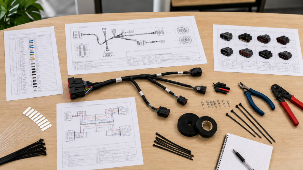
An accurate RFQ should include a controlled assembly drawing, wiring diagram, pinout, BOM, connector part numbers, cable specifications, application details, target quantity and revision status. When formal drawings are incomplete, sample photographs and known operating conditions can support an initial review, but assumptions should be recorded and resolved before the final quotation, sample specification and production documents are approved.
| RFQ document | Minimum information required | What it controls | Common risk when missing |
| Assembly drawing | Finished lengths, branches, connector direction, protection and tolerances | Material usage, routing and assembly process | Harness connects correctly but does not fit |
| Wiring diagram | Circuit connections, signal names, returns and shield paths | Electrical architecture | Crossed circuits or missing returns |
| Pinout table | Pin number, function, color, AWG and destination | Wiring and electrical testing | Mirrored or incorrectly assigned pins |
| BOM | Manufacturer part numbers, quantities, materials and approved alternatives | Sourcing, cost and lead time | Wrong connector or unplanned purchase minimum |
| Sample photographs | Connector faces, markings, labels, branches and protective parts | Preliminary identification | Hidden structural details remain unknown |
| Revision record | Drawing version, change history and approval status | Configuration control | An obsolete design reaches sampling or production |
Controlled Drawings
The assembly drawing should describe the finished harness as it will be installed rather than showing two connectors joined by a simple line. It should define overall length, branch locations, breakout lengths, connector orientation, exposed wire, sleeves, conduit, heat-shrink tubing, overmolding, labels, clamps and critical tolerances. A routing sketch or marked machine image can be included when the harness passes through restricted spaces or moving equipment.
Every dimension needs a clear reference point. A length measured between connector mating faces is different from a dimension measured between overmold shoulders, backshell exits or terminal tips. The drawing should indicate which surfaces or points are used so the manufacturer does not add or subtract connector and overmold lengths incorrectly. Critical branch and connector locations should receive tighter tolerances than non-critical free cable sections.
Applying a very tight tolerance to every dimension can increase inspection time and production cost without improving machine performance. Tolerances should reflect how the harness is installed. Connector positions, panel entries, fixed clamps and compact camera enclosures may need close control, while an unrestricted cabinet section can usually accept a wider length range without creating risk.
The drawing should also include a part number, revision, release date and approval status. If engineering sends Revision C while procurement requests quotations from Revision B, suppliers may appear to offer different prices even though they are quoting different assemblies. Controlled documentation keeps quotation, prototype, sample revision and mass production tied to the same approved design.
Cablivo’s documented engineering scope includes drawing review, sample review, BOM review, connector confirmation, wire-sequence confirmation, pinout review, material selection, DFM feedback, prototype development, sample revision and production preparation.
BOM and Connector Data
The BOM should identify the complete manufacturer part number for every important component, including connector housing, contacts, terminals, seals, backshell, strain relief, ferrite, sleeve, heat-shrink tubing, labels and specified cable. A generic description such as “12-pin industrial connector” is rarely enough because connectors with the same pin count can differ in coding, gender, contact size, shielding, sealing, locking method and cable-entry direction.
The BOM should state whether the named brand and part number are mandatory, whether approved equivalents may be evaluated and whether any customer-supplied parts will be used. This distinction affects component cost, purchasing minimums, tooling compatibility and lead time. An equivalent connector may reduce cost or improve availability, but it should not be substituted without confirming mating, dimensions, electrical rating and environmental requirements.
Connector photographs remain useful even when the part number is known. Clear images of the mating face, keying feature, housing markings, side profile and cable exit can reveal a mismatch before a sample is built. Photographs are particularly valuable when a legacy harness uses an obsolete connector or when the visible markings do not match the available machine documentation.
For long-lead or discontinued components, the engineering team may need to compare retaining the original part, approving an equivalent or redesigning the interface. The lowest component price is not always the lowest project cost. A slightly more expensive connector with stable supply and standard application tooling may create less production risk than an inexpensive part that is difficult to source consistently.
For BOM-based projects, Cablivo can review connector models, terminals, wire specifications, materials, labels, packaging items and potential sourcing risks before quotation or sampling.
Pinout and Wire Data
A useful pinout maps every connector cavity to its destination and identifies the signal name, wire color, wire gauge, conductor type and circuit function. Unused cavities, reserved pins, internally linked contacts, shield connections, drain wires, chassis ground, signal ground and protective earth should be marked clearly rather than left blank.
The viewing direction must be identified. A connector shown from the mating face can appear reversed when viewed from the wire-entry side. This is a common source of sample errors, especially with circular connectors, mirrored terminal layouts and high-density interfaces. Adding a small connector-face sketch with a keying reference can prevent hours of troubleshooting.
Differential pairs should be shown as pairs rather than as unrelated conductors. Polarity, twisting, pair identity and shield grouping should be stated. If trigger, encoder, communication or high-speed data conductors must remain together through a branch, that requirement should be visible in both the pinout and assembly drawing.
Wire information should include AWG, conductor material, stranding, insulation, color and any customer-controlled specification. The selected conductor must be compatible with current, voltage drop, movement, terminal crimp range and available routing space. A conductor that satisfies the electrical load but falls outside the contact’s approved crimp range can create inconsistent termination quality.
The final production test program should be generated from the approved pinout rather than manually remembered by an operator. Linking the test fixture to a controlled drawing revision helps prevent sample-to-production mismatch when a pin assignment changes during development.
Incomplete Engineering Packages
A project can begin even when a complete drawing is unavailable. Replacement harnesses, prototype machines and legacy systems are often supported by a physical sample, photographs, handwritten pin tables or partial machine documentation. The initial objective is to identify what is known, what can be measured and which details still require confirmation.
Provide high-resolution photographs of the complete harness, connector faces, keying positions, markings, labels, branch points, protective materials and packaging. Add the known camera model, host or controller, finished length, voltage, current, interface, movement, installation environment and expected quantity. A ruler or dimension reference in selected photographs can make the images more useful.
A physical sample may be necessary when internal construction cannot be confirmed visually. Before opening or cutting a sample, both parties should agree on whether destructive inspection is allowed, whether the sample must be returned and which characteristics must be duplicated. Some legacy cables contain internal shields, drain wires, pair arrangements or molded structures that are not visible from the outside.
Pricing based on incomplete information should be treated as preliminary. The quotation should state assumptions and unresolved items instead of hiding them. After connector selection, pinout, wire specifications, finished dimensions and protection methods are confirmed, the manufacturer can release a controlled quotation and develop a sample specification suitable for later production.
When complete drawings are unavailable, customers can begin by sharing sample photographs, connector photographs, cable length, application details and target quantity. The available information can then be reviewed to determine what must be confirmed before sampling.

Which Electrical and Interface Details Matter?
The RFQ must define what every circuit carries and which machine-vision interface is used. Voltage, normal and peak current, interface version, data rate, installed length, wire gauge, impedance, shielding, grounding and auxiliary I/O all influence construction. A harness can pass continuity testing while still failing to transfer images reliably beside motors, drives and switching equipment.
| Interface | Current technical reference | Important RFQ inputs | Main quotation concern |
| GigE Vision | Version 3.0 is available; standard Ethernet links can reach up to 100 m under suitable conditions | Link speed, length, PoE, cable category, shielding, connector and motion | Packet loss, voltage drop and flex construction |
| USB3 Vision | Current A3 standard version 1.2; power and data can use the same passive cable up to 5 m, with longer active solutions possible | Host, camera, connector, length, power and active or passive design | Signal loss and intermittent enumeration |
| Camera Link | Version 2.1; maximum published bandwidth of 850 MB/s | Base, Medium or Full configuration, connector, PoCL and frame grabber | Incorrect configuration or connector assignment |
| Camera Link HS | Version 1.2 supports copper and fiber options for high-bandwidth imaging | Protocol, media, connector, lane count, length and bandwidth | Wrong physical link or unnecessary cost |
| CoaXPress | Version 2.x supports up to 12.5 Gbps per cable using 75-ohm coaxial media | CXP rate, link count, length, connector, PoCXP and cable loss | Impedance, attenuation and connector transition |
| Discrete vision I/O | Voltage and circuit type depend on connected devices | Trigger, strobe, encoder, PLC I/O, direction and return path | Incorrect level, polarity or timing |
GigE Vision can support Ethernet-based image transfer at lengths up to 100 meters under appropriate network and cable conditions. USB3 Vision is based on USB 3.x and supports power and data over the same passive cable to five meters, with longer distances possible through active solutions. Camera Link provides up to 850 MB/s and includes support for timing, communication and Power over Camera Link. CoaXPress 2.x supports 12.5 Gbps per cable and uses 75-ohm coaxial transmission.
Interface Definition
“Machine vision cable” is not a complete technical specification. GigE Vision, USB3 Vision, Camera Link, Camera Link HS and CoaXPress use different transmission media, physical layers, connectors, bandwidths, power methods and validation requirements. The exact interface must be identified before a manufacturer can select cable construction or calculate a meaningful price.
The RFQ should identify the camera model, frame grabber or host, interface version and intended operating mode. A standard Gigabit Ethernet camera does not have the same transmission requirement as a higher-speed Ethernet camera. A USB3 Vision camera connected through a locking Micro-B interface creates different mechanical and sourcing conditions from a USB-C design.
For Camera Link, identify the configuration, connector and whether Power over Camera Link is used. For Camera Link HS, clarify whether the project uses copper or fiber and which protocol, lane arrangement and connector apply. The standard supports different media and distance options, so naming only the interface family is not enough.
For CoaXPress, provide the CXP rate, number of links, connector type, total installed length and whether power is delivered over the coaxial link. Cable attenuation, impedance control and connector transitions become increasingly important as speed and length increase. The interface specification should match the installed system rather than only the maximum capability printed on the camera datasheet.
Power and Voltage Drop
Provide nominal voltage, acceptable range, continuous current, startup current, peak current and permitted voltage drop for every powered device. Machine vision harnesses may supply cameras, lighting controllers, strobes, sensors, encoders, interface boxes and other devices whose load changes during startup, triggering or image capture.
Average current alone may not represent the real electrical condition. A camera can draw additional current during startup, while a strobe may create short high-current pulses. A conductor selected only from the average value can produce excessive voltage drop at the moment when the device needs the most power, leading to resets, unstable illumination or intermittent communication.
Voltage drop should be evaluated across both outgoing and return conductors. Connector contact resistance, shared returns and protective components also contribute to the voltage received by the load. When several branches share one common supply or return, the combined current must be considered at the main conductor and common connector contacts.
The manufacturer also needs to know whether power is delivered through PoE, USB, PoCL, PoCXP, a separate DC connector or dedicated conductors inside the harness. Fuse position, protective earth, chassis bonding, reverse-polarity protection and customer derating requirements should be included when they form part of the system design.
Larger conductors can reduce voltage drop, but they increase cable diameter, bend radius, weight and connector difficulty. The practical selection balances electrical performance with terminal compatibility, routing space and movement requirements rather than choosing AWG from current alone.
High-Speed Signal Integrity
High-speed image transmission depends on the complete channel, including conductor geometry, dielectric material, shielding, connector transition, termination quality, cable length and installation. A cable can have the correct pinout and still produce frame loss, retransmission, intermittent links or reduced operating speed because its transmission characteristics are unsuitable.
The RFQ should state data rate and installed length together. Longer links may require a lower-loss cable, larger diameter, active extension, optical conversion or another interface. A thin cable may be attractive inside a compact machine, but reducing diameter can increase attenuation, limit conductor size and reduce shield coverage.
Controlled-impedance requirements should be explicit. CoaXPress uses 75-ohm coaxial media, while Ethernet, USB and other differential systems rely on their own specified transmission structures. The manufacturer should not be expected to infer impedance and pair construction only from connector photographs.
When eye-diagram, insertion-loss, return-loss, skew, crosstalk, jitter or bit-error testing is required, define whether the test applies to a prototype, first article, qualification batch or every production unit. These scopes require different fixtures, equipment, time and cost.
A basic continuity test confirms that pins are connected, but it does not prove that a high-speed channel will perform at the intended data rate. Specialized validation should be included in the project plan early enough to avoid discovering a transmission problem after tooling and production materials have already been committed.
Shielding and Grounding
A statement such as “shielded cable required” leaves important decisions unresolved. The assembly may need foil shielding, braid, foil plus braid, individually shielded pairs, an overall shield or isolated shield groups for high-speed data, trigger, encoder and power circuits. Each structure has different flexibility, diameter, termination and cost implications.
Shield termination is just as important as the shield material. The drawing should state whether the shield connects to the connector shell, chassis, drain wire, signal ground or another defined point. When 360-degree shield termination is required, the connector, backshell and assembly process must support that method.
The correct grounding arrangement depends on the machine architecture and interference frequency. A shield connected at one end may be selected for certain low-frequency ground-loop concerns, while high-frequency noise control may require a low-impedance connection at both ends. This decision should come from the equipment design rather than being improvised during cable production.
Routing conditions also matter. Even a well-shielded cable can experience problems when bundled beside variable-frequency drive outputs, motor cables, welding leads or high-current switching conductors. The RFQ should describe major noise sources, cable separation and chassis-bonding expectations.
Cablivo’s manufacturing facts include high-speed braiding and foil-wrapping equipment supporting shield structures for signal-sensitive and industrial cable projects. The actual shield construction and termination still need to be confirmed according to the application.

How Will the Harness Be Installed and Moved?
The manufacturer needs the real routing path, available space, connector direction, fixing points, bend radius, travel distance, movement type, speed, acceleration, torsion and expected operating life. These details determine whether the design can use a static cable or requires continuous-flex, drag-chain or torsion-resistant construction, and they often change both the cable materials and termination method.
| Installation condition | Information to provide | Suitable construction direction | Main risk when overlooked |
| Fixed cabinet installation | Routing path, fixed bends, clamps and heat sources | Standard stranded industrial cable | Damage at sharp bends or unsupported exits |
| Occasional service movement | Movement frequency, bend location and handling method | Flexible conductor and reinforced termination | Fatigue concentrated near connector |
| Drag-chain movement | Travel, dynamic bend radius, speed, acceleration and cycles | Continuous-flex cable designed for repeated bending | Conductor, pair or shield fatigue |
| Robot wrist movement | Torsion angle, twisted length, speed and combined bending | Torsion-resistant robotic construction | Internal pair movement and shield damage |
| Unsupported moving span | Free length, acceleration, speed and cable weight | Lightweight high-flex construction | Whipping and connector loading |
| Compact camera enclosure | Connector clocking, exit direction and clearance | Right-angle or custom-molded termination | Mechanical interference during installation |
Lengths and Breakouts
Finished length should be measured between clearly defined reference points. The drawing must state whether the dimension runs between connector mating faces, backshell shoulders, overmold exits, branch points or terminal tips. Without this reference, two suppliers can interpret the same length differently and both believe they are following the specification.
Breakout locations often matter more than total harness length. A main cable can be correct overall while a camera branch placed only a short distance too early or too late prevents the connector from reaching its port. Branch tolerances should therefore reflect the machine layout and the location of fixed clamps, panel entries and moving joints.
A routing drawing, CAD image or marked machine photograph gives the manufacturer a more complete view of the installation. It can show where the harness enters a drag chain, passes through a panel, approaches a camera or divides into lighting and I/O branches. This information helps distinguish critical dimensions from free-routing sections.
Adding extra cable as a general safety measure is not always beneficial. Excess length takes up space, adds weight and may create loops that rub against equipment. In moving systems, unnecessary cable increases the load inside the carrier and can produce uncontrolled movement.
The better approach is to define the expected route and add only the installation tolerance that is genuinely required. A sample can then be checked on the machine before the drawing is frozen for production.
Connector Direction
Connector orientation should be defined relative to a visible feature such as a key, latch, screw, flat surface or mounting hole. Descriptions such as “left exit” or “upward cable” can be misunderstood unless the drawing also identifies the viewing direction.
For circular connectors, show the mating face and the key position. For a right-angle connector or molded exit, indicate where the cable should point after the connector is fully mated. For rectangular connectors, identify the latch, fastener or coding feature that controls orientation.
This detail becomes important when a camera is mounted close to a frame, lighting unit, protective cover or moving slide. A straight connector may collide with nearby equipment, while a right-angle design can reduce clearance but creates a specific clocking requirement.
A custom overmold can control the exit angle, improve strain relief and create repeatable geometry. It may also require tooling, material confirmation and sample approval. A standard backshell may be more economical where sufficient space is available and field serviceability is important.
The selected direction should be checked using the actual mating component or a reliable 3D model. Connector drawings sometimes show several views, and selecting the wrong reference view can result in a correctly manufactured part that points in the wrong direction on the machine.
Motion Profile
The RFQ should distinguish installation bending, occasional movement, continuous flexing and torsion. These conditions are not interchangeable. A cable that is flexible enough to install around a corner may not be designed for millions of repeated cycles inside a cable carrier.
For drag-chain applications, provide travel distance, speed, acceleration, dynamic bend radius, cycles per minute, cable-carrier dimensions and expected lifetime. State whether the cable moves alone or shares the carrier with power cables, pneumatic hoses and other harnesses. An overcrowded carrier can prevent free movement and increase abrasion.
For robotic systems, identify torsion angle, effective twisted length, combined bending and rotation, speed and target cycle count. A cable rated for repeated bending in one plane may fail when the same construction is twisted repeatedly around a robot wrist.
Cycle-life claims should be interpreted carefully because test results depend on bend radius, travel, speed, load, temperature, cable arrangement and failure criteria. A meaningful qualification plan should reproduce the installed motion as closely as practical rather than relying on a generic flex rating.
Cablivo’s documented testing equipment includes 32 five-station cable swing testers that can support repeated-bending evaluation according to project requirements.
Clamping and Protection
The drawing should show where the harness is fixed, where it remains free to move and where strain transfers into the machine structure. The distance from a connector to the first clamp can strongly influence the stress experienced at the crimp, solder joint, backshell or overmold exit.
A rigid clamp placed too close to a moving connector can force bending into the termination. A clamp placed too far away may allow the cable to whip, rub or pull on the connector. Cable ties should not be tightened so strongly that they deform twisted pairs, coaxial structures or soft jacket materials.
Protective options include braided sleeving, corrugated conduit, heat-shrink tubing, spiral wrap, grommets, boots and overmolding. Each option solves a different problem. Sleeving can organize branches and improve abrasion protection, while heat shrink can protect labels and joints. Overmolding can provide strain relief, connector protection and a repeatable external shape.
If clamps, brackets, grommets or fixing hardware are supplied as part of the harness, they should appear in the BOM and drawing. When the machine builder installs them separately, their dimensions and contact surfaces should still be reviewed because they affect bend location, compression and movement.
Overmolding should be treated as a functional structure rather than only a cosmetic feature. Cablivo’s documented tooling capability includes CNC, milling, grinding and wire-cutting equipment supporting mold development and adjustment for connector protection, strain relief and custom molded cable projects.

What Environment and Tests Must Be Specified?
The RFQ should define operating and storage conditions, temperature changes, humidity, vibration, dust, oil, chemicals, washdown, abrasion, UV exposure, electromagnetic interference and sealing requirements. It should also state which electrical, mechanical and signal tests are needed, how many units will be tested, the acceptance limits and whether formal reports must accompany prototypes or production shipments.
| Requirement | Parameters that should be defined | What the check reveals | Quotation effect |
| Operating environment | Minimum and maximum temperature, humidity and exposure duration | Material and connector suitability | Jacket, insulation and protection selection |
| Continuity and pin map | Test points, resistance limit and inspection frequency | Opens, shorts and wrong wiring | Test fixture and production test time |
| Insulation resistance | Test voltage, duration and minimum resistance | Electrical isolation between circuits | Equipment setup and inspection scope |
| Dielectric withstand | AC or DC voltage, dwell time and leakage limit | Insulation behavior under stress | Safety setup and test cycle |
| Pull-force test | Direction, pull rate, minimum force and sample size | Crimp and termination retention | Destructive sample requirement |
| Flex or torsion test | Radius, angle, speed, cycles and failure definition | Repeated-motion durability | Test duration and sample cost |
| Sealing evaluation | Mated condition, pressure, depth, duration and cycles | Connector and overmold protection | Material, tooling and test scope |
| Signal-integrity check | Frequency, impedance, cable length, fixture and limits | High-speed transmission performance | Specialized or third-party testing |
Temperature and Contamination
Provide separate operating, storage, installation and cleaning conditions. A cable that remains flexible during normal operation may become stiff during cold installation, soften near a high-output lighting assembly or experience repeated thermal cycling inside a machine that starts and stops throughout the day.
Material names alone do not establish suitability. PVC, TPE, TPU, PUR and PE are broad material families containing many formulations. Their performance can differ in flexibility, abrasion resistance, oil resistance, chemical resistance, temperature behavior, flame properties and available compliance documentation.
List the actual substances the harness may contact. Cutting fluid, coolant, lubricant, hydraulic oil, detergent, alcohol and disinfectant do not affect every jacket material in the same way. Exposure concentration, temperature, duration and frequency also influence the decision.
For dust, moisture or washdown applications, describe whether the connectors are mated during exposure, whether water is sprayed or immersed, the direction and pressure of the water, duration and number of cycles. A sealed connector does not automatically make the complete assembly equally protected.
The complete interface includes the connector, contacts, seals, gland, backshell, cable jacket, overmold, panel receptacle and installation. Sealing targets should therefore be reviewed at assembly level instead of being assumed from one component’s catalog rating.
Cablivo’s documented equipment includes temperature and humidity chambers that can support environmental reliability evaluation according to the profile and acceptance requirements agreed for the project.
Electrical Validation
Basic production testing normally begins with continuity, short-circuit detection, open-circuit detection and pin-map verification. These checks should be linked to the approved wiring data so that every completed harness is evaluated against the correct connector orientation and drawing revision.
Additional tests may include insulation resistance, dielectric withstand, conductor resistance, contact resistance, polarity, voltage drop, LCR measurement and functional operation. The RFQ should define actual parameters rather than naming the test alone.
A request stating only “Hi-Pot test required” does not identify whether the test is AC or DC, the voltage, dwell time, leakage limit, test points or circuits that should be excluded. Different assumptions create different fixtures, safety controls, cycle times and prices.
The customer should also state whether a test applies to every finished assembly or to a defined sample. Continuity and pin-map checks are commonly performed on each harness because they are directly connected to workmanship. Destructive or long-duration reliability tests are generally applied to an agreed sample plan.
Test reports should identify the part number, revision, date, sample quantity, equipment or method, test parameters and results. A report without traceable product identification has limited value when a design changes or a later quality investigation is required.
Cablivo’s documented test resources include 28 cable comprehensive testers, 216 LCR digital bridges and 48 withstand-voltage and insulation testers. These resources support project-based electrical and functional checks, while final methods and limits remain subject to the approved specification.
Mechanical Reliability
Mechanical testing should focus on the failure modes most likely to occur in the actual machine. Pull-force testing can evaluate terminal retention, cable-to-overmold strength, branch-joint stability or connector attachment, but the fixture, loading direction, pull rate and minimum force need to be specified.
A flex test should define bend radius, movement angle, speed, mechanical load, cycle count, temperature and whether the cable remains electrically active during the test. A simple back-and-forth swing test may not represent the motion inside a cable carrier, and a drag-chain test does not reproduce robotic torsion.
Connector insertion and withdrawal testing should identify the complete mating pair, insertion speed, number of cycles, measurement intervals and final acceptance criteria. For systems that are disconnected frequently during maintenance or tooling changes, mating durability can be as important as cable flex life.
Environmental mechanical tests may also include vibration, temperature cycling, humidity exposure and corrosion evaluation. These tests create useful evidence only when the profile reflects the real application. An arbitrary cycle count or temperature range may increase cost without answering the project’s actual reliability question.
Cablivo’s documented equipment includes cable swing testers, universal tensile testers and insertion-withdrawal life testers that can support project-specific evaluation.
Signal and Compliance
High-speed interfaces may require more than continuity testing. Depending on the interface and customer specification, validation can include controlled impedance, insertion loss, return loss, crosstalk, propagation delay, skew, eye diagram, jitter, bit-error rate or complete device-function testing.
The required test stage should be clear. Prototype characterization, first-article qualification and routine production screening are different activities. A detailed laboratory report for every production cable may be unnecessary, while first-article characterization combined with routine functional screening may provide a more practical balance.
CoaXPress 2.x includes electrical compliance requirements addressing high-speed transmission up to 12.5 Gbps per cable. USB3 Vision also maintains cable interoperability and dimensional reporting within its compliance framework.
Advanced signal tests may require dedicated fixtures or specialist equipment. Where a required test is not available internally, third-party laboratory arrangements can be discussed rather than implying that every possible high-frequency test is performed in-house.
Certification and compliance requirements should be tied to the actual product, material and destination market. A connector certificate does not automatically certify the complete harness, and a material declaration does not establish that every finished assembly meets every regulatory requirement.
The RFQ should identify required restricted-substance documents, material declarations, flammability expectations, certificates of conformity, traceability records and third-party reports. Cablivo’s compliance approach is based on real certificates, actual product scope, material documents and confirmed project requirements rather than blanket claims covering every cable.

Which Commercial Details Complete the Quote?
A technically complete design still requires prototype quantity, production quantity, annual forecast, release schedule, tooling responsibility, component-approval rules, packaging, labeling, traceability, shipping destination and document requirements. These factors influence material purchasing, setup, unit price and lead time. Two quotations cannot be compared fairly unless they cover the same technical and commercial scope.
| Commercial input | Information to provide | Effect on quotation | Project value |
| Engineering samples | Quantity, validation purpose and required tests | Higher setup cost per unit | Confirms fit, function and interface |
| Pilot run | Quantity, process objectives and documentation | Additional setup and inspection | Validates production and packaging before scale-up |
| Production order | Initial quantity and expected release size | Material and labor price breaks | Establishes realistic production pricing |
| Annual forecast | Total volume, order frequency and ramp-up plan | Sourcing, inventory and tooling decisions | Improves long-term cost visibility |
| Tooling | Required molds, fixtures, ownership and maintenance | Non-recurring cost or amortization | Clarifies future revision responsibility |
| Packaging | Bulk, individual, tray, carton, kitting and protection | Material, labor and freight volume | Reduces transport and receiving risk |
| Traceability | Lot-level or unit-level records | Label, software and record-management cost | Supports quality investigation |
| Delivery terms | Destination, transport mode and required documents | Freight, packing and scheduling | Prevents logistics costs being overlooked |
Quantity and Forecast
Engineering samples, pilot production, first mass-production orders and annual demand should be listed separately. A request for “100 pieces” does not explain whether those units are prototypes, a qualification batch, a one-time order or the first release in a long-term supply program.
Prototype pricing may include drawing review, setup, component purchases, cable preparation, manual assembly, tooling, test fixtures and documentation. These costs are spread across a small quantity, so the prototype unit price should not be treated as the expected mass-production price.
A pilot run can confirm assembly flow, inspection, label content, packaging and machine installation before the project moves to a larger order. This step is especially useful when the harness contains multiple branches, special terminals, custom cable, overmolding or controlled high-speed structures.
Provide a realistic annual forecast, expected order frequency and typical release quantity. Inflated forecasts can produce a price that cannot be maintained. A volume range with an expected ramp-up plan is often more useful than one unsupported number.
For many Cablivo custom cable projects, MOQ starts from 500 pieces. The final MOQ depends on connector type, cable structure, material, overmolding, tooling, packaging and order quantity.
Upstream purchasing conditions can also influence the practical quantity. Specialized connectors may be sold in fixed package quantities, and custom cable may require a minimum production length. These constraints should be identified before the quotation is approved.
Schedule and Tooling
The project schedule should identify drawing release, material confirmation, sample build, customer validation, revision, pilot production, final approval and requested delivery. A single machine-launch date does not reveal the intermediate decisions that control whether the program can meet that target.
Sample lead time depends on product structure, connector availability, cable preparation, tooling and testing. A standard harness made from available parts can progress more quickly than a multi-branch overmolded assembly using custom cable and imported connectors.
Tooling may include overmold molds, crimp applicators, locating fixtures, pin-insertion tools, electrical test fixtures, programming fixtures and inspection gauges. The quotation should separate these non-recurring charges from unit price whenever possible.
Ownership, expected maintenance, storage and revision responsibility should be stated. A customer-owned mold and a supplier-owned general fixture have different commercial implications. If a drawing change requires a new insert, fixture plate or test board, the revision cost should be understood before production.
Dedicated tooling can improve repeatability and reduce long-term labor, but it is not always economical for an early prototype. Standard backshells, modular fixtures or manual protective structures may be more practical during initial validation.
Cablivo’s documented approach states that sample timing depends on product structure, connector availability, material preparation, tooling and testing. Complex overmolded or multi-connector projects should be scheduled after drawings, samples or the BOM have been reviewed.
Production lead time also depends on material availability, connector sourcing, tooling, order quantity, test requirements and packaging. The production schedule should be confirmed after final sample approval and order details are complete.
Packaging and Traceability
Packaging should protect the harness during storage, international transportation and line-side handling. The specification may include individual bags, bulk packing, trays, foam, partitions, protective caps, controlled coil diameter, tie method, carton quantity, pallet arrangement and moisture protection.
High-speed and continuous-flex cables should not be folded tightly only to reduce carton size. Excessive coiling can create mechanical stress, while unprotected connector contacts can be damaged by movement inside a carton. Packaging should suit the cable structure as well as the shipping channel.
Labels may include customer part number, supplier part number, revision, lot number, serial number, barcode, destination information and inspection status. Content, barcode rules and label location should be approved before production rather than decided at the packing station.
Traceability can be managed at lot level or individual-unit level. Unit serialization provides detailed tracking but adds printing, scanning and record-management cost. Lot-level control may be sufficient for many industrial programs when it links the shipment to work order, material lot, test record and drawing revision.
Record-retention time and shipment documents should be defined. Possible documents include inspection reports, continuity records, material declarations, certificates of conformity, first-article reports, packing lists and label data.
Cablivo’s packaging options can be discussed according to product type, target channel, quantity and shipment requirements. Barcode, SKU, warning, instruction and other customer-facing label content should be supplied or confirmed by the customer before packaging production.
Quote Comparison
A professional quotation should identify the included connector brands, cable construction, materials, testing, tooling, packaging, validity, lead time, delivery basis and technical assumptions. Without this information, the lowest figure may represent the least complete scope rather than the most competitive production solution.
One supplier may quote a static cable while another includes continuous-flex construction. One may include the specified connectors and full production testing, while another assumes equivalents and continuity testing only. Their prices cannot be compared directly until these differences are normalized.
Ask suppliers to identify exclusions and open items. Unknown connector models, incomplete pinouts, undefined motion, missing test parameters and undecided packaging should appear as visible assumptions. Hidden assumptions are a common reason that quotations change after sample development begins.
The sample, drawing, BOM and test plan should ultimately become controlled production documents. Engineering review, material preparation, assembly, electrical testing, label approval, packaging and shipment coordination should operate as one connected process.
The objective is not only to receive a price quickly. It is to receive a price tied to a clearly defined, manufacturable and testable product that can move from prototype to repeat production without avoidable interpretation gaps.
| Information gap | Likely quotation consequence | Possible project risk |
| Unknown connector model | Allowance, exclusion or later repricing | Mating or sourcing failure |
| Missing motion profile | Static cable may be assumed | Early flex or torsion failure |
| Undefined interface speed | Generic cable construction | Frame loss or unstable link |
| Unclear shield termination | Supplier-selected method | EMI or grounding problem |
| Missing test limits | Basic continuity may be assumed | Performance gaps found late |
| No production forecast | Prototype-style pricing | Poor long-term cost visibility |
| No packaging plan | Standard bulk packing | Connector or cable damage |
| Uncontrolled revision | Older design may be quoted | Sample-to-production mismatch |
Request a Custom Machine Vision Wire Harness Quotation
Cablivo is the overseas-facing website brand of Shenzhen Tianxiaowei Electronics Co., Ltd., a Shenzhen-based custom cable, wire harness and cable assembly manufacturer with 18 years of industry experience, more than 20,000 square meters of factory space, a team of over 1,500 people and three manufacturing bases. The company supports project work from requirement review and sample development through production, testing, packaging, labeling and shipment coordination.
For a machine vision wire harness quotation, provide the available drawing, sample photographs, BOM, camera and controller models, connector part numbers, pinout, interface, cable lengths, wire gauge, voltage, current, movement, installation environment, testing requirements, quantities, packaging plan and target schedule. When some details remain open, identify which items are confirmed and which require engineering review.
Cablivo can review drawing details, connector models, wire sequence, pinout, materials, testing, packaging and production requirements before a sample or final quotation is prepared. The recommended project inputs include the drawing, sample photograph, BOM, connector model, cable length, AWG, pinout, application, quantity, testing requirement, packaging requirement and shipping destination.
A well-prepared RFQ does more than shorten the quotation process. It creates a shared technical baseline for engineering, procurement, manufacturing and quality control. Send the available project information to Cablivo to begin an engineering-supported review for prototype development, specification confirmation or production planning.



