 Skip to content


An overmolded M8 cable looks simple when it is sitting on a desk: one compact circular connector, a length of cable and a molded transition between them. From a manufacturing and quotation standpoint, however, almost every visible part can represent several different engineering decisions. Two cables described as “2-meter overmolded M8 sensor cables” may use different connector genders, contact counts, keying, pin assignments, shielding structures, conductor sizes, cable jackets, overmold materials, strain-relief profiles, sealing requirements and inspection plans. Those differences affect component sourcing, tooling, process design, testing, packaging and ultimately the unit price.
To quote an overmolded M8 cable accurately, the manufacturer normally needs the exact M8 interface, pinout, cable construction, finished length, shielding and jacket requirements, overmold geometry, strain relief and sealing needs, application environment, electrical requirements, testing criteria, drawings or reference samples, target quantities and packaging requirements. A preliminary quote can be issued with open items, but its assumptions should be clearly identified before sampling and production.
This does not mean a project must be completely engineered before the first inquiry is sent. Many real cable programs begin with a sample, equipment photograph, connector reference, approximate cable length and a short application description. The difference between a smooth project and a frustrating one is usually how quickly those incomplete details are converted into controlled specifications. A low quotation based on ten unstated assumptions may be less useful than a slightly slower quotation based on ten good engineering questions. The supplier that asks about pinout, cable exit, shielding termination and installation environment may appear to make the RFQ more complicated, but those questions can prevent an unusable sample, a mold modification or a material change after production preparation has already begun.
What M8 Connector Details Are Required?
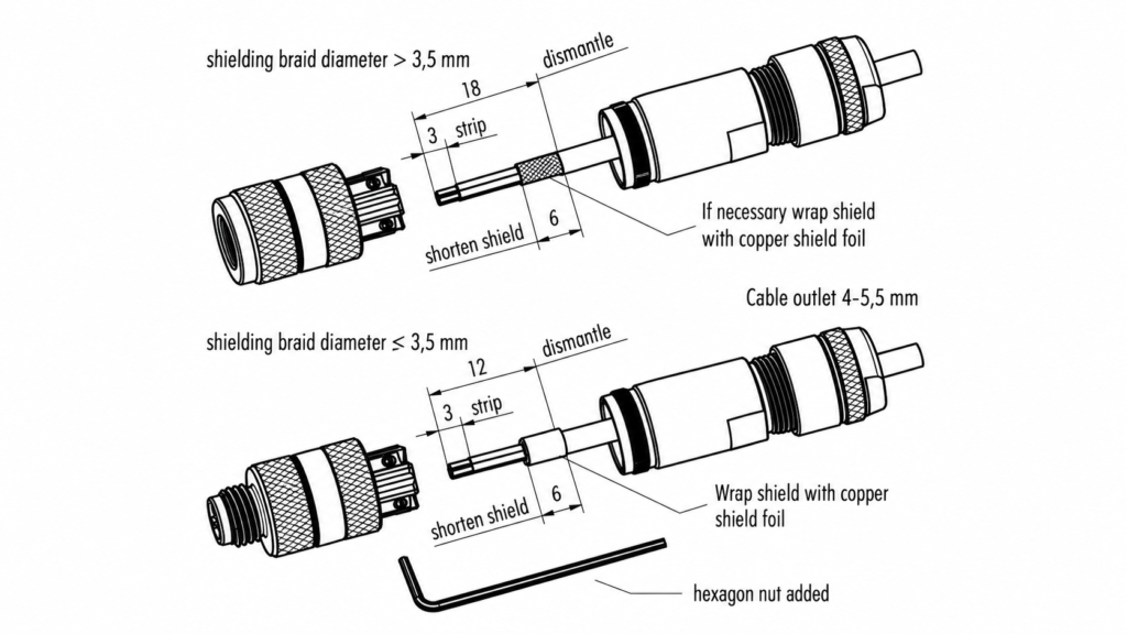
An accurate M8 cable quotation should define the connector interface before component sourcing begins. At minimum, confirm the number of contacts, connector gender, coding or keying, straight or right-angle orientation, pin assignment, mating interface and configuration of both ends. If an exact connector is mandatory, provide its manufacturer part number, equipment-side reference, drawing or an approved physical sample.
Confirm the Actual M8 Interface
“M8” identifies a compact industrial circular connector family, but it does not define the finished assembly. M8 interfaces commonly use an M8×1 threaded coupling, while commercially available connector families can still vary in contact arrangement, gender, coding, body construction, shielding method and cable entry. Three-, four-, five-, six- and eight-position products can be encountered depending on connector family and application, so contact count should always be stated rather than inferred from the product name.
For an existing sensor or machine, the equipment-side connection is often the most reliable reference. Providing the receptacle part number, existing cable number, equipment drawing or mating sample allows an engineering team to check compatibility before a component is ordered. This matters particularly when a project is being transferred from another supplier. Two M8 connectors may look almost identical in photographs while differing in keying, pin arrangement, dimensions or mechanical construction. In a second-source project, compatibility with the actual equipment is more important than finding a connector that simply looks similar to the original.
| Connector Item | Typical Project Choices | What to Confirm | Risk if Missing |
| Interface | M8 industrial circular connection | Exact mating interface | Mechanical incompatibility |
| Contact count | 3, 4, 5, 6 or 8 positions depending on family | Exact circuit requirement | Wrong connector selection |
| Gender | Male or female | End A and End B separately | Cannot mate with equipment |
| Orientation | Straight or right-angle | Cable exit direction | Installation interference |
| Coding / keying | Application-specific | Required mating configuration | Incorrect interface |
| Pinout | Straight-through or custom | Pin-to-wire assignment | Electrical malfunction |
| Shield termination | Shell, drain, one end, both ends or project-specific | Exact grounding method | EMC or grounding issue |
| End configuration | M8-to-M8, flying lead or other connector | Complete assembly definition | Incomplete BOM |
Define Gender and Orientation
Gender should be stated separately for each cable end because descriptions such as “M8 four-pin cable” do not identify whether the assembly uses a plug, socket or one of each. A sensor cable may be M8 female to flying leads, M8 male to M8 female, or M8 to another industrial connector. These assemblies can use different purchased components, assembly operations, fixtures and molded structures even when their overall lengths are identical.
Straight and right-angle connectors also need to be defined before quotation. A right-angle configuration is not simply a straight connector with the cable bent at ninety degrees. Its connector construction, insert orientation, cable exit and molding cavity can differ. In compact machinery, the cable may need to leave the connector upward, downward or to a particular side after mating. If this orientation is not shown, a sample may pass every electrical test and still interfere with an adjacent sensor, panel, enclosure wall or mounting bracket. A controlled drawing should therefore show the relationship between connector keying and cable exit whenever installation space is limited.
Lock the Pinout Before Sampling
Contact count and pinout are not the same thing. Two four-position M8 connectors may have identical external housings while carrying completely different circuits. A production drawing should identify each pin and its corresponding conductor color, wire number or opposite-end termination. For double-ended cables, the drawing should also make clear whether the connection is straight-through, crossed or arranged according to a customer-specific wiring scheme.
Shielding deserves the same level of detail. A note stating “shielded cable” explains the cable structure but not how the shield should be terminated. Depending on the application, it may connect to a connector shell, a drain wire, another specified point, one end only, both ends or remain isolated. These alternatives can change material preparation, soldering or crimping operations, inspection and electrical behavior. Once the wiring arrangement is approved, the pinout should become part of the production test program so continuity and wiring checks can verify the assembly against an objective reference instead of relying on appearance.
Use the Mating Device as the Reference
Replacement and second-source projects are usually easier when the manufacturer can evaluate the device-side connection rather than working from a general description. A mating connector part number, equipment interface drawing, dimensional information or approved original assembly can clarify mechanical fit, keying, contact arrangement and installation envelope before prototype components are selected.
A physical sample is valuable when documentation is incomplete, but the project should not depend indefinitely on one unlabeled sample sitting in a cabinet. After engineering review, the important information should be converted into controlled documentation covering connector type, pinout, orientation, cable dimensions, molding geometry and testing. That gives engineering, purchasing, production and quality teams one common reference. It also protects repeat orders years later, when the employees who originally developed the cable may no longer be involved and a visual comparison with an old sample is no longer a reliable manufacturing standard.
Which Cable Specifications Affect the Quote?
Cable construction can change material consumption, flexibility, electrical behavior, outside diameter, shielding, overmolding feasibility and processing time. A quote should therefore define finished length and measurement points, conductor count and size, shielding structure, cable jacket, outside diameter where important, color, identification and movement or environmental requirements instead of asking for an undefined “standard M8 cable.”

Define Length as a Measurable Dimension
“Two meters” sounds precise until two factories measure it from different reference points. One may measure connector face to connector face, another from the rear of each molded body, and a third may calculate the cut cable length before termination. Right-angle connectors make this ambiguity even more important because the reference point can change depending on the connector orientation and the shape of the molded body.
The drawing should therefore show exactly where length begins and ends. Tolerance should reflect the actual installation rather than simply using the tightest value a drawing system allows. A short cable fitted into a fixed enclosure may need relatively close dimensional control, while a longer cable routed freely through machinery can often accept more variation. Unnecessarily narrow tolerances may increase measurement, rejection and process-control effort without improving the way the finished cable performs in the equipment.
| Cable Parameter | Common Engineering Reference | RFQ Information Needed | Main Selection Value |
| Finished length | Sub-meter to 10 m+ is common in industrial assemblies | Exact length and measurement method | Installation fit and material usage |
| Length tolerance | Project-specific | Realistic drawing tolerance | Dimensional consistency |
| Conductor size | Roughly 0.14–0.50 mm² is often encountered in compact sensor cables | Required AWG/mm² or operating load | Electrical and physical design |
| Core count | Normally matched to circuit and connector contacts | Required number of conductors | Cable construction |
| Cable OD | Compact industrial constructions are often around 4–7 mm, depending on design | Maximum/minimum if critical | Mold entry and routing |
| Shielding | Unshielded, foil, braid or combined structure | Required structure and termination | EMC performance |
| Jacket | PVC, PUR, TPE or project-specific material | Material or application requirement | Environment and flexibility |
| Color | Standard or custom | Approved color reference | Identification |
| Printing | None or repeated identification | Artwork and printing requirement | Traceability |
| Motion | Static, occasional or repeated movement | Bend and flex conditions | Durability selection |
These values are useful reference ranges rather than universal M8 limits. Final conductor size, outside diameter, material, temperature rating and electrical performance should always follow the actual cable construction, connector limits and application conditions.
Match Conductor Size to the Real Load
Wire gauge should be chosen from the circuit requirement rather than from connector size alone. Voltage, current, signal function, cable length, acceptable voltage drop, temperature, flexibility and space inside the selected connector all influence conductor selection. Compact industrial sensor cables frequently use relatively small conductors, and constructions around 0.14 to 0.50 mm² are commonly encountered, but that range should not be copied automatically into every M8 project.
A low-current proximity sensor and a power-related connection can require different conductor sizes even though both use an M8 connector. During an early RFQ, voltage, current, signal type and cable length may be enough for an engineering review if the cable has not yet been selected. For a mature design, the preferred input is the exact approved cable part number or a controlled construction specification. Cable outside diameter must also be checked because moving from a smaller unshielded cable to a larger shielded construction can affect connector entry, sealing, strain relief and the dimensions of an existing overmold tool.
Specify Shielding as a Complete System
Shielding should be considered together with the electrical environment and termination method. A cable routed beside motors, drives, switching equipment or other electrical noise sources may require different construction from a basic sensor cable inside a protected control cabinet. Depending on the cable design, shielding may use foil, braid, drain wire or combinations of these structures.
The RFQ should define the required shield construction when an approved design already exists. If the product is still being developed, describe the equipment and EMC concerns so the structure can be reviewed. Termination is equally important. A shield connected to the connector shell at both ends behaves differently from a construction connected at one end or to a drain wire. A supplier that receives only the instruction “use shielded cable” may reasonably quote a construction that does not match the equipment grounding strategy. Clear shield termination details reduce that risk and make different supplier quotations easier to compare on the same technical basis.
Choose the Jacket from the Application
PVC, PUR and TPE are all used in industrial cable projects, but a material name should not be treated as a performance guarantee. Different formulations within the same polymer family can vary significantly in hardness, flexibility, abrasion resistance, temperature range, oil or chemical resistance and flame behavior. The correct material should therefore be selected from the application and confirmed against the actual cable specification.
PVC can be practical in many controlled, static or cost-sensitive installations. PUR is often discussed when abrasion resistance, industrial durability, oil exposure or flexible use is important. TPE and other compounds may be considered where different flexibility, environmental or temperature characteristics are needed. Instead of asking a manufacturer for “the strongest material,” explain whether the cable is installed indoors or outdoors, remains static or moves continuously, encounters oil or cleaning agents, experiences abrasion, or operates across a specified temperature range. That information allows engineering to evaluate a material against the job it actually needs to perform.
Control Color, Printing and Identification
Color and identification requirements may appear secondary compared with connector and conductor specifications, but they can affect material sourcing, minimum preparation quantities, sample approval and production setup. If a standard black jacket and molded body are acceptable, stating that early can simplify quotation. When a particular color is required, use an agreed color reference or approved sample rather than descriptions such as “industrial green” or “dark blue.”
Cable printing and labels should be specified with the same care. A drawing or artwork file should define customer part number, printing content, print interval, barcode, serial-number logic or other identification requirements. Label position can also matter when the cable is installed inside equipment or when a barcode must remain visible through packaging. For long-term supply programs, accurate identification supports receiving inspection, maintenance and revision control. It also reduces the risk of visually similar cable variants being mixed during production, packing or installation.
How Should the Overmold Be Defined?
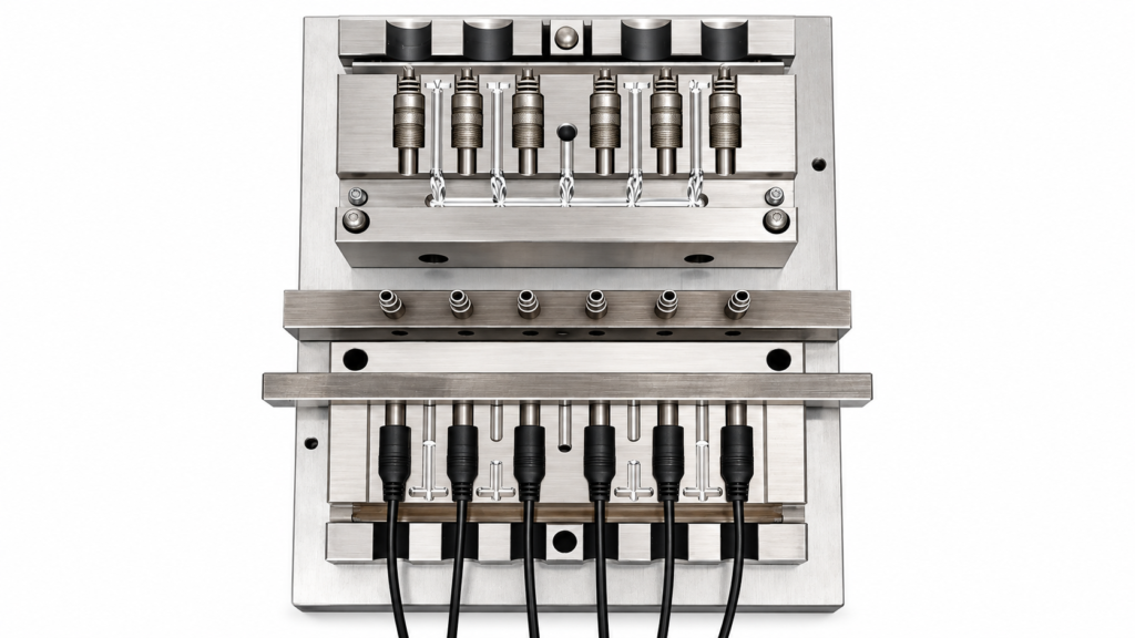
The overmold should be treated as an engineered component rather than decorative plastic around the connector. Geometry, dimensions, cable exit, strain-relief shape, material, hardness, color, sealing requirement, markings and tooling all require review. These decisions can influence connector protection, bending behavior, installation clearance, repeatability, testing and both one-time and recurring manufacturing costs.
Treat the Molded Body as an Engineered Part
An overmold forms the physical transition between a rigid connector and a flexible cable. Depending on design, it can protect the terminated area from handling, bending, pulling, dirt and moisture while creating a consistent external shape that can be reproduced in mass production. This is why an RFQ that says only “black overmold” leaves many important decisions unanswered.
A drawing should identify dimensions that affect installation, including overall molded-body length, maximum width or diameter, connector exposure, clearance around the coupling nut, strain-relief length and cable exit direction. Space is particularly important with compact M8 connectors because a body that is only a few millimeters wider than expected may interfere with nearby sensors, machine panels or adjacent connectors. Functional dimensions should receive the strongest tolerance control. Cosmetic contours that do not influence assembly or installation usually do not need the same level of dimensional restriction.
| Overmold Factor | Typical Options or Reference | RFQ Question | Main Effect |
| Geometry | Straight, right-angle, low-profile or custom | Can an existing shape be used? | Tooling |
| Material family | PVC, TPU, TPE or project-specific compound | Is material fixed or performance-based? | Flexibility and processing |
| Hardness | Flexible molding compounds may fall around Shore A 60–95 depending on grade | Is a specific hardness required? | Strain relief |
| Cable entry | Designed around actual cable OD | What OD must the mold accommodate? | Mold fit |
| Strain relief | Tapered, ribbed or extended flexible section | How will the cable move? | Bend concentration |
| Color | Standard black or custom | Is a controlled color needed? | Material preparation |
| Marking | None, logo or molded identification | Is custom tooling required? | Tool complexity |
| Sealing | General protection or defined IP target | What test must be passed? | Design and validation |
| Tooling | Existing, modified or new | Who owns and approves it? | One-time cost |
| Appearance | Texture, parting line, gate or surface criteria | What is acceptable? | Inspection standard |
Hardness values and material families should be treated as engineering discussion points, not guaranteed performance values. Final compound selection depends on cable jacket compatibility, required flexibility, molding process, environment and validation plan.
Design Strain Relief Around Real Movement
A good strain-relief design spreads bending over a controlled transition instead of allowing repeated stress to concentrate at the rear edge of the connector. The result depends on more than the number of ribs molded into the surface. Material hardness, cable flexibility, transition length, geometry, adhesion and the way the cable actually moves all influence mechanical behavior.
The RFQ should therefore describe whether the cable is static, moved occasionally during installation or service, or flexed repeatedly while machinery operates. When movement is important, provide available bend radius, motion direction, approximate cycle requirement and any simultaneous pulling or twisting. Cable manufacturers often express minimum bend radius as a multiple of cable outside diameter, and approximate values around 5–10 times OD are encountered in industrial constructions depending on whether the cable is static or moving. The selected cable datasheet should remain the final reference. When service life is critical, a defined flex or bending test is more useful than simply requesting a “heavy-duty strain relief.”
Define Waterproof Requirements with a Test
“Waterproof M8 cable” should be converted into a measurable project requirement before it becomes a production claim. M8 connector families are available for protected industrial environments, and IP67 or higher ratings are often discussed for suitable connector systems. However, a component rating should not automatically be applied to a complete custom cable assembly because the final result can depend on connector seals, cable diameter, jacket material, overmolding, assembly quality and the condition in which the product is tested.
If the finished cable must meet a specific ingress-protection target, include that target and the applicable test requirement in the RFQ. IP67, for example, represents defined protection conditions rather than a general synonym for “waterproof,” while IP68 requires test conditions appropriate to the declared product. When no formal rating is necessary, explain whether the cable faces rain, splashing, washdown, condensation, outdoor exposure or another moisture condition. That practical information allows the connector, overmold and sealing design to be evaluated without making an unsupported performance promise.
Separate Tooling Cost from Unit Cost
Custom overmolding can introduce development and tooling costs that behave differently from recurring unit cost. New tooling may be required when the project uses a particular connector insert, right-angle orientation, cable outside diameter, molded geometry, strain-relief profile, logo, surface texture or installation envelope. Existing tooling may sometimes be suitable for less restrictive projects, but compatibility should be verified before the production quotation is considered final.
A clear quotation should identify mold or fixture charges separately where practical. It should also clarify whether the tooling is customer-specific, how ownership is handled, whether future modifications are possible and what drawing revision controls tool approval. Once prototype geometry is accepted, the overmold dimensions, material, color, wiring, appearance limits and tests should be frozen in controlled project documentation. That makes the approved sample a physical confirmation of the specification instead of the only source of truth used to guide later production.
What Application and Test Requirements Matter?
The manufacturer needs to know where the cable will operate, what electrical or signal function it performs, what mechanical and environmental stresses it faces, and how acceptance will be verified. Equipment type, voltage, current, signal, movement, temperature, moisture, chemicals, abrasion, target market and test criteria can all influence connector selection, cable construction, molding, cost and production inspection.

Describe the Equipment, Not Just the Cable
“Industrial M8 cable” covers too many operating conditions to define one sensible construction. A description such as “M8 cable connecting a proximity sensor to an automated packaging machine” immediately gives engineering more useful context. The same connector family may also be used in monitoring equipment, control systems, robotics, factory machinery and outdoor sensing devices, and those applications do not necessarily need the same cable or molded structure.
A static cable inside a protected cabinet may prioritize compact routing and straightforward installation. A cable moving with automation equipment may require a different flexibility and bend-life review. Outdoor equipment can add moisture, temperature and UV considerations, while machinery may expose the cable to oil, abrasion, vibration or cleaning processes. Naming the application does not replace specifications, but it helps engineering recognize when the requested materials or construction may conflict with the way the cable is expected to operate.
| Application Condition | Information to Provide | Main Design Question | Possible Validation |
| Static indoor sensor | Length, circuit and routing | Is a standard industrial construction suitable? | Continuity, pinout, fit |
| Moving automation | Bend radius, motion and cycle expectations | Is flex-rated cable needed? | Bend/flex testing |
| Outdoor equipment | Moisture, UV and temperature | Are jacket and sealing suitable? | Environmental review |
| Oily machinery | Oil or chemical type and exposure | Is material compatible? | Material validation |
| Washdown environment | Water pressure, duration and chemicals | Is sealing design adequate? | Defined ingress test |
| Vibration | Equipment and mounting conditions | Is connector retention adequate? | Mechanical validation |
| Shielded signal | EMC environment and termination | Is shielding correctly designed? | Shield/continuity test |
| Power-related circuit | Voltage, current and conductor size | Are component ratings suitable? | Electrical testing |
| Export program | Market and documentation | What compliance evidence is needed? | Document review |
Define Electrical and Signal Requirements
Voltage, current and circuit function should be provided early because they influence conductor size, connector suitability, insulation and test requirements. Signal applications can also introduce shielding, grounding and wiring considerations. The manufacturer should work from actual operating values or the approved equipment specification rather than assuming that every cable using the same M8 connector can carry the same electrical load.
Continuity testing confirms whether the intended circuit has been connected, but it does not verify every electrical requirement. Depending on the product, additional checks may include insulation resistance, dielectric withstand, contact resistance, shield continuity or an equipment-level functional test. Acceptance values should come from the actual design, selected component ratings, customer specification or applicable standard. Applying one generic high-voltage or insulation criterion to every custom M8 cable is not good engineering practice. When wider equipment details are confidential, the project team can still provide the minimum electrical information necessary for cable selection and manufacturing validation.
Convert Mechanical Risks into Test Criteria
Requests such as “strong cable,” “good strain relief” or “high durability” are difficult to control during production because they do not contain measurable acceptance criteria. When pull resistance matters, the drawing or quality plan should define the load, direction, duration, fixture and pass condition. Repeated bending should similarly define bend angle, radius, cycle count, applied load and whether electrical continuity is monitored during the test.
A practical M8 cable test plan may combine continuity and pinout checks with connector-fit inspection, pull-force testing, repeated bending, insulation testing, dielectric withstand, dimensional inspection, molded appearance review or defined sealing validation. The correct combination depends on how the cable will be used. Adding every available laboratory test does not automatically make a product more reliable; it can simply increase cost and inspection time. The goal is to identify the failure modes that would matter in the actual equipment and create test methods that can detect them before shipment.
Confirm Compliance Before Materials Are Frozen
Target-market and customer documentation requirements can affect material selection, sourcing, testing, cost and development timing, so they should be discussed before samples are approved whenever possible. A project may require restricted-substance declarations, customer-approved materials, flame-related documentation, environmental reports or third-party testing. These needs should be defined for the actual part number rather than expressed as a general request for “all certifications.”
A connector, raw cable and molding material may each have their own documentation, while the complete assembly can have a different compliance scope. For that reason, certifications such as UL-related approvals, CE-related responsibilities, RoHS documentation or REACH information should be reviewed according to the product, target market and customer specification instead of being assumed across every custom cable. A more useful procurement question is which documents and tests the exact finished assembly requires and what evidence must accompany production. Addressing that question before material approval reduces the chance of discovering a documentation gap after samples or bulk materials have already been prepared.
How Do RFQ Files and Quantities Affect the Quote?
A production-ready quotation needs both technical specifications and commercial information. The RFQ package should include the latest drawing, wiring information, connector and cable references, available samples, testing requirements, quantity levels, tooling expectations, packaging, labeling and a clear list of unresolved items. The more controlled these inputs are, the fewer hidden assumptions remain in material, tooling, testing and production calculations.
Build One Controlled RFQ Package
A strong RFQ gives engineering, purchasing, quality and production teams one consistent version of the product. The 2D drawing normally acts as the central document because it can combine connector ends, orientation, finished length, measurement references, pinout, cable specification, molded dimensions, labels and tolerances in one controlled source. Supporting information can include BOMs, connector datasheets, cable specifications, wiring tables, application photographs, equipment-interface drawings, testing requirements and packaging artwork.
Projects can still begin when this package is incomplete. A hand sketch, physical sample, connector model, approximate cable length and application description may be sufficient for an initial review. The difference is that the resulting quotation should be understood as preliminary while unresolved items remain visible. The following simple readiness check is not an industry certification, but it is useful for identifying how much supplier interpretation still exists before production pricing can be compared reliably.
| RFQ Element | 0 Points | 1 Point | 2 Points |
| Connector | “M8 connector” only | Gender/pin count partly known | Exact interface or approved PN |
| Pinout | Missing | Functional description | Controlled wiring table |
| Cable | “Standard cable” | Length/material partly known | Approved construction |
| Overmold | “Overmolded” only | General shape | Controlled dimensions/material |
| Application | Unknown | General industry | Actual equipment/environment |
| Testing | Missing | General test request | Defined tests and criteria |
| Quantity | Missing | One estimated quantity | Prototype and production tiers |
| Packaging | Missing | Basic packing | Approved packing and labels |
| Total | 0–5: budgetary basis | 6–11: preliminary RFQ | 12–16: strong production-quote basis |
Control Drawing Revisions
Revision control becomes critical as soon as a cable changes during development. A project might begin with a straight M8 connector, change to a right-angle version after installation testing and later change cable length or strain-relief geometry. If purchasing sends the newest drawing while the supplier’s engineering team still works from an earlier revision, both sides may believe they are discussing the same part even though important construction details differ.
The drawing should include the customer part number, drawing number, revision, units, date and approval status. A revised quotation should identify the changes that may affect material, tooling, processing, testing or packaging. The same revision reference should flow through sample approval, inspection records, packaging artwork, purchase orders and production documentation where practical. This creates a traceable link between what was quoted, what was approved and what is ultimately manufactured. It is especially valuable in long-term supply programs where the project may continue long after the original development team has moved on.
Quote Realistic Quantity Tiers
Order quantity changes more than the final multiplication of unit price. Connector suppliers, cable mills, custom colors, labels and packaging materials can have their own minimum quantities or price breaks. Production also involves setup work such as mold installation, first-piece confirmation, fixture preparation and test-program configuration that behaves differently at 500 pieces and at 20,000 pieces.
A useful RFQ can show prototype demand, first production quantity and realistic repeat-order levels. Quantity breaks such as 500, 2,000, 5,000 and 10,000 pieces can be useful when they reflect a plausible purchasing plan rather than an inflated forecast intended only to obtain the lowest theoretical price. Tooling, fixtures, specialized test adapters and other one-time charges should be separated when possible so procurement can understand the economics of the first order and later repeat production. For many custom cable projects, MOQ discussion may begin around 500 pieces, but the final requirement depends on connector sourcing, cable construction, material, overmolding, tooling and packaging.
Define Packaging Before the Final Quote
Packaging can materially influence labor, packaging materials, carton utilization and export preparation, particularly when assemblies are long, molded connectors require protection or the product must enter a customer’s receiving system with specific identification. A basic industrial project may use coiled cables in protective bags and master cartons, while another may require connector caps, serialized barcode labels, trays, defined coil diameters, inner cartons or customer-specific carton markings.
Packing methods should respect cable construction. A long cable should not be forced into a coil tighter than its permitted bend radius simply to save carton space. When the cable specification provides a minimum bend requirement, packaging should take it into account. Label content, position and barcode format should also be approved before final production when they form part of the delivered product. Reviewing these details during sampling prevents a situation in which the cable itself is approved but packaging changes the quotation shortly before shipment.
Keep Preliminary Assumptions Visible
A useful quotation can be created before every engineering detail is frozen, provided its assumptions are visible. An early quote might state that pricing is based on a four-position M8 interface, approximately two meters of black industrial cable, a standard black molded body, customer-provided pinout, no custom logo and a defined estimated order quantity. That statement allows procurement to understand the commercial basis instead of treating a low-detail number as a permanent production commitment.
As development progresses, those assumptions can be replaced by confirmed connector part numbers, cable construction, molding geometry, testing, packaging and drawing revisions. Price changes then become easier to explain because the technical cause is visible. A project that changes from unshielded PVC to shielded PUR, adds a right-angle custom mold and introduces a defined ingress test has not simply “become more expensive”; it has become a different manufacturing specification. Transparent RFQ assumptions make that distinction clear and allow different suppliers to be compared on a genuinely equivalent basis.
Request a Custom Overmolded M8 Cable Quote
A complete RFQ does not have to start as a perfect engineering package. If your project is still being developed, begin with the information already available: connector reference, mating interface, pinout, target cable length, application, photographs, sample, expected quantity and any known environmental or testing requirements. Engineering review can then identify which open points need to be confirmed before tooling, prototype production or bulk material purchasing begins.
Cablivo supports custom cable, wire harness, cable assembly and molded or overmolded cable projects from requirement review and drawing evaluation through sample development, production preparation, testing, labeling, packaging and shipment coordination. For an overmolded M8 cable project, the useful starting point is not a generic request for “the best price,” but a clear description of the connection that needs to work in the actual equipment. Send the drawing, existing sample, connector information or RFQ package you currently have, and the remaining connector, cable, molding, testing and production details can be reviewed around the real requirements of the project.



