 Skip to content


Two molded cable assemblies can look almost identical on a desk and still require very different connectors, cable constructions, molding materials, tooling, production processes, tests, and total project costs. A photo may show cable color and the approximate connector shape, but it rarely reveals the conductor structure, pinout, molded material, internal termination, dimensional tolerance, strain-relief requirement, environmental exposure, or inspection criteria. That is why a quotation based on a message such as “one-meter black molded cable, 1,000 pieces” is normally built on assumptions rather than a controlled manufacturing specification.
To quote a molded cable assembly accurately, provide the drawing or sample, connector part numbers, pinout, cable construction and finished length, molded dimensions, overmold material, cable exit direction, tooling status, application environment, testing requirements, expected quantities, packaging, and labeling requirements. When some details are still unknown, mark them clearly so the manufacturer can review the open specifications before final pricing. A good RFQ does not need to be complicated, but it should make it possible for engineering, sourcing, production, and quality teams to understand the same product.
Many quotation problems begin with something that appears small. The original request may look straightforward until an engineer discovers that the cable needs a controlled 90-degree exit, a softer molded transition, a different connector source, a sealing structure, a specific pull-force test, or custom packaging with variable labels. Any one of those requirements can affect tooling, materials, sampling, testing, or production time. The practical question is therefore not simply, “How much does this cable cost?” It is, “Have we defined the same cable that we expect the factory to manufacture repeatedly?”
What Should Be Included in the RFQ?
A useful molded cable assembly RFQ should identify the product, application, available drawings or samples, expected quantities, and any known requirements that could change materials, tooling, processing, testing, packaging, or delivery. Every specification does not have to be final before contacting a manufacturer, but confirmed requirements and unresolved engineering questions should be separated clearly so assumptions do not quietly become part of the quotation.
What Project Documents Are Available?
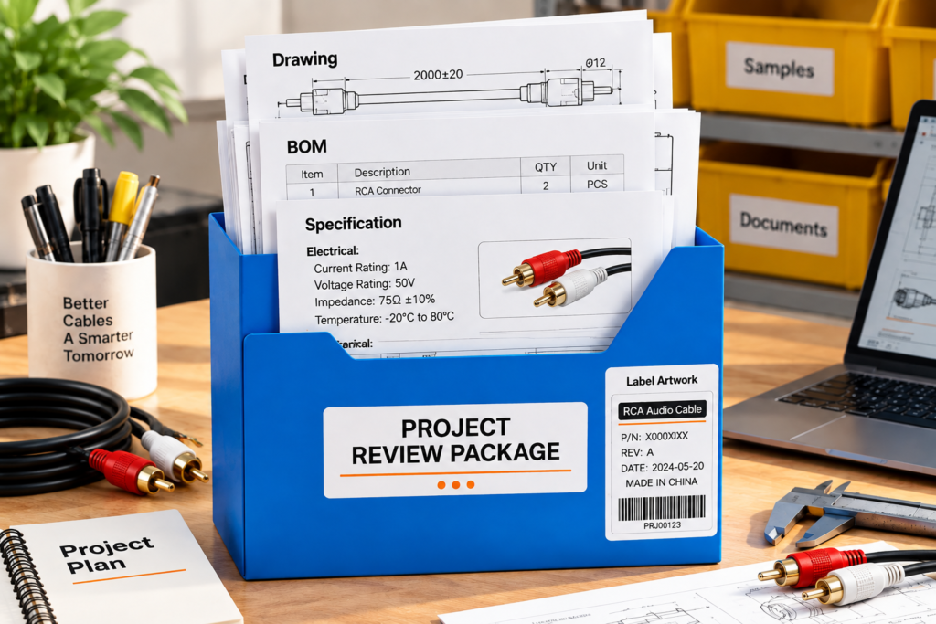
A controlled 2D drawing is usually the most useful starting point because it can place connector orientation, cable length, molded dimensions, tolerances, pinout references, and drawing revision in one controlled document. A stronger RFQ package may also contain a BOM, connector datasheets, wiring diagram, material specifications, 3D files where geometry is complex, sample photographs, test requirements, and an existing physical product. These documents have different roles, so a photograph should not be treated as a substitute for information that can only be confirmed through a drawing, BOM, or electrical specification.
Not every project begins with a complete engineering package. A mature product being transferred from another supplier may arrive with an old drawing and a physical sample, while a new development project may begin with connector information, several photographs, a sketch, a target cable length, and an explanation of how the assembly will be installed. Both situations can be reviewed, but the quotation should clearly distinguish verified requirements from items that still require engineering confirmation. Cablivo’s documented engineering scope includes drawing review, sample review, BOM review, connector confirmation, pinout review, overmold structure review, tooling discussion, prototype development, and sample revision.
A physical sample is especially valuable when molded appearance, cable flexibility, connector fit, grip feel, or routing behavior matters. However, a finished sample normally cannot prove the precise conductor stranding, resin grade, internal termination process, electrical limits, or original inspection standard. When those details are important to performance or cost, they should be documented separately rather than reverse-engineered by assumption. The RFQ should also show whether a drawing is an approved production revision, a reference drawing, or an early concept, because those statuses carry very different levels of manufacturing authority.
What Is the Cable Used For?
Application information gives meaning to the technical specification. A molded cable permanently installed inside a control cabinet experiences different stresses from a handheld assembly that is repeatedly bent close to the connector. An outdoor product may be exposed to water, dirt, temperature variation, vibration, sunlight, oils, or cleaning chemicals, while a cable installed inside compact electronics may be more sensitive to cable diameter, connector orientation, bend radius, and installation clearance. The same connector and nominal cable length can therefore require very different materials and molded structures.
The RFQ should explain what the assembly connects, where it will be installed, whether it moves during operation, how often it is plugged and unplugged, and which environmental conditions are relevant. Installation restrictions should also be stated early. If the cable needs to pass through a small opening, leave a connector at a 90-degree angle, move with a machine axis, remain flexible in a low-temperature environment, or fit behind a narrow panel, those conditions can directly influence the cable construction, molded geometry, and strain-relief design.
Application context also prevents materials from being selected by habit. A request for “TPU molding” is less useful than an explanation that the molded end must tolerate abrasion, oil contact, frequent flexing, or outdoor exposure. Once the actual performance target is understood, an engineer can assess whether TPU, TPE, PVC, or another suitable compound is appropriate. In practical custom manufacturing, the purpose of the cable should guide material and structural decisions rather than the material name being selected first and the application considered afterward.
What Quantity Should Be Quoted?
Quantity is not only a purchasing field because it can influence tooling strategy, component sourcing, material preparation, production setup, inspection planning, and packaging. Prototype samples, pilot production, a first purchase order, and recurring annual demand have different economic structures. A manufacturer that knows only the long-term forecast may not understand the immediate development requirement, while a manufacturer that sees only the first small order may recommend a production approach that is not suitable for the expected program volume.
A stronger RFQ therefore separates development volume from commercial volume. For example, the project may require a small engineering sample run, followed by an initial production quantity and later recurring orders. Procurement can also request price breaks at realistic levels such as 500, 2,000, and 10,000 pieces when those quantities reflect genuine purchasing scenarios. The purpose is not to create as many pricing tiers as possible; it is to reveal whether tooling, materials, or production efficiency change meaningfully as the project scales.
Cablivo’s documented MOQ starts from 500 pieces for many custom cable projects, while the final MOQ depends on connector type, cable structure, material, overmolding requirements, tooling, packaging, and order quantity. For a molded cable project, a realistic quantity forecast helps the engineering and commercial teams discuss whether the same tooling and production arrangement can reasonably support both the first order and the expected long-term program.
What Information Is Still Open?
An incomplete specification is not automatically a weak RFQ. A hidden assumption is usually more dangerous. If the final overmold hardness, connector source, packaging format, test level, color match, or environmental requirement has not been decided, it is better to mark that item as pending confirmation than to allow a supplier to quietly select an option and build the price around it. The quotation can then identify which values are fixed and which may require revision after engineering review.
A practical project file can classify specifications as confirmed, preferred, reference only, or to be determined. “Connector manufacturer and part number confirmed” should normally be treated differently from “black TPU preferred.” The first is a controlled component choice. The second may still allow discussion about hardness, grade, material compatibility, appearance, or cost. The same distinction helps when comparing quotations from several manufacturers because it reduces the risk that different suppliers price different technical assumptions under the same product description.
This approach also makes revisions easier to manage. If the waterproof target, cable OD, molded geometry, or test coverage changes later, the commercial team can identify exactly which quotation inputs changed rather than reopening the entire project. For complex molded assemblies, accurate revision control can be as valuable as the initial RFQ because engineering changes often continue through the sample stage before the final production specification is approved.
| RFQ Item | Useful Information | Decision Status | Main Quote Impact |
| Drawing | Dimensions, tolerances, revision | Confirmed / reference | Manufacturing definition |
| Sample | Physical sample or clear photos | Reference / approved master | Appearance and fit |
| BOM | Cable, connector, terminals, resin | Confirmed / partial | Material and sourcing |
| Application | Equipment, movement, environment | Confirmed | Material and structure |
| Quantity | Samples, first order, forecast | Estimated / confirmed | Tooling and unit economics |
| Open items | Material, test, color, packaging | TBD | Possible quotation revision |
| Required date | Sample and production target | Target | Scheduling and sourcing |
A useful RFQ does not need to contain unnecessary paperwork. It needs to make the engineering definition visible enough that the manufacturer can identify what is known, what must be manufactured, what still requires discussion, and which unresolved points could materially change the final quotation.
Which Cable and Connector Specifications Matter?
The quotation should define the cable construction, finished dimensions, connector part numbers, contact arrangement, orientation, pinout, and electrical requirements that affect material selection or production. In molded assemblies, cable OD and connector geometry deserve particular attention because both interact directly with the mold. A small change in cable diameter, connector source, or rotational orientation can create a tooling or assembly issue that is much larger than the dimensional change itself.

Which Cable Construction Is Required?
“Four-core black cable” is not a manufacturing specification. An RFQ should identify conductor count, AWG or conductor cross-sectional area, conductor material, stranding, insulation, shielding when required, outer jacket material, nominal cable OD, color, and any relevant flexibility or environmental performance. These items influence not only raw material cost but also stripping, termination, crimping or soldering, cable handling, molded transition design, and final inspection.
Conductor size matters because it influences current capability, resistance, cable diameter, terminal compatibility, and termination process. Stranding can also become important in applications involving frequent movement. Two conductors with similar cross-sectional area can behave differently when one uses relatively large strands and the other uses many finer strands. Where flexibility is important, conductor construction should therefore be discussed together with the finished cable structure rather than treating AWG as the only meaningful parameter.
For signal and communication assemblies, shielding should be described more precisely than simply “shielded.” The project may require foil, braid, foil plus braid, a drain wire, or a specific shell termination method. Shield termination can affect preparation time and electrical performance, so it belongs in the assembly definition. Cable OD is especially important in molded projects because the cable physically enters the molding cavity. A change from roughly 5.0 mm to 5.8 mm may appear small in a purchasing spreadsheet but can be significant at the overmold interface, strain-relief transition, or sealing area.
What Cable Length and Tolerance Are Required?
Finished length should have a clear measurement method. “One meter” can mean different things if one engineer measures connector tip to connector tip while another measures between molded reference surfaces. Assemblies with branches, exposed leads, right-angle connectors, or different connector lengths create even more room for interpretation. A controlled drawing should therefore show the measurement reference points rather than leaving the definition inside an email conversation.
Depending on the product, useful dimensions may include overall finished length, branch lengths, exposed conductor lengths, strip dimensions, heat-shrink positions, breakout points, label locations, molded body dimensions, and cable exit direction. Each critical dimension should also have an appropriate tolerance. Tight tolerances should be reserved for dimensions that affect fit or function because unnecessarily restrictive tolerances can increase inspection effort without improving the final application.
A cable installed loosely inside a large enclosure may tolerate more overall-length variation than one connecting two fixed interfaces inside a compact assembly. The correct tolerance therefore depends on how the product is used. When a project is copied from an existing sample, the sample can provide reference measurements, but production-critical dimensions should eventually be transferred into a controlled drawing. That prevents later orders from being judged against informal measurements taken from different physical samples.
Which Connectors and Pinouts Are Required?
Connector identification should be as specific as possible. Manufacturer, series, exact part number, gender, number of contacts, mating interface, keying, locking method, terminal type, and relevant accessories can all influence sourcing and production. Terms such as “M12 connector,” “USB connector,” “waterproof 4-pin connector,” or “DC plug” can describe many mechanically or electrically different products, so they are usually not sufficient on their own for a controlled quotation.
Pinout information should show the complete electrical relationship from one end of the assembly to the other. That can include pin numbers, conductor colors, terminal positions, polarity, shielding, grounding, drain wires, jumpers, and unused contacts. For a multi-branch assembly, each conductor route should be unambiguous. This becomes even more important when wire colors are repeated or when a connector housing supports several optional contact configurations.
Orientation is particularly important for right-angle molded connectors. Once the connector and cable are held by the overmold, rotational orientation and cable exit direction become fixed mechanical features. A product can pass continuity testing and still be unusable because the cable exits toward the wrong side of the equipment. For that reason, rotational clocking should be shown from a defined viewing direction or datum rather than relying on a photograph whose orientation may be interpreted differently by different people.
Do Electrical Requirements Need to Be Defined?
Electrical requirements should be provided whenever they can change the conductor, insulation, connector, terminal, shielding, or test process. Depending on the project, relevant parameters may include operating voltage, current, conductor resistance, insulation resistance, dielectric withstand requirement, signal type, impedance, grounding arrangement, or shielding expectation. Not every molded assembly needs every parameter, but the electrical definition should be detailed enough to explain which cable construction is acceptable.
The level of specification depends on the product. A simple low-voltage switch lead may need far less information than a high-current power assembly, high-speed data cable, RF connection, or sensitive signal cable. A practical test is to ask whether changing a given electrical requirement could force the manufacturer to select a different conductor, cable construction, connector, termination method, or test procedure. If the answer is yes, that requirement belongs in the RFQ.
Where a controlled electrical specification already exists, sending the original document is safer than summarizing it informally. Acceptance criteria are especially important. “Resistance test required” does not define the measurement points, maximum resistance, temperature condition, or whether the requirement applies to individual conductors or the entire circuit. Clear numerical or referenced criteria allow the engineering and quality teams to plan a comparable test rather than making their own interpretations.
| Specification | Typical RFQ Detail | Manufacturing Relevance | Risk if Missing |
| Conductor | AWG / mm², count, stranding | Material and termination | Wrong current or flexibility |
| Shielding | Foil, braid, drain, termination | EMI structure and assembly | Signal inconsistency |
| Jacket | Material, OD, color | Mold fit and environment | Tooling mismatch |
| Length | Datum points and tolerance | Cutting and inspection | Installation problem |
| Connector | Exact part number | Sourcing and mold interface | Wrong mating component |
| Pinout | Pin-to-pin mapping | Assembly and testing | Wrong wiring |
| Orientation | Clocking and cable exit | Molded geometry | Installation failure |
| Electrical limits | Voltage, current, resistance, impedance | Material and test selection | Under-specified performance |
Cable and connector specifications should be considered as one system because the molded body is designed around both. If the connector housing, cable OD, pinout, shielding termination, or cable exit changes, the consequences can extend beyond the component itself and affect tooling, assembly fixtures, testing, appearance, or sample validation.
What Molded and Tooling Details Affect the Quote?
The molded portion should be treated as an engineered component rather than a decorative cover. Geometry, cable exit direction, resin, hardness, color, surface finish, strain relief, sealing, and tooling status can all change the quotation. These details affect mold design, processing conditions, sample development, dimensional control, appearance standards, material consumption, and whether the same molded structure can be reproduced reliably during future production runs.

What Molded Shape Is Required?
Overmold geometry affects function, appearance, installation, and manufacturing. A useful drawing should define the molded envelope, length, width, height, connector exposure, cable exit position, grip area, transition profile, strain-relief geometry, and any surfaces that must remain clear for mating, fastening, or installation. A molded body that appears simple in a product photograph may contain several geometry decisions that determine whether the connector can be inserted correctly and whether the cable can route through the customer’s equipment.
Small dimensional changes can have practical consequences. If the molded body extends too far toward the mating face, it can interfere with a locking tab or panel opening. If the transition is too thick, it may improve stiffness while reducing useful flexibility. A grip feature may make the connector easier to handle but increase the overall envelope beyond the available clearance. These features should therefore be evaluated against both the mating component and the installation environment instead of being approved only for appearance.
Straight, angled, and low-profile cable exits also require different mold arrangements. When rotational orientation matters, it should be specified from a clear datum. For replacement projects, an existing approved sample can help establish molded shape, surface appearance, and connector exposure, but the final production drawing should still identify which dimensions are critical. Cablivo’s documented molded-cable capabilities include connector overmolding, strain-relief structures, customized molded appearance, tooling development, sample validation, and support for repeatable production.
Which Overmold Material Is Required?
Common molded cable projects may use PVC, TPE, TPU, or other thermoplastic compounds, but the correct material depends on the application and on how the molded material interacts with the underlying connector and cable jacket. Flexibility, hardness, abrasion resistance, chemical exposure, temperature range, appearance, processing behavior, adhesion, and documentation requirements can all influence material selection. The cheapest or softest material is not automatically the most suitable.
If the project already controls a specific resin manufacturer and grade, that information should be shown in the BOM. When the exact grade has not been selected, the RFQ should describe the required performance. For example, “repeated flexing with occasional oil contact” gives an engineer much more useful context than simply requesting “TPU.” The material can then be reviewed against the cable jacket, molded wall thickness, desired flexibility, operating environment, and expected production process.
Hardness is another commonly overlooked parameter. A softer compound can create a more flexible molded transition, while a harder material can produce a different grip feel and structural response. The correct hardness cannot be chosen independently from geometry. Color should also be defined according to the commercial requirement. A standard black overmold is different from a customer-controlled color that requires matching against a reference, sample approval, or tighter cosmetic inspection. Each additional controlled appearance requirement can affect material preparation and the sample approval process.
Is Strain Relief or Sealing Required?
Strain relief manages the transition between a flexible cable and a comparatively rigid connector area. Its length, wall thickness, molded profile, compound hardness, and cable exit angle influence where the assembly bends when pulled or flexed. The correct design therefore depends on real movement. A permanently installed cable may only need basic protection at the termination, while a handheld product or moving equipment cable may require much more attention to repeated bending near the molded transition.
A larger or softer strain relief is not automatically better. An excessively long transition can interfere with installation space, and a design that is too stiff may simply move the bending point farther down the cable. The practical goal is to distribute mechanical stress in a way that suits the actual application and the flexibility of the cable rather than selecting a generic molded profile.
Sealing requires the same level of discipline. Overmolding can support connector protection and sealing, but an overmolded product should not automatically be treated as waterproof to a defined rating. Performance depends on the connector interface, mating seal, cable jacket, molded material, geometry, and validation method. If the project requires protection from water or dust, the RFQ should define the intended environment and test requirement. Cablivo’s documented manufacturing capability specifically links overmolding with connector protection, strain relief, sealing structures, and repeatable molded appearance after sample approval.
Is New Tooling Required?
Tooling can create one of the largest commercial differences between otherwise similar molded cable projects. A customer may provide an existing mold, transfer a tool from another supplier, request modification to an old mold, begin with prototype tooling, or require a completely new production tool. The quotation should make clear which situation applies because the tooling route affects development cost, sample timing, production planning, and sometimes unit economics.
An existing mold should be inspected before anyone assumes that it can be installed and used immediately. Important considerations include physical dimensions, machine compatibility, runner and gate design, cavity condition, cable and connector positioning, tool material, ownership, maintenance history, and compatibility with the intended molding compound. Even when the original part drawing is available, the condition and construction of the physical tool may still determine whether transfer is practical.
For a new mold, expected production volume, cosmetic requirements, cavity strategy, molded geometry, material, and the likelihood of later design revision all influence how the tool should be approached. Sample approval provides the bridge between tooling and volume production. If geometry or appearance changes during sampling, the controlled drawing and mold status should be updated before production release. Cablivo’s documented mold engineering support includes tooling review, overmold structure evaluation, tooling feasibility, mold adjustment, and sample-stage modification for molded and overmolded cable projects.
| Molded Requirement | Information to Confirm | Decision Value | Possible Quote Effect |
| Molded geometry | Length, width, height, exposure | Equipment fit | Tool complexity |
| Cable exit | Straight, angled, clocking | Installation clearance | Cavity and fixture design |
| Material | Resin grade or performance | Environment suitability | Material and processing |
| Hardness | Required range if critical | Flexibility and support | Resin selection |
| Color | Standard or controlled reference | Cosmetic requirement | Sampling and preparation |
| Strain relief | Shape and movement condition | Mechanical protection | Geometry and validation |
| Sealing | Environment and test method | Protection requirement | Tool and test complexity |
| Tooling | Existing, modified, new | Production strategy | One-time tooling cost |
| Approval | Drawing and approved sample | Production release | Revision control |
Treating the molded section as an engineering component helps prevent a common purchasing problem: two quotations that use the same connector and cable but assume completely different molding structures. Once molded geometry, material, tooling, and validation criteria are aligned, unit-price comparisons become much more meaningful.
Which Testing and Application Requirements Matter?
Testing should follow the actual risks of the application rather than using one universal checklist for every molded cable. Continuity, insulation, pull force, repeated bending, connector life, dimensions, environmental exposure, sealing, and appearance may all be relevant. The RFQ should identify the required test, acceptance criteria, testing frequency, and documentation expectations whenever those conditions can influence manufacturing cost or product release.

Which Electrical Tests Are Required?
Continuity testing is common because it can identify open circuits, shorts, and incorrect wiring, but it should not automatically be treated as complete electrical validation. Depending on the application, a project may also require conductor resistance, insulation resistance, dielectric withstand or Hi-Pot testing, polarity verification, impedance-related checks, shielding verification, or application-specific functional testing. Test selection should follow the cable’s electrical role rather than simply adding every available test.
The acceptance criterion matters as much as the test name. “Hi-Pot required” does not define the test voltage, duration, leakage limit, test points, or whether the procedure applies to every production piece. “Resistance test” similarly does not explain the measurement circuit or maximum value. A controlled customer specification or test method is therefore more useful than an informal description when electrical requirements are important.
Testing frequency can also change the quotation. A development test conducted on several validation samples has a different labor and documentation requirement from a test that must be performed on 100% of production. Serialized data, lot-level reports, or test records supplied with each shipment add another layer of quality documentation. Cablivo’s documented capabilities include cable functional testing, continuity-related checks, Hi-Pot and insulation testing, pull-force testing, and visual inspection for applicable projects.
Which Mechanical Tests Are Required?
Mechanical validation is particularly relevant around molded terminations because cable flexibility, internal termination, connector rigidity, and strain relief meet at the same location. Pull-force testing can help evaluate whether the assembly maintains its mechanical integrity under an agreed axial load. Repeated bending or swing testing may be relevant for moving cables, while insertion and withdrawal testing can be useful when the connector is expected to be connected and disconnected repeatedly during service.
A useful test reproduces a meaningful failure mode. A bending test should define the angle, radius, load, frequency, and cycle requirement when those variables are controlled by the project. A pull test should define force direction, fixture method, duration, and acceptance criterion. Without these conditions, two factories can both report a “pull test” while applying different methods that produce results which cannot reasonably be compared.
The required test level should also match actual use. A connector that remains installed throughout the equipment life may not need the same mating-cycle target as a service connection unplugged every day. Cablivo’s documented molded and overmolded cable resources include pull-force and connector insertion-life testing equipment that can support project-specific validation when those tests are required.
Which Environmental Conditions Must Be Defined?
Terms such as “industrial grade,” “outdoor,” or “heavy duty” are too broad to define a material or test requirement on their own. The RFQ should describe the actual environment: water, humidity, heat, low temperature, oils, cleaning chemicals, salt, sunlight, vibration, abrasion, dust, or repeated movement. These conditions can influence the cable jacket, molded compound, connector choice, sealing structure, and validation plan.
Specific information is more useful than general performance language. If temperature matters, provide the expected operating or storage range where known. If chemicals are important, identify the substance or cleaning process rather than asking generally for “chemical resistance.” If the cable moves, describe the movement and location of bending. These details help the engineering team select a structure that matches the application rather than over-engineering the product against every theoretical risk.
The complete connection also matters. A molded body may protect the cable-to-connector transition but cannot compensate for an unsuitable mating interface. A connector can be sealed when fully mated yet behave differently while disconnected. Environmental requirements should therefore be considered at system level. The molded cable is only one part of the connection, and the RFQ should make clear which performance is expected from the complete assembly.
Are Compliance and Acceptance Requirements Needed?
Compliance requirements should be connected to the real product, target market, application, and customer specification. Depending on the program, the RFQ may need to identify material declarations, customer restricted-substance requirements, component certifications, inspection documentation, traceability, test reports, or other market-specific requirements. These conditions can influence material sourcing and quality documentation, so they should be disclosed before materials are approved rather than after samples have already been produced.
Cosmetic acceptance also deserves clear criteria when the molded connector is visible to the end user. Injection-molded parts can naturally show parting lines, gate areas, minor texture variation, or other process characteristics. If the project requires tighter control of flash, sink marks, scratches, color variation, surface texture, logo position, or connector alignment, the acceptance standard should be established during sample development. An approved visual sample can be useful when combined with controlled drawings and specifications.
Cablivo’s factual documentation states that certification and testing requirements should be confirmed according to product type, target market, and project specifications rather than assuming that every cable automatically carries the same certifications or test claims. This project-specific approach helps keep quotations realistic while ensuring that required compliance documentation is considered before production planning begins.
| Test Area | Typical Requirement | What Must Be Defined | Quality Decision |
| Continuity | Open/short and wiring check | Circuit and coverage | Correct wiring |
| Hi-Pot / insulation | Electrical isolation | Voltage, duration, leakage | Insulation integrity |
| Resistance | Circuit resistance | Limit and test points | Electrical performance |
| Pull force | Mechanical retention | Force, direction, duration | Connection strength |
| Flex / swing | Repeated movement | Angle, load, radius, cycles | Durability |
| Insertion life | Repeated mating | Cycle count and criteria | Connector durability |
| Environmental | Temperature, humidity, water, corrosion | Exposure and method | Application suitability |
| Dimensions | Critical drawing features | Tolerance and sampling | Assembly fit |
| Appearance | Flash, sink, color, alignment | Approved standard | Cosmetic acceptance |
A good test plan is not the one with the greatest number of test items. It is the one that addresses the actual electrical, mechanical, environmental, and cosmetic risks of the project and defines acceptance clearly enough that samples and production can be judged against the same standard.
How Do Quantity and Production Details Affect Pricing?
Molded cable pricing depends on more than the cable and connector. Production volume, tooling, sample development, component availability, test coverage, packaging, labeling, and documentation can all influence the commercial structure. Providing realistic quantities and production requirements helps separate one-time development costs from recurring unit costs and gives the factory a stronger basis for sourcing, setup, quality planning, packaging, and delivery scheduling.

How Does Order Volume Affect the Quote?
A prototype and a recurring production program may use the same drawing while having very different cost structures. During development, engineering review, tool preparation, setup, material preparation, and sample validation are spread across relatively few parts. As production volume increases, material purchasing, molding cycle efficiency, cavity strategy, assembly time, testing method, and packaging become more significant contributors to unit economics.
For this reason, tooling or development charges are normally easier to understand when they are separated from recurring unit pricing where applicable. The quotation can then show realistic price levels for the quantities the customer genuinely expects to purchase. Procurement teams should avoid using a very high theoretical forecast only to obtain a lower price, because the resulting quotation may no longer apply to the first real purchase order.
A practical quantity discussion might include engineering samples, the first production lot, normal reorder quantity, and estimated annual consumption. Component constraints can also matter because connectors, custom cable, resin colors, or packaging materials may carry their own minimum purchasing quantities. Cablivo’s documented MOQ starts from 500 pieces for many custom cable projects, with the final requirement depending on connector, structure, material, overmolding, tooling, packaging, and project quantity.
Is a Sample Needed Before Final Pricing?
For a genuinely custom molded cable assembly, physical sample validation is often an important stage before production release, although commercial evaluation can usually begin earlier. Drawings can define dimensions, materials, and pinout, but a sample allows the project team to check connector mating, molded appearance, flexibility, cable routing, exit direction, equipment fit, grip feel, and other physical details that are difficult to judge only from documents.
Sample validation becomes particularly important when new tooling is required. The first molded samples may reveal that a transition needs to be softened, a surface needs cosmetic adjustment, connector exposure needs refinement, or the cable exit interferes with the equipment. If those changes affect the tool, material usage, production cycle, assembly process, or inspection method, the final quotation should reflect the approved configuration rather than the original concept.
The approved sample should not become the only specification. Once the sample is accepted, the drawing, BOM, pinout, material information, and test requirements should be updated so the controlled documentation and physical sample describe the same product. When complete drawings are unavailable, Cablivo’s documented process allows initial review to begin from sample photographs, connector details, cable length, application information, and target quantity before the remaining specifications are confirmed for sampling.
What Packaging and Labeling Details Matter?
Packaging directly affects the condition in which a molded cable reaches the customer’s production line, warehouse, distributor, or final assembly operation. A connector with a protruding latch, a precision mating surface, a long flexible cable, or a customer-facing molded finish may need more protection than a simple bulk-packed wire lead. Packaging requirements should therefore be treated as part of the quotation rather than an afterthought added when the order is ready to ship.
The RFQ should identify whether cables are individually packed or bulk packed, how they should be coiled, whether cable ties are allowed, whether dust caps or protective sleeves are required, and whether the project uses trays, inner cartons, export cartons, or customer-controlled retail packaging. Packaging design can also influence carton dimensions, shipping volume, handling time, and the risk of connectors rubbing against each other during transportation.
Labeling can include customer part number, revision, lot number, date code, barcode, serial number, QR code, cable flag, individual bag label, inner-carton label, or master-carton identification. Variable data should be identified early because its printing and verification process is different from a fixed label. Cablivo’s documented RFQ intake information includes drawings, sample photographs, BOM, connector model, cable length, AWG, target quantity, application, packaging, and testing requirements.
How Should Lead Time Be Evaluated?
Lead time is the result of several dependencies rather than one fixed number. Connector availability, custom cable preparation, resin supply, color matching, tooling, sample approval, testing, production quantity, and packaging can all affect the schedule. A factory can have available production capacity and still be unable to start immediately if a controlled connector or special material has a long procurement cycle.
Sample lead time and mass-production lead time should therefore be discussed separately. A sample may require engineering review, mold design, tool preparation, trial molding, assembly, testing, and customer evaluation. Production normally begins only after the approved sample, final drawing, BOM, testing requirements, quantity, packaging plan, and order conditions are sufficiently controlled. Any unresolved item can move the real schedule even if the nominal manufacturing cycle itself is short.
Cablivo’s documented project guidance states that sample timing depends on product structure, connector availability, material preparation, tooling requirements, and testing needs, while production scheduling should be confirmed after final sample approval and order details are established. This approach is more useful for project planning than applying one universal lead-time claim to every molded cable assembly.
| Commercial Input | Information to Provide | Pricing Effect | Production Effect |
| Prototype quantity | Engineering sample requirement | Setup and development | Sample planning |
| First production order | Realistic PO quantity | Unit-price basis | Material preparation |
| Annual forecast | Expected recurring demand | Volume economics | Capacity planning |
| Tooling | New, existing, modified | One-time cost | Production readiness |
| Test coverage | Sampled or 100% | Test labor and records | Cycle time |
| Packaging | Bulk, individual, protective | Material and labor | Packing operation |
| Labeling | Fixed or variable data | Printing and verification | Traceability |
| Components | Standard or controlled source | Sourcing cost | Component lead time |
| Approval status | Concept, sample, final | Commercial risk | Production release |
| Required delivery | Sample and production targets | Schedule review | Feasibility |
A practical final RFQ should allow a manufacturer to connect the technical definition with the commercial program. The package may include the current drawing, physical sample or sample photographs, BOM, exact connector part numbers, pinout, cable construction, finished length, molded dimensions, overmold material or performance target, cable exit direction, tooling status, application environment, electrical and mechanical tests, target quantities, packaging, labeling, and required documentation. Not every project needs every item, but anything that changes the product or the way acceptance is judged should be visible before the quotation is treated as final.
Before comparing suppliers, one simple question is worth asking: if two capable factories receive the RFQ independently, are they actually pricing the same molded cable assembly? If one assumes PVC while another assumes TPU, one includes a new mold while another expects the customer to provide tooling, and one includes 100% electrical testing while another assumes basic inspection, the lower quotation may simply describe a different manufacturing scope. Accurate RFQ preparation turns price comparison into a comparison of equivalent products rather than a comparison of hidden assumptions.
For a new molded cable assembly, an existing product transfer, or a project that currently has only partial documentation, Cablivo can review available drawings, BOMs, connector information, sample photographs, cable specifications, molded structure requirements, target quantities, testing requirements, packaging details, and other project information before sampling and production discussion. The objective is to identify open specifications early, confirm the product that actually needs to be manufactured, and move from engineering review to sample validation and repeatable production with fewer avoidable quotation revisions.



