 Skip to content


An M8-to-M12 cable assembly can look deceptively simple on a purchasing list: one M8 connector, one M12 connector, a cable between them and a finished length. In an actual industrial project, however, that description still leaves many decisions unresolved. Connector gender, pin count, coding, orientation, pinout, conductor size, jacket material, shielding, environmental exposure, movement, testing and production quantity can all change the final construction and therefore the quotation. Two cables can look nearly identical in a photograph while being electrically or mechanically incompatible with the same machine.
To quote an M8 to M12 cable assembly accurately, the manufacturer normally needs the M8 and M12 connector specifications, gender, pin count, coding, orientation, mating interface, cable length, conductor structure, jacket and shielding requirements, pinout, voltage and current information where relevant, application environment, testing requirements, quantity, drawings or samples, labeling, packaging and any project-specific compliance requirements.
The goal is not to make an RFQ unnecessarily complicated. It is to remove expensive assumptions before the first sample is produced. Imagine receiving a beautifully molded cable that threads perfectly onto both pieces of equipment, only to discover during installation that two conductors are crossed or that the right-angle exit points directly into the machine frame. Those problems usually begin much earlier than production. They begin when information that affects fit, function or reliability was never clearly confirmed during quotation.
What Connector Details Are Required?
An accurate M8-to-M12 quotation should define both connector ends beyond simply stating “M8” and “M12.” The manufacturer should know the connector gender, pin count, coding, straight or right-angle orientation, mating interface and approved part number when one exists. These details determine whether the proposed assembly can physically mate with the equipment, accommodate the required wiring and be manufactured without relying on assumptions.
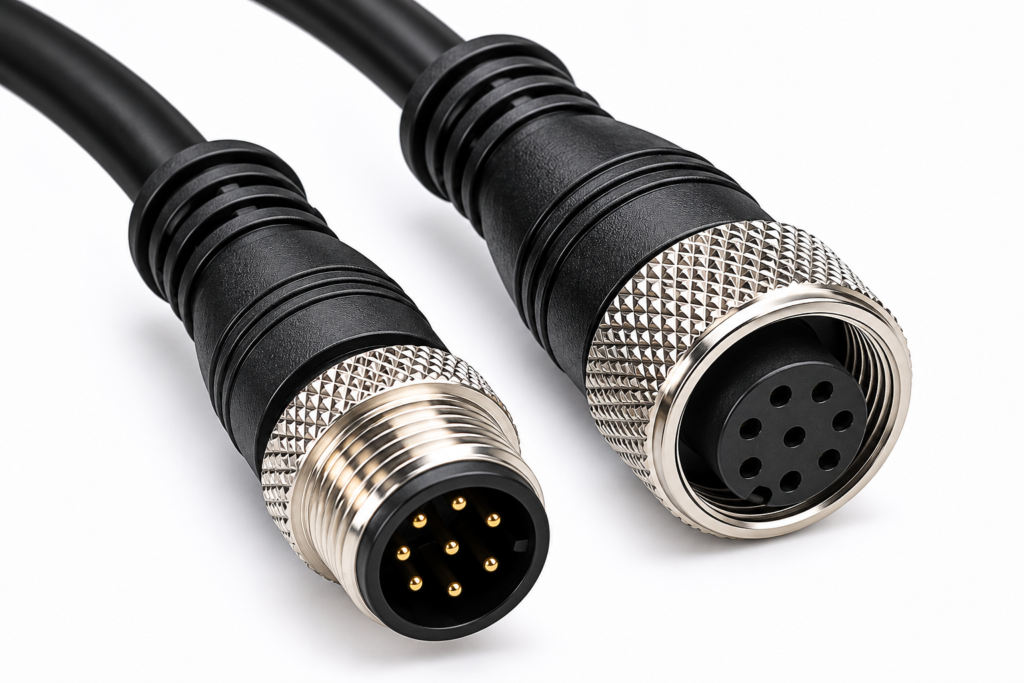
Connector Type and Coding
“M8 to M12” identifies two connector families, but it does not completely identify a cable assembly. Within these families, industrial connector systems can use different numbers of contacts, different keying or coding arrangements and different mating configurations. A project description should therefore identify which connector is required on each end, whether it is male or female, how many positions are required and which coding applies to the equipment.
A-coded configurations are commonly encountered in sensor and actuator applications, while other M12 coding families are used for different signal, data or power purposes. Even within one coding family, several contact counts can exist. The safest purchasing practice is to provide the exact approved connector part number whenever engineering has already selected one. If no part number is available, connector photographs, drawings and mating-device information give the manufacturer useful references for confirming the interface.
Connector diameter should never be treated as the full specification. Two connectors can both be described as M12 while differing in coding, contact arrangement or mating design. A quotation may therefore look complete commercially while still being technically wrong if the underlying connector selection was based on appearance alone.
Gender, Orientation and Cable Exit
Male versus female is usually easy to confirm from a controlled drawing, but connector orientation deserves just as much attention. Straight connectors are practical when there is enough clearance behind the sensor, actuator or control device. Right-angle connectors are useful when a cable must turn immediately after the connection point or when equipment space is restricted.
The challenge is that “right-angle” can still be incomplete information. Once the threaded connector is fully mated, the cable exit needs to point toward a usable routing path. On compact machines, sensor clusters and enclosed automation systems, an incorrect exit direction can cause interference with adjacent hardware even though the connector itself is technically correct.
For installations with restricted clearance, an equipment photo or installation drawing marked with the intended cable direction can prevent unnecessary sample revisions. It is also useful to identify where cable length should be measured from, because the measurement reference can change when molded straight and angled connectors use different body dimensions.
Mating Interface and Part Numbers
The mating interface provides another important verification point. If the M8 connector will attach to a known sensor and the M12 connector will attach to a known I/O module, controller or panel receptacle, include those device models or connector part numbers in the RFQ. This is especially useful when replacing an existing assembly that has no readable cable label or controlled drawing.
An old cable can be a valuable sample, but appearance alone should not become the permanent production specification. A manufacturer can use the sample together with mating-component information, connector dimensions and pinout verification to rebuild a controlled reference for future samples and repeat orders. That makes later engineering changes easier to manage and reduces dependence on one physical reference sample.
When an exact connector brand or manufacturer part number is mandatory, the BOM should identify it clearly. If compatible alternatives may be reviewed, the customer should identify which characteristics cannot change, such as mating interface, dimensions, electrical characteristics, material requirements or required documentation.
Connector Protection and Overmolding
Connector protection can also change the scope of a quotation. A standard molded connector, a field-wireable connector and a custom overmolded connector are different manufacturing tasks. A project may require only an existing molded connector structure, while another project may need custom tooling, a longer strain-relief section, a particular cable-exit shape or a molded body designed around limited installation space.
Overmolding should be discussed first as a functional requirement. The important questions are whether it needs to protect the connector-to-cable transition, improve strain relief, contribute to sealing, control the cable exit or meet an appearance requirement. If dimensions, hardness, color, logo position or material are controlled, these items should be included in the project files before tooling begins.
For a custom cable project, connector type, molded shape, cable-exit direction, material, sealing requirement and sample approval method should be considered together. This avoids the common situation in which the electrical cable has already been quoted but the tooling and molded structure that make the assembly usable were never included.
| Connector Item | Information to Provide | Selection Value | Risk if Missing |
| Connector family | M8 end and M12 end | Establishes interface family | Wrong connector selected |
| Gender | Male or female on each end | Confirms mating relationship | Cable cannot connect |
| Pin count | Exact number of contacts | Defines circuit capacity | Incorrect wiring structure |
| Coding | Required project coding | Controls keying compatibility | Mechanical mismatch |
| Orientation | Straight or right-angle | Controls routing | Installation interference |
| Part number | Approved connector PN | Minimizes interpretation | Unapproved substitute |
| Mating part | Sensor or equipment interface | Supports compatibility check | Sample fits drawing but not device |
| Shielding | Shielded or unshielded requirement | Defines connector termination | Incomplete shield path |
| Overmolding | Standard or custom | Defines tooling/process | Missing tooling cost |
| Sealing requirement | Defined project requirement | Guides structure review | Unsupported waterproof assumption |
Which Cable Specifications Must Be Confirmed?
The cable portion should be defined by finished length, tolerance, conductor count and size, jacket material, shielding, outside-diameter constraints and mechanical duty. The correct cable is not automatically the thickest, most flexible or most expensive option. It is the structure that fits the connector termination, electrical load, installation route, environmental exposure and expected movement of the equipment.

Length, Tolerance and Routing
Finished cable length is one of the first figures requested during quotation, but a number such as “2 m” is not always enough. The customer and manufacturer should agree on where the measurement starts and ends. Depending on the assembly drawing, length may be controlled between connector reference faces, molded-body reference points or another defined feature.
Routing can be just as important as nominal length. The shortest straight-line distance between two pieces of equipment rarely represents the actual cable route through a machine. A cable may need to follow a frame, pass through a cable tray, bend around a protective cover or leave additional slack so the connector is not subjected to constant tension.
Commercial industrial sensor cable families are offered in many lengths, from short sub-meter assemblies to cables extending tens of meters. These commercial ranges demonstrate that cable length is a normal configuration variable rather than a universal standard. For custom projects, the equipment drawing and actual routing should determine the required length rather than copying a common catalogue size.
Where several versions are required, list every length as its own SKU and provide realistic quantities. This makes material planning, inspection, labeling and packaging much clearer during production.
Conductors and Wire Size
Wire gauge or conductor cross-sectional area should be supplied whenever the equipment design already defines it. If the conductor has not yet been selected, the manufacturer needs enough application information to review the requirement properly, including current, voltage, circuit type, connector structure and routing constraints.
Increasing conductor size does more than increase electrical capacity. It can increase finished cable diameter, reduce flexibility and change how easily the individual conductors can be terminated inside the connector. Compact M8 interfaces in particular can impose mechanical limits on conductor and cable dimensions, so the cable structure and connector should be reviewed together.
The number of conductors should follow the actual electrical circuit rather than automatically matching the number of connector positions. Some projects leave one contact unused, use a dedicated shield or drain connection, or require application-specific wiring. A proper review therefore considers conductor count, wire size, insulation, finished cable diameter, connector termination and pinout as one system instead of separate purchasing choices.
Jacket and Material Choice
PVC and PUR are both widely encountered in industrial sensor and automation cables, but material selection should follow the real application. PVC can be suitable for many general-purpose or relatively static installations, while PUR is often considered where abrasion, flexibility or oil exposure is more important. Neither material should be treated as automatically correct for every M8-to-M12 cable.
The material name alone also does not establish every performance characteristic. Temperature range, resistance to particular oils, weathering, repeated flexing and other properties depend on the exact compound, cable structure and applicable test conditions. For that reason, a project requiring a specific environmental performance should define the target requirement rather than simply requesting “PUR industrial cable.”
A useful RFQ describes where the cable will actually work: inside a dry control cabinet, on a factory machine, near oil or coolant, outdoors, close to moving parts or in another controlled environment. That context gives engineering a better basis for material selection and reduces the chance of paying for unnecessary performance or choosing a material that does not address the real risk.
Shielding and Flexibility
Shielding is another cable variable that should never be inferred from the connector name. M8 and M12 sensor cable assemblies can be produced in shielded or unshielded constructions depending on the electrical environment and signal requirements. If electromagnetic interference is a concern, the RFQ should identify whether foil shielding, braided shielding or another specified structure is required and how the shield should terminate.
Flexibility also needs a more precise definition than the phrase “flexible cable.” A cable that bends during installation is different from one that moves occasionally during maintenance, and both are different from a cable that repeatedly moves with automation equipment. Dynamic use may require a different conductor, insulation, jacket and strain-relief design.
Where repeated motion is involved, provide the bend location, available bend radius, movement pattern and any defined cycle requirement. This allows the manufacturer to review the complete mechanical duty instead of choosing a material based only on a broad description.
| Cable Variable | Common Inputs | Main Selection Question | Quotation Impact |
| Finished length | Project-defined | Where are measurement reference points? | Material consumption |
| Length tolerance | Drawing-defined | Is routing tightly controlled? | Cutting and inspection |
| Conductor count | Circuit-defined | How many active circuits are needed? | Cable construction |
| Wire size | AWG or mm² | What current and signal requirements apply? | Material and OD |
| Jacket | PVC, PUR or project material | What environment will it face? | Material cost |
| Shielding | None, foil, braid | Is EMI protection needed? | Material and termination |
| Cable OD | Connector or installation controlled | Must it pass through restricted space? | Connector compatibility |
| Mechanical duty | Static to repeated movement | How often does it bend? | Structure and validation |
| Color | Standard or project-defined | Is identification important? | SKU/material planning |
| Environment | Indoor, oil, outdoor, machinery | Which hazards are relevant? | Material/test selection |
How Should Pinout and Electrical Requirements Be Defined?
The electrical specification should show exactly how each conductor connects between the M8 and M12 ends. A controlled pinout should identify pin-to-pin mapping, wire colors or conductor IDs, circuit function, unused contacts, crossed wiring, bridges, polarity and shield termination. Where electrical load matters, operating voltage and current should also be provided. Physical connector compatibility alone cannot prove electrical compatibility.

Pin-to-Pin Mapping
A pinout table is often the most efficient way to remove electrical ambiguity. It should identify the M8 contact, conductor or wire color, circuit function and corresponding M12 contact. This is far safer than assuming that an M8-to-M12 cable automatically uses straight-through wiring.
Some assemblies may connect pin 1 to pin 1, but others may use a different assignment because the devices on either side follow different interface requirements. Crossed connections, unused positions, shared connections or a shield termination can all change the actual production structure.
For this reason, a manufacturer should not invent a universal M8-to-M12 pinout. The controlled customer drawing, equipment schematic or approved pin table remains the correct source. If the project begins from an old sample, continuity measurements can help reconstruct the existing wiring, but engineering should still approve the resulting pinout before it becomes a production reference.
A clear pin table also helps quality teams configure continuity and wire-sequence testing later, giving the same specification a useful role from quotation through mass production.
| M8 Pin | Conductor ID | Circuit Function | M12 Pin | Review Status |
| Pin 1 | Customer-defined | Customer-defined | Customer-defined | Confirm |
| Pin 2 | Customer-defined | Customer-defined | Customer-defined | Confirm |
| Pin 3 | Customer-defined | Customer-defined | Customer-defined | Confirm |
| Pin 4 | Customer-defined | Customer-defined | Customer-defined | Confirm |
| Shield | Drain/braid if required | Shield path | Shell or specified contact | Confirm |
Power, Signal and Current
Where possible, each conductor should have an identified function. A sensor cable may contain supply, ground and signal circuits, while more complex equipment can contain additional control lines or application-specific assignments. Describing circuit function helps engineering identify inconsistencies between pinout, conductor size and electrical load.
Voltage and current should be included when they affect wire size, insulation requirements or connector contact suitability. M8 and M12 describe mechanical interface families rather than one fixed electrical rating. Different connector designs, coding families and contact configurations can support different electrical requirements, so the customer’s actual system specification should control the design.
If one pair of conductors carries a higher current while other cores carry low-level signals, identify that distinction. It may influence conductor selection, shielding and termination. A quotation based only on the connector name cannot reliably account for those differences.
When the equipment specification is still evolving, it is safer to mark voltage, current or circuit assignments as pending rather than enter provisional figures that may later be mistaken for approved production data.
Special Wiring Conditions
Small wiring exceptions often cause disproportionate problems in production. A single bridged contact, intentionally unused pin, polarity requirement or crossed conductor can turn a visually perfect assembly into a cable that fails immediately on the equipment.
Unused contacts should be marked clearly instead of being left blank. If two pins are intentionally bridged, show that bridge in the drawing. If wire colors follow a customer-specific convention, include it in the specification. Where shielding is used, document whether the drain or braided shield terminates at a shell, dedicated contact, one end only or another defined point.
Replacement projects deserve extra caution because a physical sample may contain previous engineering revisions, repairs or undocumented changes. When an approved schematic exists, it should take precedence over assumptions drawn from appearance. Where only a known-good sample is available, its electrical mapping should be documented and approved before it becomes the master production reference.
Verification Before Production
Electrical verification is most reliable when specification approval and production testing are treated as two different steps. Engineering first defines what the cable is supposed to do. Testing then verifies whether the manufactured cable matches that definition.
A continuity tester can identify opens, shorts and incorrect connections, but it cannot decide whether the customer’s original pinout was conceptually correct. That is why the pinout, wire sequence and polarity should be approved before sample production and test fixtures are prepared around that approved reference.
For repeat orders, the final drawing, BOM, pinout and approved sample should remain under revision control. If a sensor, controller or I/O module is replaced with a new generation, procurement should confirm that the mating connector and electrical assignment have not changed before placing a repeat order against an old cable revision.
| Electrical Input | Useful RFQ Information | What It Helps Confirm | Main Risk if Missing |
| Pinout | M8-to-M12 mapping | Wiring correctness | Functional mismatch |
| Wire colors | Color by circuit | Identification | Troubleshooting errors |
| Circuit function | Power, signal, ground, control | Structure review | Wrong conductor choice |
| Voltage | Actual system requirement | Insulation/contact review | Electrical mismatch |
| Current | Current by circuit | Wire/contact selection | Heating or voltage drop |
| Polarity | Positive/negative assignment | Power orientation | Device malfunction |
| Unused pins | NC designation | Production clarity | Accidental connection |
| Shield termination | Defined endpoint | Shield construction | Incomplete EMC path |
| Bridges | Defined connections | Special circuit function | Equipment failure |
| Revision | Approved drawing version | Document control | Wrong version produced |
What Application and Test Conditions Affect the Quote?
Application conditions influence jacket material, shielding, connector protection, strain relief, cable flexibility and the test plan. An RFQ should describe where the cable will be installed, whether it moves, what mechanical or environmental exposure it faces and which acceptance criteria are required. “Industrial grade” is too broad to define a reliable assembly; actual operating conditions produce a much more useful quotation.

Installation Environment
Industrial use covers very different operating conditions. A sensor cable permanently installed inside a protected enclosure has a different duty from a cable routed around an automated machine where it is exposed to abrasion, movement, oil, washdown or repeated maintenance.
A useful RFQ identifies the actual device and installation. Examples may include proximity sensors, photoelectric sensors, actuators, machine I/O, control equipment, inspection machinery or custom automation systems. It should also indicate whether the cable is mounted inside or outside an enclosure and whether it runs close to motors, drives or other potential interference sources.
This context helps engineering decide whether shielding, a particular jacket structure, enhanced strain relief or another construction feature is worth considering. It also reduces the temptation to add expensive features simply because a purchasing description uses the word “industrial.”
The goal is to match the cable to the machine rather than select the most complicated construction available.
Moisture, Oil and Mechanical Exposure
Environmental protection should be defined through real conditions or a specified acceptance requirement. The word “waterproof” by itself is not precise enough to determine connector design, sealing structure or testing.
Commercial M8 and M12 products are available with published ingress-protection ratings, but those ratings apply to particular connector designs, mating conditions and validated products. A custom cable should therefore be reviewed against its own connector, overmold structure, mating component and required test method instead of inheriting a rating from an unrelated catalogue product.
The same principle applies to oil resistance, temperature range, UV exposure and chemical contact. A material name such as PUR may suggest a useful direction, but final performance depends on the compound and defined test conditions.
It is far more useful to state that the cable is exposed to cutting fluid, periodic washdown or outdoor weather than to request a generic “heavy-duty cable.” Specific operating information gives engineering something measurable to evaluate.
Movement and Strain Relief
Movement can completely change the appropriate cable construction. A cable that bends only once during installation may not require the same conductor, jacket or strain-relief design as one that moves continuously with automation equipment.
If movement is expected, describe where the bend occurs, how frequently it moves, the approximate bend radius and any existing cycle requirement. Repeated motion close to the connector is especially important because the cable-to-connector transition tends to concentrate mechanical stress.
Strain relief can distribute this stress over a longer transition area and reduce sharp bending immediately next to the connector body. The shape, length and flexibility of the molded transition should therefore be selected according to use rather than appearance alone.
Where the cable follows a moving axis or experiences repeated machine cycles, the sample and qualification stage may also need additional mechanical validation. A clear movement description at RFQ stage prevents a static cable from being quoted for a dynamic application simply because both versions use the same M8 and M12 interfaces.
Testing and Acceptance Criteria
Testing should follow the actual project risks. An assembly where wiring accuracy is critical may emphasize continuity and pinout verification. A cable exposed to pulling forces may require defined pull-force validation. A repeatedly moving assembly may need bending or swing testing, while environmental applications can call for temperature, humidity, corrosion or sealing-related evaluation.
The important point is to state the test requirement and acceptance criterion rather than use broad phrases such as “high quality” or “fully tested.” “100% continuity test against approved pinout” provides a much clearer production requirement than “100% tested.”
Depending on product structure and project specifications, industrial cable testing can include continuity, connector-fit, pull-force, bending, tensile, insulation, salt-spray, temperature/humidity or other agreed checks. These tests should not automatically be added to every cable. Each additional test should address a real application risk or customer requirement.
A defined test plan also improves purchasing comparisons because quotations from different manufacturers can be evaluated against the same quality expectations.
| Application Condition | Information to Share | Engineering Question | Possible Validation |
| Static sensor connection | Route and environment | Is standard construction sufficient? | Continuity / fit check |
| Repeated movement | Bend point and cycle requirement | Is dynamic construction needed? | Bending / swing test |
| Pulling force | Expected load | Is strain relief adequate? | Pull-force / tensile test |
| Vibration | Machine operating condition | Will transition see repeated stress? | Application-specific review |
| Moisture | Target protection requirement | How should sealing be designed? | Sealing test |
| Oil exposure | Fluid and exposure condition | Is jacket material suitable? | Material evaluation |
| EMI-sensitive signal | Shield requirement | How should shielding terminate? | Shield continuity |
| Outdoor use | UV/weather/temperature needs | Which jacket and sealing apply? | Environmental testing |
| Corrosive environment | Exposure condition | Are metal parts at risk? | Salt-spray test |
| Temperature variation | Defined temperature conditions | Are materials appropriate? | Temperature/humidity test |
What RFQ Files and Order Details Are Needed?
A useful RFQ combines engineering information with practical purchasing details. Drawings, BOMs, connector references, pinout, cable length, application, quantities, testing, labels, packaging and destination allow the manufacturer to evaluate the whole project instead of only the cable itself. A complete drawing is ideal, but projects can still begin from samples, photographs and known equipment information when missing items are clearly identified.

Drawing, BOM and Sample References
A controlled drawing is usually the most efficient project reference because it can combine cable length, connector orientation, pinout, tolerances, molded dimensions, labeling and revision information on one document. A BOM adds exact connector, cable, terminal or material references where engineering has already selected specific components.
Revision status is essential. A manufacturer can quote every requirement correctly and still supply the wrong assembly if purchasing sends an outdated drawing. The RFQ should therefore identify the current drawing and BOM revision and clearly mark any files that are still provisional.
Where approved connector part numbers are mandatory, they should appear directly in the BOM. If equivalent parts may be considered, define the characteristics that must remain unchanged rather than simply asking for an “equivalent connector.”
An existing sample is especially useful for replacement projects. It can provide dimensions, connector geometry, cable feel and wiring references, but the long-term goal should be to convert that physical sample into controlled documentation that can support future engineering changes and repeat orders.
When Drawings Are Incomplete
Not every project starts with a complete engineering package. Early product development may begin with connector photographs, equipment information and an approximate cable route, while replacement projects may begin with only an existing cable sample.
Useful early-stage information can include clear photographs of both connector ends, visible part markings, mating equipment models, required cable length, cable jacket markings, approximate outside diameter, known conductor information, target pinout, application and expected quantity.
The important distinction is between confirmed and unknown information. An open requirement should remain visibly open rather than being replaced with a convenient assumption. A preliminary quotation can identify assumptions, but those assumptions need to be resolved before final sampling, tooling or mass production.
This approach often reduces email cycles because engineering teams can work from one shared list of open items. Instead of repeatedly asking whether the cable is “similar to the photo,” both sides can gradually turn the initial reference material into a controlled specification.
Quantity and Commercial Planning
Quantity affects component purchasing, cable preparation, production setup, tooling allocation, packaging and inspection planning, so realistic volume information should be included even during technical RFQ preparation.
Where a project moves through several stages, distinguish prototype, pilot and production quantities rather than combining them into one optimistic annual forecast. If multiple cable lengths, connector orientations or pinouts belong to one program, provide quantity by SKU. A project containing several thousand assemblies across ten variants can require very different planning from the same total quantity concentrated in a single SKU.
Cablivo’s objective project information states that MOQ starts from 500 pieces for many custom cable projects, while the final requirement depends on connector type, cable structure, material, overmolding, tooling, packaging and order quantity.
Clear volume information produces a quotation that purchasing teams can compare more realistically and gives production teams a better basis for planning materials, testing and packaging.
Labeling, Packaging and Delivery
A cable project is not complete when the assembly passes electrical testing. Cable labels, customer part numbers, wire-number labels, barcode requirements, protective packaging, SKU separation, carton marks and export packing can all become part of the production specification.
This is especially important for programs containing multiple visually similar assemblies. Two cables may have the same connector families but different lengths or pinouts. Clear labeling reduces receiving errors, warehouse confusion and incorrect installation at the customer’s facility.
Packaging should also protect the connectors themselves. Exposed mating surfaces, threaded bodies and long cable assemblies can be damaged or tangled when packed without an agreed method. Individual bags, protective caps, controlled coil dimensions or special cartons should be discussed before the final production quotation when they are required.
Shipping destination and desired project timing should also be included. Material availability, connector sourcing, tooling, testing, packaging and order quantity can all influence production scheduling, so delivery expectations become more reliable after the technical specification is stable.
| RFQ Item | Preferred Input | Early-Stage Alternative | Required Before Production |
| Drawing | Controlled drawing with revision | Marked sketch | Yes |
| BOM | Approved component list | Key connector references | Yes |
| M8 connector | Exact part number | Photo + mating interface | Yes |
| M12 connector | Exact part number | Photo + mating interface | Yes |
| Pinout | Approved wiring table | Known-good sample | Yes |
| Cable length | Dimension + reference points | Measured sample | Yes |
| AWG / conductors | Drawing specification | Electrical data for review | Yes |
| Jacket | Material specification | Application description | Yes |
| Shielding | Defined structure | EMI requirement | Yes |
| Application | Equipment description | Equipment photos | Recommended |
| Testing | Test method and criteria | Risk description | Yes |
| Quantity | Quantity by SKU | Prototype + forecast | Required for quote |
| Labels | Approved artwork/rule | Label concept | Yes |
| Packaging | Packing specification | Reference photos | Yes |
| Destination | Shipping destination | Target market | Required for logistics |
| Timing | Project requirement | Preferred schedule | Confirm after review |
| Revision | Current file revision | Pending revision marked | Final revision required |
A final RFQ review should separate confirmed requirements from open questions. Connector type, gender, coding, orientation, pinout, cable length, conductor construction, jacket, shielding, application environment, mechanical duty, testing, quantity, labeling and packaging should either be confirmed or clearly identified as provisional. This gives engineering, purchasing and production teams the same reference and prevents a preliminary price based on assumptions from being mistaken for a final production quotation.
Cablivo is the overseas-facing brand of Shenzhen Tianxiaowei Electronics Co., Ltd., supporting custom cable, wire harness and cable assembly projects through requirement review, drawing and connector confirmation, sample development, production, testing, packaging and shipment coordination. Its documented manufacturing positioning is focused on project-based custom cable programs rather than low-end spot cable trading.
For an M8-to-M12 cable assembly project, you do not need to wait until every engineering document is perfect before starting a technical discussion. A drawing, existing sample, connector photographs, BOM, mating-part information, target length, pinout, application, quantity and testing requirements can provide enough information for an initial review. Missing items can then be identified and confirmed systematically before sampling and mass production.
A good quotation does more than put a unit price beside a cable. It creates a controlled path from interface confirmation and wiring review to sample approval, production testing, labeling, packaging and repeat supply. For a cable sitting between an industrial sensor and the machine that depends on its signal, that level of clarity is far more useful than a quotation built from only three words: “M8 to M12.”



