 Skip to content


An equipment wire harness can look surprisingly simple when it is lying on a table: several wires, a few connectors, protective sleeving, labels, and perhaps an overmolded transition. A manufacturer, however, cannot build a reliable quotation from appearance alone. The real cost sits inside the details—the exact connectors and terminals, wire specifications, circuit mapping, branch dimensions, equipment environment, assembly processes, testing requirements, labeling, packaging, and expected production quantity.
An accurate equipment wire harness quote normally requires a drawing or sample reference, BOM, connector and terminal information, pinout, wire sequence, wire gauge, cable and branch lengths, application conditions, target quantity, testing requirements, labeling, packaging, and shipping information. When complete drawings are unavailable, clear sample photos and known specifications can start an engineering review while missing details are identified.
Imagine three factories receiving the same photograph of an existing harness. One assumes a locally available connector, another prices the original connector family, and the third assumes a different cable jacket and no electrical test beyond continuity. All three quotations may look professional, but they are not prices for the same product. A useful RFQ does more than ask for a number; it creates enough technical clarity that different suppliers are actually evaluating the same equipment wire harness.
What Files Are Needed for a Quote?
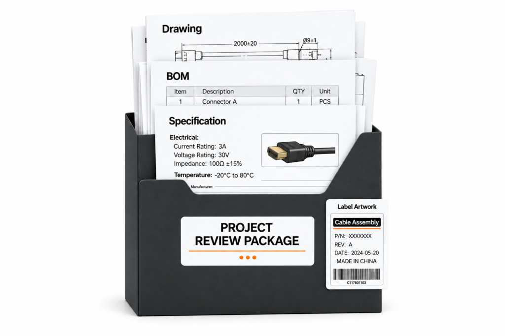
A reliable quotation package normally includes a controlled wire harness drawing, BOM, pinout or wiring table, connector information, testing requirements, and any packaging specifications that affect the finished assembly. These documents define the physical structure, materials, electrical relationships, acceptance criteria, and current revision so the manufacturer can quote the intended harness rather than a product built around assumptions.
Image for This H2
Image Type: Project Documentation Composition
Image Direction: Show a complete real equipment wire harness RFQ package on an engineering workbench: finished wire harness, engineering drawing sheets, BOM, pinout reference, connector samples, and packaging reference. The image should make the relationship between the physical product and its documentation immediately understandable without displaying readable specifications.
Image Prompt: Real equipment wire harness RFQ package with finished wire harness, engineering drawing sheets, BOM documents, pinout reference, connector samples and packaging reference arranged neatly on an industrial engineering desk, realistic product photography, professional industrial website style, clean background, natural lighting, 16:9 aspect ratio, high resolution, sharp product details, no text, no logo, no watermark
Negative Prompt: text, logo, watermark, abstract concept image, fake 3D render, CGI look, wrong product structure, incorrect assembly, floating parts, distorted proportions, unrealistic materials, exaggerated lighting, low resolution, blurry details
Alt Text: Wire harness quotation package with drawings BOM pinout and connector reference samples
Harness Drawing
A useful wire harness drawing should make the physical assembly understandable without requiring the manufacturer to reconstruct the product from guesswork. For a simple point-to-point harness, this may include the overall length, connector positions, wire specification, and terminal information. For a multi-branch equipment harness, each leg should normally have a clear reference, branch length, breakout location, connector orientation, protective treatment, and any dimensions that influence installation inside the machine.
Length definition deserves particular attention because a single overall dimension may hide several critical branch relationships. A sensor branch may need to reach a moving component while another branch terminates inside a fixed control enclosure. If only one or two dimensions are functionally critical, the drawing should identify them rather than applying unnecessarily tight tolerances to the entire harness. Excessively tight dimensions may increase inspection and production effort without adding practical value.
The drawing should also identify protective components such as braided sleeve, corrugated tubing, heat shrink, tape, clips, grommets, cable ties, boots, or overmolded transitions where those features influence the finished construction. Connector exit direction can be equally important. A connector with the correct part number and pinout may still make the harness unusable if it exits toward a cabinet wall or prevents the installer from routing the cable through the intended path.
| Drawing Item | Useful RFQ Information | Quotation Impact | Typical Risk if Missing |
| Overall length | End-to-end dimension | Wire consumption and cutting | Price based on assumed length |
| Branch length | Length of each harness leg | Material and assembly effort | Branch cannot reach equipment |
| Breakout point | Position from a defined datum | Harness geometry | Incorrect branch location |
| Connector orientation | Direction and clocking | Installation and assembly | Connector interferes with equipment |
| Sleeve or conduit | Type and coverage length | Material and processing | Inadequate or excessive protection |
| Label position | Location from connector or branch | Identification process | Installation confusion |
| Critical tolerance | Only dimensions that truly matter | Inspection effort | Unnecessary manufacturing cost |
| Drawing revision | Current released revision | Defines quoted version | Obsolete configuration quoted |
Cablivo’s project guidance treats drawing review as an engineering activity rather than a simple document check. The review can cover cable length, connector type, AWG, pinout, wire sequence, materials, labeling, testing, and packaging details before quotation or sampling, helping bring the mechanical drawing into alignment with the actual manufacturing definition.
BOM Details
The drawing explains where components go; the BOM explains exactly what those components are. A useful equipment wire harness BOM can include connector housings, terminals, seals, secondary locks, wires, multi-core cables, sleeves, heat-shrink tubing, conduit, tape, clips, labels, overmold materials, grommets, and relevant packaging components. Exact manufacturer part numbers are especially useful for components that affect mating compatibility or customer qualification.
Descriptions such as “4-pin waterproof connector” are often insufficient because several connector families can look nearly identical while using different keying arrangements, terminal systems, seals, plating, or mating interfaces. A quotation based on a generic visual equivalent may initially look competitive but can change significantly once the specified connector and terminal numbers are confirmed. The same issue occurs when a BOM identifies only “18 AWG black wire” without defining the insulation material or required wire series.
The BOM also gives procurement teams visibility into sourcing risk. A connector can be technically correct but subject to high minimum purchasing quantities, limited distribution, long replenishment cycles, or customer-controlled sourcing. Those conditions can influence prototype feasibility, initial order cost, and production lead time without changing the visible harness design. Reviewing such issues before sampling is usually more efficient than discovering them after an approved design has already been locked.
| BOM Item | Better Definition | What It Helps Confirm |
| Connector housing | Manufacturer and exact P/N | Interface and sourcing |
| Terminal | Exact P/N and compatible wire range | Crimp process |
| Seal | P/N or approved sealing system | Environmental interface |
| Wire | AWG, material, color, approved series | Electrical and processing requirements |
| Sleeve | Material, diameter, coverage | Mechanical protection |
| Heat shrink | Size, material, location | Insulation and finishing |
| Label | Artwork, material, position | Identification |
| Clip or grommet | P/N and installation location | Equipment mounting |
| Overmold material | Required material or performance | Strain relief and protection |
| Packaging component | Bag, cap, divider, carton | Shipment preparation |
For BOM-based projects, Cablivo’s documented review can include connectors, terminals, wire specifications, materials, labels, packaging components, and potential sourcing risks before quotation or sampling.
Wiring and Pinout Files
A mechanical drawing can show that two connectors are physically linked, but it does not always show what every conductor does electrically. Multi-circuit equipment harnesses therefore benefit from a dedicated pinout, wire list, schematic reference, or connection table that traces every active cavity from its source connector to the correct destination. The format can be simple as long as the electrical relationships are unambiguous.
A practical wiring table may identify connector reference, cavity number, circuit name, wire color, AWG, destination connector, destination cavity, and any shield or ground relationship. This becomes especially important when several conductors share the same insulation color or when a branch divides one source circuit across multiple endpoints. Power, ground, sensors, communication pairs, control signals, and shield connections should never depend solely on visual interpretation.
Pinout information also becomes the master reference for electrical testing. Continuity and miswire testing can confirm that the manufactured harness matches the approved electrical definition, but those tests cannot determine whether an incorrect customer pinout was logically correct for the equipment. Before a production test fixture becomes useful, the electrical specification itself must first be confirmed.
| Connector | Pin | Circuit | Wire | Destination | Destination Pin |
| A | 1 | Power + | 18 AWG red | B | 1 |
| A | 2 | Ground | 18 AWG black | B | 2 |
| A | 3 | Sensor signal | 22 AWG | C | 1 |
| A | 4 | Sensor return | 22 AWG | C | 2 |
| A | 5 | Communication + | Twisted pair | D | 3 |
| A | 6 | Communication – | Twisted pair | D | 4 |
The values above illustrate the type of information that is useful rather than a universal equipment specification. Actual conductor sizes, circuit names, and connection sequences should always follow the customer’s electrical design and applicable equipment requirements.
Revision Control
Revision control prevents technically correct quotations from being prepared against the wrong product. The drawing, BOM, wiring table, label artwork, and test specification should therefore carry identifiable revisions, and the RFQ should make it clear which combination of documents is current. When engineering changes a connector, branch dimension, wire gauge, protective structure, or pin assignment, the revised package should replace earlier files instead of circulating alongside them with unclear file names.
This matters most when several manufacturers are being compared. A five-percent price difference has little meaning if one manufacturer quoted an older revision with fewer protective components while another quoted the latest release with a changed connector and additional testing. A fair comparison requires a common technical baseline.
Revision control also becomes important after sampling. Once the project team approves the physical sample, the released drawing, BOM, pinout, label files, and test plan should reflect the approved construction. That alignment reduces the chance of a sample-to-production mismatch caused by factory personnel building from documentation that does not fully represent the version engineering actually validated.
Which Electrical Details Must Be Confirmed?
An accurate equipment wire harness quotation should clearly define connector housings, terminals, pinout, wire sequence, conductor size, insulation or jacket requirements, shielding, and any circuit-specific electrical conditions. These details determine component cost, terminal compatibility, assembly operations, electrical testing, and whether the final harness will mate with the intended equipment and connect every circuit correctly.

Connectors and Terminals
Connector confirmation should go beyond identifying the number of pins. A complete interface may include the connector housing, terminals, wire seals, cavity plugs, secondary locks, backshells, clips, protective boots, and the mating component fitted to the customer’s equipment. When these details are specified, manufacturer and part number information provides a much stronger quotation basis than a photograph or generic connector description.
Terminal compatibility is especially important because the correct terminal usually needs to match the connector family, conductor cross-section, insulation diameter, crimp geometry, and sometimes plating requirement. A terminal intended for a smaller conductor range can produce an unreliable crimp if used with a larger wire, while a seal designed for a different insulation diameter may fail to compress correctly in a sealed connector.
Availability should also be discussed before the quotation is treated as final. Some connector families are easy to source globally, while others may be restricted to certain channels or require purchase quantities far above the harness order. When approved equivalent components are acceptable, that flexibility should be stated. When the exact part number is mandatory, the quotation should be based on that component rather than a lower-cost assumed substitute.
| Connector Detail | Information to Confirm | Project Impact |
| Housing | Manufacturer + P/N | Correct mating interface |
| Terminal | P/N and wire range | Crimp quality |
| Seal | Correct wire OD range | Sealing performance |
| Mating part | Equipment-side P/N | Compatibility |
| Pin count | Active and unused cavities | Electrical layout |
| Orientation | Keying and exit direction | Installation fit |
| Plating | If controlled by project | Electrical/contact requirement |
| Approved alternative | Allowed or prohibited | Cost and availability |
| Shield termination | Shell, pin, drain, chassis | EMC implementation |
Connector confirmation in Cablivo’s engineering fact library can include model, pin count, mating part, direction, terminal match, waterproof requirements, shielding needs, and sourcing availability.
Pinout and Wire Sequence
Pinout defines the electrical logic of the harness. A simple two-wire power lead may have only positive and negative conductors, but a machine harness can combine power circuits, sensors, communication pairs, ground paths, switches, motors, and control signals within the same assembly. Each connector cavity should therefore have a clearly identified destination so the manufacturer can trace the entire electrical path without guessing.
Color helps operators distinguish conductors during assembly, but color alone should not be the primary electrical definition for a complex harness. Pin references and circuit identification are more reliable, especially when multiple same-color wires are used or when circuit markers are printed onto individual conductors. If a signal branches into two destinations, the electrical document should show that split explicitly rather than relying on the physical drawing to imply it.
Once the circuit map is approved, it can be translated into production test logic. Electrical test equipment can then check opens, shorts, and incorrect wiring against the defined harness circuit. Cablivo’s documented engineering scope includes both wire-sequence confirmation and pinout review, which are particularly relevant before sample development and production preparation.
Wire Gauge and Materials
AWG is one of the first specifications procurement teams often mention, but gauge alone is not enough to define a conductor. Common harness projects may use sizes such as 18, 20, 22, or 24 AWG, with larger conductors on higher-current circuits and smaller conductors on controls or signals. Those sizes are examples of common industry practice rather than a recommendation for a particular piece of equipment.
The correct wire size depends on current, voltage drop, conductor temperature, circuit length, bundle conditions, terminal limits, and the equipment’s applicable design requirements. A longer power circuit may need different consideration from a short internal signal line even when both appear in the same harness. The terminal system also places practical limits on the conductor and insulation diameter that can be processed.
Insulation and jacket materials require similar application-based thinking. PVC, TPE, TPU, PUR, silicone, PE, XLPE, and other materials can provide different combinations of flexibility, abrasion behavior, temperature capability, oil-related performance, or processing characteristics. The correct choice should follow the real environment rather than a generic preference for a material described as “premium.”
| Parameter | Examples of Information to Provide | Selection Consideration |
| Wire size | AWG or mm² | Current, voltage drop, terminal range |
| Conductor | Bare or tinned copper if specified | Electrical and environmental needs |
| Insulation | PVC, PE, XLPE, silicone, others | Temperature and application |
| Jacket | PVC, TPE, TPU, PUR, others | Flexibility, abrasion, environment |
| Wire color | Customer circuit color scheme | Assembly and maintenance |
| Temperature | Actual required operating range | Material selection |
| Flexibility | Fixed or moving installation | Conductor and jacket construction |
| Shielding | Foil, braid, combined | Signal environment |
| Approved wire | Manufacturer + P/N when mandatory | Sourcing and compliance |
Cablivo’s material guidance covers conductor, insulation, shielding, jacket, sleeve, heat-shrink, and overmold structures according to product type and project needs rather than treating one material system as suitable for every application.
Shielding and Circuit Protection
Shielding should solve an actual signal or electromagnetic problem rather than being added automatically to make the harness appear more industrial. Foil shielding can provide broad coverage around a conductor group, while braided shielding offers a different mechanical and electrical structure. Some projects combine foil and braid where the electrical design requires it, but the correct construction depends on signal type, frequency behavior, equipment grounding, cable movement, and the overall EMC strategy.
The way the shield terminates can be just as important as the shield itself. A shield may connect through a drain wire, a connector shell, a dedicated cavity, chassis ground, or another customer-defined point. An unspecified termination can create a cable that looks correct externally while behaving differently from the intended electrical design.
Circuit protection can also include twisted pairs, separate conductor groups, insulation barriers, protective sleeve, heat shrink, or physical separation between power and sensitive signal circuits. When these structures are required, the RFQ should define where they begin and end so material quantity and manufacturing operations can be evaluated correctly.
What Equipment Details Affect the Quote?
Equipment context can change the recommended harness construction even when the electrical connections remain the same. A manufacturer should understand what the harness connects, where it is installed, whether it moves, and what temperature, vibration, oil, moisture, abrasion, dust, or electromagnetic conditions it may encounter. Application information helps turn material selection and protection from guesswork into an engineering decision.

Equipment Interface
A short application description can reveal important requirements that a drawing does not make obvious. An equipment harness may connect a PLC, sensors, motors, solenoids, switches, displays, power supplies, control boards, communication devices, or other electrical modules. Understanding these endpoints helps the manufacturer distinguish higher-current power circuits from low-level sensor or communication circuits and identify areas that deserve additional review.
Mating-interface information is particularly valuable. If the harness plugs into an existing device, provide the device-side connector part number, datasheet, or clear close-up photographs. When a customer is replacing an existing assembly, photographs of the harness already installed inside the machine can sometimes show routing, fixing points, connector direction, enclosure limitations, and branch relationships more clearly than an isolated product photograph.
Application context becomes even more useful when the technical package is incomplete. Knowing that one branch connects to a moving sensor while another remains fixed inside an electrical cabinet allows engineering questions to focus on actual differences in movement, protection, and routing rather than treating every conductor in the harness the same way.
Routing and Movement
A harness operates inside a real machine, not on a flat engineering page. Routing information can affect length, branch position, bend radius, connector orientation, sleeving, fixation, and even the order in which the equipment is assembled. If the harness passes around a hinge, through a metal opening, beside a motor, or along a moving structure, those conditions should be disclosed while the product is still being quoted.
Movement also needs context. A harness fixed permanently inside a cabinet has different demands from a cable that is repositioned during maintenance, while both differ from an assembly that flexes continuously as part of normal machine operation. Repetitive motion may influence conductor construction, jacket material, strain relief, fixation points, and the type of validation test considered appropriate.
Installation sequence can create practical constraints as well. A connector may fit perfectly after installation but be too large to pass through the opening used to route the harness. In those cases, the production sequence or connector-assembly method may need to be considered before the harness is finalized.
| Equipment Condition | Information to Share | Possible Harness Impact | Key Review Point |
| Fixed cabinet | Routing and clamp points | Standard internal harness | Length accuracy |
| Repeated movement | Motion path and bend area | Flexible construction | Bending requirement |
| Vibration | Equipment vibration condition | Locking and strain control | Retention |
| Limited enclosure | Available space | Connector orientation | Exit direction |
| Panel opening | Opening size | Grommet or assembly sequence | Installation method |
| Heat source | Local temperature | Insulation or jacket | Material suitability |
| Oil exposure | Fluid type if known | Jacket or sleeve | Compatibility |
| Moisture | Splash, humidity, outdoor | Sealing structure | Connector system |
| Abrasion | Contact or rubbing areas | Sleeve or conduit | Wear protection |
| EMI-sensitive area | Nearby power/motors | Shielding or routing | EMC control |
Environmental Exposure
Words such as “industrial,” “heavy-duty,” and “outdoor” are useful descriptions, but they are not technical specifications. The quotation becomes much more meaningful when those broad labels are translated into the conditions the harness will actually experience. Temperature, for example, should reflect the environment around the installed cable rather than only the room temperature around the equipment.
Oil and chemical exposure should also be discussed as specifically as practical. Hydraulic oil, lubricants, cutting fluids, coolants, cleaning products, and fuels can place different demands on cable jackets and protective components. If the exact chemical is unknown, even describing the general equipment environment can help determine whether a standard construction is likely to be suitable or whether additional material review is needed.
Moisture requires similar care. A harness inside a humid enclosure, an external connector exposed to rain, and an assembly intended for washdown are very different situations. Waterproof performance cannot be established simply by adding an overmold around the connector exit. The mating interface, seals, connector system, cable entry, assembly method, and validation conditions all contribute to the finished result.
Cablivo’s material guidance specifically notes that waterproof performance should be reviewed according to connector and sealing structure and that overmold material should be confirmed according to the cable structure and application rather than assumed universally.
Protection Features
Protective components should address identifiable risks in the equipment. Braided sleeve can organize conductors and help with abrasion protection, while corrugated conduit may provide stronger mechanical protection in certain industrial routing. Heat shrink can insulate joints, secure transitions, or protect identification. Grommets can prevent cable damage where a harness passes through sheet metal, and overmolding can contribute to strain relief, connector protection, or sealing-related construction.
The important question is what problem the protection is meant to solve. If a cable repeatedly bends at a connector exit, the geometry and flexibility of the strain-relief transition may be more important than simply increasing material thickness. If the main risk is rubbing against a machine frame, a protective sleeve or conduit could be more relevant than changing the conductor size.
The manufacturer’s role at this stage is to review the relationship between application, structure, and production feasibility. Cablivo’s documented manufacturing resources include overmolding, heat-shrink processing, terminal crimping, soldering, harness finishing, assembly, and associated inspection capabilities, allowing protection requirements to be discussed as part of the complete harness rather than as isolated decorative features.
Which Commercial and Quality Details Are Needed?
A complete quotation also needs target quantity, project stage, testing requirements, labeling, packaging, and shipment-related information. Prototype, validation, and production quantities can create different sourcing and process conditions, while inspection and packaging requirements add real manufacturing work. Defining these points early makes supplier quotations easier to compare and reduces commercial changes after the technical design has already been approved.

Quantity and Production Stage
Quantity affects more than the final unit price because the supplier may need to purchase connectors, wire, terminals, labels, and protective materials in quantities different from the finished harness order. A component that is easy to purchase for a 5,000-piece production run may be uneconomical or difficult to obtain for a five-piece engineering prototype. Custom tooling or overmolded structures can create similar differences between sample and production economics.
A useful RFQ separates the project into stages when that information is known. Engineering samples, validation builds, pilot production, first mass-production orders, and recurring programs can each have different objectives. The sample stage may prioritize fit, electrical confirmation, and component verification, while later production must also consider repeatability, process controls, packaging, and material supply.
Demand projections should remain realistic. A confirmed first order of 1,000 harnesses is more useful to a manufacturer than an unsupported claim of 100,000 pieces per year. For many custom cable projects, Cablivo’s documented MOQ starts from 500 pieces, while the final MOQ depends on connector type, cable structure, materials, overmolding, tooling, packaging, and quantity.
| Project Stage | Useful Quantity Information | Main Quotation Concern |
| Engineering sample | Exact prototype count | Component availability |
| Validation | Expected test quantity | Design repeatability |
| Pilot production | Pilot lot size | Process readiness |
| First production | Confirmed order quantity | Material purchasing |
| Repeat program | Realistic order pattern | Supply planning |
| Multi-SKU order | Quantity by part number | Scheduling and material sharing |
Testing Requirements
Testing should be linked to the failure modes that matter for the equipment instead of becoming a collection of impressive test names. Continuity and wiring verification are common in wire harness production because they can identify open circuits, shorts, and incorrect pin relationships. Other projects may require insulation or Hi-Pot checks, pull-force testing, connector-fit inspection, dimensional checks, functional testing, bending evaluation, or environmental reliability tests.
The RFQ should clarify not only which test is required but also how acceptance is defined. If terminal pull force must meet a customer standard, the limit should be provided. If an insulation test is required, test voltage, duration, and acceptance criteria should follow the appropriate project specification rather than be invented by the manufacturer. The same principle applies to temperature, humidity, corrosion, or connector-life requirements.
Not every harness needs every available test. A fixed low-voltage internal harness may have a simpler validation plan than a moving industrial assembly or power-related cable. Testing should be selected according to the application and customer requirements.
| Test Area | Possible Project Requirement | What It Checks |
| Continuity | Circuit-by-circuit verification | Opens and wiring |
| Miswire/short | Harness electrical map | Incorrect connections |
| Hi-Pot | Project-defined voltage/time | Insulation integrity |
| Pull force | Terminal/customer specification | Crimp retention |
| Dimensions | Critical drawing points | Equipment fit |
| Connector fit | Approved mating part | Mechanical compatibility |
| Bending | Defined movement condition | Flex durability |
| Temperature/humidity | Customer profile | Environmental behavior |
| Salt spray | Metal/connector requirement | Corrosion resistance |
| Functional test | Equipment-specific function | Complete assembly behavior |
Cablivo’s documented resources include comprehensive cable testers, Hi-Pot and insulation equipment, tensile testing, cable swing testing, insertion-life testing, salt-spray testing, and temperature/humidity chambers for project-specific validation discussions.
Labels and Traceability
Labels may represent a small portion of the material cost, but they can be critical once the harness reaches an equipment assembly line. A multi-branch product can have electrically different connectors that look similar, so branch identification can reduce installation mistakes. Service harnesses may need labels that help technicians identify components during maintenance, while production programs may require part numbers, lot numbers, barcodes, serial numbers, or customer-controlled artwork.
The RFQ should define what needs to be printed and where the label should be placed. If the label has to survive heat, oil, moisture, cleaning chemicals, or abrasion, the environment should be described so the label material and printing method can be reviewed appropriately. Customer artwork should be supplied as a controlled file rather than recreated informally from screenshots.
Traceability should follow actual project needs. Some equipment programs require only a part-number label, while others need lot identification or inspection records. The quotation should reflect the chosen level instead of assuming that every project requires the same traceability system.
Packaging and Delivery
Packaging affects the harness before it ever reaches the equipment. A short, robust assembly may be suitable for bulk packing, while a long multi-branch harness can tangle or suffer connector damage when placed loosely in a carton. Heavy connectors can strike one another during transport, locking tabs can break, labels can rub against adjacent products, and carefully arranged branches can become difficult for production operators to untangle.
The packaging specification should therefore state whether the harness is individually bagged or bulk packed, how it should be coiled, whether connectors need protective caps, and whether dividers, foam, cable ties, or other protective materials are needed. Multi-SKU programs may also require clear inner-bag labels and carton identification to reduce mixing during warehouse receiving.
Shipping destination is useful during the quotation stage because export packing, carton marks, barcode rules, and logistics documentation can differ between customers and receiving markets. Cablivo’s project-intake guidance specifically includes target quantity, testing requirements, packaging requirements, and shipping destination among the information customers should provide.
| Commercial or Quality Input | Information to Provide | Practical Value |
| Sample quantity | Number required | Prototype planning |
| Production quantity | Confirmed first order | Material purchasing |
| Repeat demand | Expected pattern if known | Supply planning |
| Testing | Test type and acceptance | Quality planning |
| Labels | Artwork and placement | Identification |
| Traceability | Lot/serial requirements | Quality records |
| Packaging | Individual or bulk | Transport protection |
| Connector protection | Caps, foam, dividers | Damage prevention |
| Carton marks | Customer logistics files | Receiving accuracy |
| Destination | Country or warehouse | Export preparation |
How Can You Quote Without Complete Drawings?
A complete engineering drawing is ideal, but an equipment wire harness review can often begin without one. Clear photographs, connector close-ups, a physical sample, known cable and branch lengths, equipment application, target quantity, and any available BOM or pinout information give the manufacturer enough context to identify missing specifications and determine what must be confirmed before a reliable final quotation is issued.

Starting from a Sample
Many real equipment projects begin with a physical harness rather than a complete CAD package. A company may be replacing an existing supplier, localizing a previously imported component, supporting an older machine, improving a prototype, or reproducing a harness whose original drawings are incomplete. In these situations, waiting for perfect documentation before contacting a manufacturer can delay the project without necessarily improving the first technical discussion.
Clear photographs are a useful starting point. Include a complete view of the harness, then detailed images of each connector, label, branch point, protective sleeve, grommet, clip, heat-shrink area, and molded transition. Molded part numbers or connector markings should be photographed clearly when visible. Overall length and major branch dimensions can also be measured to give the engineering team an initial geometric reference.
A physical sample provides even more information because the manufacturer can examine connector fit, dimensions, branch construction, wire flexibility, sleeving, finishing, and assembly details that may not be obvious from photographs. Cablivo’s documented guidance allows customers without complete drawings to begin with sample photos, connector photos, cable length, application details, and target quantity before the missing information is reviewed.
| Available Information | Initial Review Possible? | What It Can Help Confirm | Typical Missing Information |
| Drawing + BOM | Yes | Most construction details | Final sourcing/tests |
| Drawing only | Yes | Geometry | Material and BOM details |
| BOM only | Partial | Components | Routing and dimensions |
| Physical sample | Yes | Structure and measurements | Controlled material specs |
| Sample photos | Preliminary | General configuration | Exact P/N and pinout |
| Connector photos | Partial | Connector family | Exact terminal and part number |
| Basic sketch | Preliminary | Length/branch concept | Complete tolerances |
| Equipment photos | Supporting | Installation context | Electrical definition |
Closing the Missing Details
A physical sample can reveal a great deal, but it cannot reliably identify every controlled parameter. A connector housing may be recognizable from visible markings, while the terminal plating or exact seal variant remains unknown. A black wire can be measured for diameter, but visual inspection alone may not establish whether the insulation is PVC, PUR, TPE, or another material. A harness can be traced electrically, but the original engineering intent behind each circuit may still need confirmation.
The safest approach is to separate project information into confirmed specifications, temporary assumptions, and items that still require customer confirmation. When a supplier has assumed a connector equivalent, wire material, tolerance, or test requirement purely for preliminary pricing, that assumption should be visible. If later confirmation changes the construction, both sides can understand the reason for a quotation adjustment.
This is more useful than receiving a low preliminary price built around silent assumptions. The goal is not to force the customer to know every detail on day one; it is to make every important unknown visible before the sample or production order locks the design.
Engineering Review
Engineering review turns incomplete project information into a controlled manufacturing definition. With a sample-based harness, the process may begin with dimensional measurement, connector identification, electrical tracing, material observations, and questions about the equipment environment. With a partial drawing, the priority may instead be missing pinout information, connector part numbers, branch tolerances, protection methods, or acceptance tests.
BOM review can expose mismatches between terminal and conductor size, unavailable components, or procurement conditions that affect the quote. Connector review can confirm mating compatibility. Pinout review can remove uncertainty from the electrical definition. Application review can determine whether proposed wire, sleeve, shielding, or overmold structures are suitable for movement, abrasion, oil, temperature, or moisture.
Manufacturability also deserves attention. A design can be electrically correct while being unnecessarily difficult to assemble or inspect. Sleeve transitions, breakout construction, overmold geometry, terminal access, and routing details may all benefit from practical feedback before the sample is frozen.
Cablivo’s documented engineering capabilities include requirement review, drawing review, sample review, BOM review, connector confirmation, wire-sequence confirmation, pinout review, material selection, DFM feedback, prototype development, sample revision, sample approval, and production preparation.
Before the Sample Is Approved
A sample should answer specific project questions rather than simply demonstrate that a supplier can assemble wires and connectors. The project team should check whether the connectors mate correctly, branch lengths fit the machine, connector orientation works during installation, the pinout matches the electrical system, labels are positioned correctly, protective structures are located where needed, and the harness behaves appropriately when handled in its intended environment.
Feedback should be measurable whenever possible. “Branch C needs to be 25 mm longer” gives engineering a clear revision target, while “the branch feels short” does not. “Rotate connector B 180 degrees” can be transferred into the drawing, whereas “connector direction seems wrong” leaves the correction open to interpretation.
After the revised sample is accepted, the controlled drawing, BOM, pinout, label artwork, test requirements, and packaging instructions should be aligned with the approved construction. That is the point where the project can move into production preparation with substantially less uncertainty.
A dependable equipment wire harness quotation is therefore not created by sending the largest possible document package. It is created by supplying the information that removes meaningful technical and commercial uncertainty. Drawings define geometry, BOMs define materials, pinouts define electrical relationships, equipment information explains the working environment, and quantity, testing, labeling, and packaging requirements define how the harness must be produced and delivered.
When some of that information is not yet available, the project can still begin. A physical sample, clear photographs, connector references, basic dimensions, application information, and target quantity can provide enough context for an initial engineering review. The important step is to identify what remains unknown before those assumptions turn into sample changes, price revisions, installation problems, or production rework.
Cablivo is the overseas-facing website brand of Shenzhen Tianxiaowei Electronics Co., Ltd., a Shenzhen-based custom cable, wire harness, and cable assembly manufacturer with 18 years of industry experience, more than 20,000 square meters of factory space, a 1,500+ person team, and three manufacturing bases. Its documented project support covers drawing and requirement review, sample development, mass production, testing, packaging, labeling, and shipment coordination.
If you are preparing an equipment wire harness project, send the information you already have rather than delaying the discussion until every document is perfect. A useful starting package can include your drawing, BOM, sample photos, connector models, cable and branch lengths, AWG, pinout, wire sequence, application environment, target quantity, test requirements, and packaging plan. The available information can then be reviewed, remaining specifications identified, and the project moved toward a more reliable quotation, sample, and production definition.



