Skip to content


What Information Is Needed to Quote DB15 Cable Assembly Accurately?
A DB15 cable can look deceptively simple on a purchasing spreadsheet. There may be two connectors, one cable length and one order quantity, so it is tempting to believe that a supplier should be able to quote immediately. In practice, the words “DB15 cable” leave many critical questions unanswered. Two assemblies can use connectors that look similar while differing in contact density, gender, backshell design, locking hardware, pin assignments, shielding, conductor size, jacket construction, cable exit direction and test requirements. If those details are missing, the resulting quotation is often built around assumptions rather than a controlled product definition.
For an accurate DB15 cable assembly quotation, the manufacturer normally needs the exact connector configuration, male or female gender, connector part number when available, pinout or wiring map, cable length, AWG and conductor structure, shielding and jacket requirements, backshell and strain-relief details, application conditions, testing requirements, target quantity, labeling and packaging information, plus any available drawing, BOM or physical reference sample.
This is why experienced engineering and procurement teams usually treat the RFQ as a technical handoff rather than a simple request for a unit price. The goal is not to make the inquiry unnecessarily complicated. The goal is to remove the assumptions that later create sample revisions, connector mismatches, wrong wiring, packaging changes or price adjustments. Cablivo’s project-review process follows this same approach by reviewing drawings, samples and BOM information together with connector models, cable length, AWG, pinout, materials, testing and packaging before quotation or sampling.
A complete engineering drawing is ideal, but it is not the only valid starting point. Many real projects begin with an old equipment cable, several photographs and a purchasing requirement to find a second source. Others begin with a schematic and connector part numbers but no production drawing. The important point is to identify what is already known, what still needs to be confirmed and which missing details directly affect price or manufacturability. That is where a useful quotation process begins.
What DB15 Connector Details Must Be Confirmed?
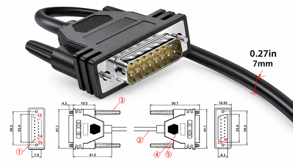
An accurate DB15 cable quotation starts by identifying the exact 15-position D-Sub connector rather than relying on the term “DB15” alone. Confirm the contact layout, connector gender, part number when available, termination method, backshell, locking hardware, cable exit direction and mating interface. These details influence compatibility, sourcing, assembly method and ultimately the price that can be quoted with confidence.
Connector Format
The first check is whether the project actually uses a standard-density 15-position D-Sub or a high-density 15-position D-Sub. The commercial term “DB15” is often used loosely, especially when a cable has been in service for years and purchasing staff only know that the connector contains fifteen contacts. That description is not always precise enough for sourcing because different 15-position D-Sub layouts use different physical contact arrangements and therefore different mating connectors.
In a replacement project, a useful first step is to photograph the mating face straight on so that the contact rows are visible. A manufacturer part number is even better because it can identify information that photographs do not show clearly, such as termination type, contact finish, screw-lock configuration and shell construction. When the exact part number is unavailable, the mating equipment connector, equipment drawing or a physical reference cable can provide additional evidence.
An experienced supplier should not convert an unclear “15-pin D-Sub” description into a firm component selection without reviewing that evidence. A connector mismatch can make every other detail in the cable specification irrelevant because a cable that cannot mate with the equipment is unusable regardless of how accurately the conductors were manufactured.
| Identification Item | Information to Provide | Practical Value |
| Contact count | 15 positions | Confirms the basic connector family |
| Contact layout | Standard density or high density | Prevents incorrect connector selection |
| Number of rows | Confirm from drawing or photo | Helps identify actual 15-position format |
| Connector part number | Manufacturer P/N if available | Reduces sourcing ambiguity |
| Mating connector | Equipment-side P/N or clear photo | Helps verify compatibility |
| Reference sample | Existing functional assembly | Useful when documentation is incomplete |
Gender and Mating
Every connector end should be identified independently as male or female because the term “DB15 cable” does not define the gender combination. A male-to-female extension cable uses a different BOM from a male-to-male or female-to-female assembly, and a DB15-to-terminal, DB15-to-another-D-Sub or DB15-to-custom-connector assembly introduces additional sourcing and mechanical requirements.
One common mistake occurs when someone photographs the equipment port rather than the cable connector and then reports the gender shown in the photo. The actual cable needs the mating configuration. For this reason, the RFQ should state something like “Side A: 15-position male cable connector, mating with attached equipment receptacle” instead of relying on a single word such as “male.”
The mating interface is equally important when a project is replacing an obsolete cable. If the equipment-side connector is accessible, providing its photograph or part number gives the manufacturer another way to verify the cable-side requirement. This extra confirmation takes little effort compared with the time lost when a sample arrives with the correct pin count but the wrong gender or contact arrangement.
Backshell and Locking
The backshell should not be treated as a decorative accessory. It protects the termination area, supports strain relief, influences shielding treatment and determines how much space the connector occupies behind the equipment interface. Projects may use assembled plastic hoods, metal backshells, metallized structures or molded connector ends depending on mechanical, electrical and appearance requirements.
Locking hardware also matters. Thumb screws, screw locks, jack screws and other retention arrangements need to match the mating equipment. A connector with the correct contact layout can still fail an installation check if the retention hardware does not engage correctly. When replacing an existing cable, close-up photographs of the top, side, mating face and cable entry can reveal details that are easy to miss in a general product photograph.
For custom molded connector ends, the backshell decision may extend into tooling. Overmolding can create a controlled strain-relief geometry and consistent appearance, but it may require tooling review, material selection and sample approval. An assembled standard hood generally follows a different manufacturing route. Defining the desired structure before quotation allows the supplier to price the correct process rather than treating all DB15 connector ends as equivalent.
Cable Exit and Fit
Cable exit direction becomes especially important in control cabinets, test equipment, industrial machinery and other installations with limited clearance. A straight backshell may be perfectly acceptable on an open workbench but interfere with a cabinet door or adjacent connector once installed. An angled exit may improve routing but changes the mechanical structure and can affect component choice.
Descriptions such as “left exit” or “right exit” should always include a reference view because direction changes depending on how the connector is held. A better approach is to mark the direction on a drawing viewed from the mating face or to photograph the connector installed in the equipment. If space is tight, include the available clearance behind and beside the connector.
These mechanical details are inexpensive to communicate but expensive to discover late. A dimensional sketch, equipment photograph and reference sample can prevent a sample from being electrically correct but physically impossible to install.
| Mechanical Detail | Strong RFQ Definition | High-Risk Definition |
| Connector format | Exact P/N or clear contact-layout photo | “15-pin connector” |
| Gender | Side A and Side B defined | Assumed from equipment photo |
| Backshell | Type/material/reference sample | “Standard shell” |
| Locking | Hardware or mating reference | Not mentioned |
| Exit direction | Drawing with reference view | “Left” or “right” only |
| Clearance | Dimensional sketch or installed photo | Checked after sampling |
Which Pinout and Wiring Details Are Required?
A DB15 connector provides fifteen possible contact positions, but it does not define the electrical circuit. The RFQ should therefore state how every used position connects to the opposite end, which contacts are intentionally unused, what conductor functions are involved and how the shield is terminated. The wiring definition should be clear enough that the finished cable can be assembled and tested without relying on assumptions.

Pin-to-Pin Map
A pin-to-pin map is one of the most useful documents in a DB15 cable RFQ because it converts an external connector description into an actual electrical assembly. A straight-through cable may connect pin 1 to pin 1, pin 2 to pin 2 and continue in sequence, while a custom equipment cable may cross several signals, group grounds or leave some contacts unused. Those two products can look identical from the outside.
The pinout can be provided as a drawing, schematic or simple table. Each used position should have a defined destination, and each intentionally unused position should be marked clearly. If conductor colors or identification numbers are already controlled by the design, they should appear in the same document. If colors can be selected by the manufacturer, that should be stated so the production team does not confuse an optional color choice with a functional requirement.
For repeat production, the pinout should eventually become part of the controlled manufacturing specification. Cablivo’s engineering fact library specifically includes wire-sequence confirmation and pinout review among the information that can be reviewed before quotation, sampling and mass production.
| Side A Pin | Side B Connection | Function | Shield Relation | Status |
| 1 | Per approved drawing | Signal / power / other | Project-defined | Connected |
| 2 | Per approved drawing | Signal / power / other | Project-defined | Connected |
| 3 | Per approved drawing | Ground if applicable | Confirm separately | Connected |
| 4 | NC if unused | — | — | Open |
| 5–15 | Define individually | Project-specific | Project-specific | Connected / NC |
The values above illustrate the information format rather than a universal DB15 pinout. Actual assignments must come from the equipment or system design.
Signal, Power and Ground
Pin numbers alone describe routing, but conductor functions provide engineering context. Identifying which contacts carry signals, power or ground can help determine whether all conductors should use the same AWG, whether shielding is necessary and whether certain conductors need different construction. A 15-position connector does not automatically imply fifteen identical signal wires.
For example, a control-system cable may use several conductors for low-level signals while other pins carry power or common ground. That arrangement can influence conductor selection and test requirements. The cable manufacturer should not redesign the customer’s electrical architecture from incomplete information, but the functional description helps the engineering team notice contradictions before materials are purchased.
When a full schematic is confidential, a simplified table can still be useful. Descriptions such as “signal,” “power,” “ground,” “reserved” or “unused” provide enough context for preliminary review without exposing every detail of the end equipment. Where confidentiality matters, project-document handling or NDA requirements can be discussed before sensitive drawings are shared.
Shield Termination
“Shielded cable” is not a complete specification because the shield still needs a defined electrical termination. The cable may use foil, braid or a combination, but the manufacturer must also know whether the shield connects to the connector shell, a drain wire, a specific ground contact or another point in the system.
One-ended and two-ended shield termination arrangements are not interchangeable. The correct choice depends on the customer’s electrical design and grounding strategy. For this reason, the manufacturer should not decide the shield termination by convention when the drawing is silent. If the project is still under engineering development, the requirement should be marked as open and reviewed before the sample is released.
Cablivo’s documented manufacturing system includes foil wrapping, braiding and shielded-cable processing, which allows shielded structures to be considered as part of a custom assembly rather than simply purchasing an unspecified cable. The final shield construction, however, should always follow the approved application requirement.
Testable Wiring Definition
A useful wiring specification should be written so that it can be turned into an inspection or test program. “Wire according to sample” may be enough for preliminary investigation, but it is weak as a long-term production instruction because it depends on human interpretation. Once the sample is understood, the wiring should be translated into controlled pin-to-pin criteria.
Each used contact should have an expected destination. Unused positions should be deliberately identified as open rather than simply omitted from the drawing. If multiple conductors share a common node, that relationship should also be documented. When the shell or shield must have electrical continuity to a defined point, include it in the test definition.
This becomes especially important when the project moves from a technician-built prototype into repeat production. The approved drawing and pinout give production and quality teams the same reference. Cablivo’s existing quality framework includes continuity and functional checking according to project requirements, providing a practical way to verify that finished assemblies match the approved wiring definition.
| Wiring Definition | Production Readiness | Main Risk |
| Complete pin-to-pin table | Strong | Low ambiguity |
| Electrical schematic with connector IDs | Strong after review | Pin numbering must be clear |
| Approved sample plus measured pinout | Strong after documentation | Requires reverse definition |
| Connector photos only | Insufficient | Internal wiring unknown |
| “Straight-through” without numbering | Weak | Numbering interpretation |
| “Same as old cable” only | Weak | No controlled test reference |
What Cable Construction Must Be Specified?
An accurate DB15 quotation requires a cable specification as well as the connectors. At minimum, define cable length, measurement method, conductor count, AWG, shielding and jacket requirements. If installation is mechanically demanding, also provide cable OD, flexibility needs and environmental conditions. The same DB15 connectors can be assembled to very different cables depending on the application.

Length and AWG
Cable length should be defined more carefully than a simple statement such as “2 meters.” Two teams may measure the same assembly differently. One may measure the exposed cable between backshells, while another uses connector-face-to-connector-face length. Those methods can create a meaningful difference in a cable that must fit a fixed routing path.
A drawing should therefore identify the measurement points and tolerance. If the assembly contains branches, pigtails or exposed leads, dimension each separately. When length is critical to equipment routing, note that clearly. When a wider manufacturing tolerance is acceptable, defining it in advance makes inspection criteria more realistic.
AWG and conductor count should also be confirmed rather than inferred from the connector. A 15-position connector does not necessarily use fifteen cores, and the conductors do not necessarily have the same gauge. Some contacts may be unused, while power and signal circuits may have different needs. Cable length and AWG are among the project fields Cablivo reviews when drawings or preliminary specifications are available.
| Cable Parameter | Information to Submit | Quotation / Engineering Value |
| Overall length | Numeric value and unit | Material consumption and fit |
| Measurement points | Face-to-face, shell-to-shell, etc. | Prevents interpretation differences |
| Length tolerance | Project-defined | Establishes inspection limits |
| Conductor count | Actual required cores | Defines cable construction |
| AWG | Per conductor or group | Supports electrical review |
| Spare conductors | Quantity if required | Changes cable structure |
| Cable OD | Nominal or maximum if critical | Must fit backshell and routing path |
Shield and Jacket
Shielding should be chosen according to the electrical environment rather than added automatically because the cable is used in industrial equipment. Some DB15 assemblies operate successfully without a shield, while others may require foil, braid or a combined structure because of nearby motors, drives, switching devices or sensitive signals.
The jacket should be selected with the same application-based logic. Materials such as PVC, TPE, TPU, PUR, silicone, PE and related compounds can provide different handling characteristics, but a material name alone does not define the actual requirement. The engineering discussion should start with flexibility, abrasion, environmental exposure, target market and any defined temperature or chemical conditions.
Cablivo’s fact library supports these material families while deliberately avoiding unsupported universal claims about temperature range, flame rating, abrasion cycles or regulatory compliance. This distinction is useful for procurement because a supplier should confirm actual material documentation rather than attach a high-performance label to every cable automatically.
Flexibility and OD
Cable flexibility and outer diameter often become visible only after the first installation attempt, which is why they should be considered earlier. A cable can be electrically correct and still be unusable if it is too stiff for the routing path, too large for the backshell entry or unable to bend within the available enclosure space.
Instead of writing only “flexible cable required,” describe how the product moves. A static cable inside a control cabinet has different demands from a cable that is repositioned each day. A cable that moves repeatedly with equipment introduces another level of mechanical review. This information helps determine whether standard construction is suitable or whether additional flexibility and validation should be discussed.
Outer diameter is also relevant to connector-end processing. A backshell clamp, strain relief or molded connector body must physically fit the selected cable. Cablivo’s manufacturing scope includes cable preparation, connector assembly, injection molding and overmolding, allowing the relationship between the cable OD and connector-end structure to be evaluated before a sample is produced.
Application Environment
The manufacturer should know where the cable will operate because DB15 assemblies appear in a wide variety of equipment. A laboratory instrument, automation controller, legacy machine interface, test fixture and industrial cabinet may all use similar connectors while imposing very different mechanical and environmental requirements.
Useful information includes whether the cable is static or moving, whether vibration is present, whether the route runs near high-noise electrical equipment and whether the product sees changing temperature or humidity. If oil, chemicals, outdoor exposure or corrosion risks are relevant, state the actual conditions rather than simply describing the product as “industrial.”
This application information also guides testing. Cablivo’s equipment base can support project-specific discussions involving electrical checks, pull-force evaluation, bending or swing testing, connector-life testing, salt spray and controlled temperature/humidity testing, but the fact library correctly avoids treating every test as mandatory for every assembly.
| Application Condition | Specification to Review | Main Reason |
| Static cabinet installation | OD, routing and connector clearance | Physical fit |
| Signal-sensitive equipment | Shield structure and termination | EMI control |
| Repeated cable movement | Flexibility and bending validation | Durability |
| High vibration | Locking and strain relief | Connection stability |
| Restricted enclosure | Cable exit and bend space | Installation |
| Environmental exposure | Jacket/material/test requirements | Application suitability |
| Export project | Documentation and target-market requirements | Compliance planning |
Which Requirements Affect DB15 Pricing?
DB15 cable pricing is determined by the complete product and manufacturing scope rather than the connector name alone. Connector source, cable structure, shielding, backshell, overmolding, tooling, testing, quantity, labels, packaging and material availability can all change the quotation. To compare suppliers fairly, every supplier should be pricing essentially the same specification rather than making different assumptions about missing details.

Components and Tooling
Connector selection is one of the most obvious cost variables, but the difference is not simply “cheap connector versus expensive connector.” A project that specifies an exact branded part number creates a different sourcing situation from a project that permits a technically reviewed equivalent. Contact finish, termination type, locking hardware, backshell and accessory choices can also change the component cost.
Molded connector ends add another variable because they may require tooling review, mold manufacture or modification, material preparation and sample confirmation. When existing tooling can meet the project requirement, the development path may be simpler. When a unique connector profile, logo position, exit direction or strain-relief geometry is required, additional tooling work may be necessary.
For quotation purposes, mandatory requirements should be separated from preferences. If a named connector part number cannot be substituted, state that clearly. If equivalent options can be considered, specify the mechanical, electrical and application requirements that must be preserved. This allows the supplier to explore sourcing options without quietly changing the approved specification.
Testing Scope
Testing affects price because every requirement consumes equipment time, operator time, fixtures or engineering preparation. For many cable assemblies, the most fundamental requirement is checking that the finished wiring matches the approved pinout and that there are no unintended open or short circuits. More demanding projects may add insulation, Hi-Pot, pull-force, bending, connector-life or environmental evaluation.
The quotation should distinguish between a production test and a qualification test. A continuity test may be required on routine production, while a bending or environmental validation may be performed only on defined samples or lots. Without that distinction, two suppliers can quote different inspection scopes while both believe they have answered the same inquiry.
Cablivo’s documented testing capability includes continuity, Hi-Pot/insulation, pull-force, bending/swing, connector-life and environmental testing equipment. The actual limits and frequencies, however, should come from the project requirement rather than being invented because the product happens to use a DB15 connector.
| Test Requirement | Information Needed Before Quote | Main Cost Driver |
| Pinout / continuity | Circuits to verify | Test program and cycle time |
| Open/short check | Production test requirement | Inspection scope |
| Hi-Pot / insulation | Voltage and acceptance criteria | Equipment and test time |
| Pull force | Termination and required value | Sample/test frequency |
| Bending | Cycle method and bend condition | Test duration |
| Connector life | Mating-cycle requirement | Validation duration |
| Environmental test | Temperature/humidity/corrosion criteria | Chamber and test time |
Quantity and Packaging
Quantity changes the economics of component sourcing, machine setup, tooling and production preparation. A prototype requirement, an initial production order and an annual supply program represent different commercial situations even when the drawing is identical.
For many Cablivo custom cable projects, the documented MOQ starts from 500 pieces, while the final MOQ depends on connector type, cable structure, materials, overmolding, tooling, packaging and order quantity. Providing an expected first-order quantity therefore gives the quotation a realistic commercial basis.
Packaging should also be defined early. Bulk packing, individual bags, barcode labels, serialized labels, SKU stickers, carton marks and retail packaging use different materials and labor. When the assembly is part of a multi-SKU equipment program, label accuracy can be just as important as cable construction because a technically correct cable with the wrong SKU label can still create a receiving or assembly problem.
Availability and Lead Time
Connector availability can influence both price and schedule, especially when an exact part number is specified. A quotation based on a component that is difficult to obtain may look attractive until purchasing begins. For that reason, connector availability should be reviewed rather than assumed.
The RFQ should state whether substitutions are prohibited, acceptable after approval or already qualified. Where equivalent components may be considered, the manufacturer still needs to compare mating geometry, gender, termination, locking hardware, contact arrangement and any material or performance requirements.
Lead time also depends on more than assembly labor. The Cablivo fact library specifically identifies product structure, material availability, connector sourcing, tooling, quantity, testing and packaging as factors that can affect sample or production timing, and it avoids making one fixed lead-time promise for every project.
| Quote Variable | Lower Complexity | Additional Review Needed |
| Connector | Defined and available part | Restricted source or uncertain supply |
| Cable | Existing standard structure | Custom material/construction |
| Shield | Simple defined structure | Complex or custom termination |
| End treatment | Standard backshell | Custom overmold/tooling |
| Wiring | Simple approved pinout | Crossovers or mixed functions |
| Testing | Standard electrical check | Special mechanical/environmental tests |
| Packaging | Bulk packing | Custom labels or multi-SKU packaging |
| Quantity | Confirmed production quantity | Unclear or changing volume |
How Can You Get a Quote Without Complete Drawings?
A complete drawing is the best reference for repeat manufacturing, but you can begin a DB15 cable quotation without one. Clear connector photos, an existing sample, approximate cable length, application, target quantity and any available BOM or schematic can support a preliminary review. The first engineering task is to identify which missing details must be confirmed before a firm quote or production-ready sample is released.

Photos and Samples
Photographs are useful when they answer specific technical questions. A single distant photograph rarely does that. A better photo set includes the entire cable, straight-on views of both connector mating faces, side views of the backshells, cable-entry areas, labels and any unusual branches or mechanical details. A photograph of the equipment-side mating connector can provide additional confirmation.
A physical reference sample provides even more information because dimensions, connector fit, cable OD and handling characteristics can be examined directly. When authorized, the sample may also support continuity mapping of an undocumented pinout. The objective should not be to manufacture indefinitely from the instruction “same as sample.” The useful outcome is to convert the confirmed sample information into a controlled drawing, pinout and BOM.
Cablivo’s documented inquiry workflow explicitly allows projects without complete drawings to start with sample photos, connector photographs, cable length, application details and target quantity. That makes it possible to begin the technical conversation while still identifying the information required for a final quotation.
| Available Information | Can Preliminary Review Start? | What Still Needs Confirmation? |
| Drawing + BOM + pinout | Yes | Commercial/project details |
| Drawing + pinout | Yes | Material sourcing details |
| Physical working sample | Yes | Controlled drawing/BOM/pinout |
| Detailed photos | Yes, preliminary | Internal wiring and exact materials |
| Connector P/N + length | Limited | Pinout, cable construction and tests |
| “Need DB15 cable” only | Not enough | Most technical information |
BOM and Partial Data
A BOM can give engineering and purchasing teams a common component reference. It may identify connector manufacturers and part numbers, backshells, wire specifications, terminals, heat-shrink components, labels and packaging materials. It is especially valuable when connector sourcing or approved-component control matters.
The BOM does not replace the drawing because it explains what parts are used but not how they are assembled. Likewise, a schematic may define the electrical logic while leaving cable length, backshell geometry and packaging undefined. A physical sample may show construction but not the approved material source. These different records become more useful when reviewed together.
Cablivo’s documented BOM review process can cover connector models, terminals, wire specifications, materials, labels, packaging items and potential sourcing risks before quotation or sampling. For an older project, combining a partial BOM with a reference sample and equipment information is often much more reliable than asking a supplier to identify the entire cable from a photograph alone.
What Must Be Frozen
Incomplete information is acceptable during the first technical discussion, but it should not remain unresolved indefinitely. Before a useful sample can be made, the connector family, gender, pinout, cable length and critical cable construction should be sufficiently defined for the sample to perform its intended function.
Before mass production, the final drawing, approved pinout, BOM, sample reference, labeling requirements, packaging files and test criteria should agree with one another. Revision control becomes important at this stage. A correctly manufactured cable built to an obsolete drawing is still the wrong product.
The engineering review is therefore not simply a document-collection exercise. It should identify conflicts and close open points before they become production assumptions. Cablivo’s documented engineering capabilities include drawing review, BOM review, connector confirmation, pinout review, material selection, prototype development and sample revision before production preparation.
RFQ Package
A practical DB15 RFQ does not need to resemble a large technical dossier. It simply needs enough controlled information that two capable manufacturers would understand essentially the same cable.
For a well-documented project, send the drawing, pinout and BOM together with target quantity, application, testing and packaging requirements. For a replacement project without drawings, begin with the physical sample, connector photographs, approximate cable dimensions, application and quantity. Unknown fields can be marked as “TBC” rather than left to supplier assumptions.
That approach also makes quotations easier to compare. If one supplier is pricing a branded connector, metal backshell and individual packaging while another assumes an equivalent connector, plastic hood and bulk packing, the two prices are not answering the same question.
| Final RFQ Item | Preferred Information | Project Value |
| Connector A | Type, gender, P/N and backshell | Component identification |
| Connector B | Type, gender, P/N or termination | Defines full assembly |
| Pinout | Complete pin-to-pin map | Assembly and testing |
| Cable length | Dimension and measurement reference | Fit and material control |
| Wire specification | AWG, conductor count, construction | Electrical/mechanical review |
| Shielding | Structure and termination | EMI and assembly definition |
| Drawing | Dimensions and revision | Manufacturing control |
| BOM | Components and revision | Sourcing control |
| Quantity | Sample and production demand | Quotation basis |
| Application | Equipment and environment | Engineering context |
| Testing | Required tests and acceptance criteria | Quality planning |
| Labels | Artwork, data and placement | Production accuracy |
| Packaging | Bulk, individual or custom | Cost and shipment preparation |
| Destination | Country or shipping location | Export planning |
| Reference sample | If available | Reverse-definition support |
A project does not need every field to be perfect before the first conversation. It does need a clear route from uncertain information to confirmed specifications. Cablivo’s project intake is built around drawings, reference samples, BOMs, connector models, cable length, AWG, pinout, application, target quantity, testing, packaging and shipping information because those fields reduce quotation assumptions and create a clearer path from engineering review to sample confirmation and repeat production.
If you already have a DB15 drawing, pinout and BOM, those documents are the best place to start an RFQ. If your project is an older equipment cable with no complete drawing, send clear sample photographs, connector close-ups, cable length, application and target quantity first. The missing details can then be identified systematically before sampling or final pricing.
Cablivo is the overseas-facing website brand of Shenzhen Tianxiaowei Electronics Co., Ltd., a Shenzhen-based custom cable, wire harness and cable assembly manufacturer with 18 years of industry experience, more than 20,000 square meters of factory space, a 1,500+ person team and three manufacturing bases. Its documented project support covers drawing review, sample development, cable manufacturing, testing, packaging, labeling and shipment coordination.
For a DB15 cable assembly quotation, send the information you already have rather than delaying the project while trying to create a perfect document package. A drawing, pinout, BOM, connector model, cable length, AWG, sample photos, target quantity, testing requirements and packaging plan provide a strong starting point. When some of those items are still unknown, the first engineering review can focus on identifying the gaps that affect connector selection, cost, manufacturability and sample validation before the project moves into repeat production.