Skip to content


What Information Is Needed to Quote DB9 Cable Assembly Accurately?
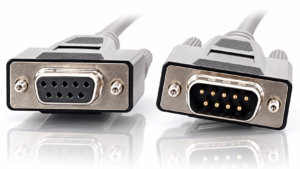
A DB9 cable assembly may look simple from the outside, but a reliable quotation depends on far more than connector gender and cable length. Two assemblies with nearly identical black jackets and 9-pin connectors can use different contact systems, pin mappings, shield structures, conductor gauges, backshells, locking hardware, strain relief, tests, and packaging. When those details are missing, two suppliers can return different prices while technically quoting two different products.
To quote a DB9 cable assembly accurately, provide the connector configuration at both ends, pin-to-pin wiring, cable length and construction, conductor and shielding requirements, application conditions, testing criteria, target quantity, packaging needs, and any available drawing, BOM, sample, or connector part numbers. These details allow the manufacturer to evaluate the same product you actually intend to purchase.
This is especially important when procurement compares several factories. Imagine three suppliers receiving an RFQ that only says “DB9 male to female, 2 meters.” One assumes straight-through wiring, another selects a shielded RS-232-style construction, and the third uses an unshielded general-purpose cable. All three prices may look reasonable, but the comparison is already invalid. A quote becomes useful only when engineering, procurement, and manufacturing are working from the same product definition.
What DB9 Connector Details Should You Specify?
For an accurate DB9 cable assembly quote, specify the connector gender at both ends, exact connector or approved part number where available, termination style, backshell type, cable-exit direction, locking hardware, and any dimensional restrictions. These details influence component sourcing, assembly process, installation fit, shielding continuity, tooling needs, and the final mechanical construction of the cable.
Connector Configuration
Start by defining End A and End B separately. “DB9 male to female” is useful, but it still leaves several engineering decisions unresolved. A 9-position D-Sub family can include male and female interfaces, different contact systems, termination methods, shell constructions, plating specifications, fastening hardware, and backshell options. For an equipment-specific project, those differences can determine whether a finished cable actually mates correctly with the target device.
If the project replaces an existing cable, include the connector manufacturer and part number when they are visible on the original product or listed in an approved BOM. If those numbers are unavailable, provide clear close-up photos of the connector face, rear shell, locking hardware, cable exit, and mating equipment. A reference sample is even more useful because dimensions, hardware, connector fit, and internal construction can be checked together rather than estimated from photographs.
Backshell and Cable Exit
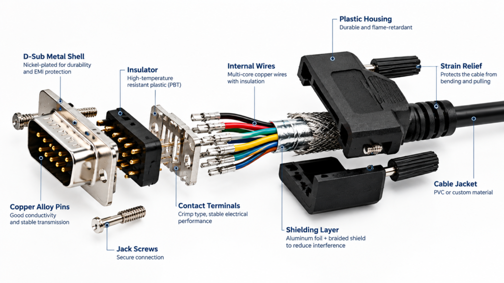
The backshell should be treated as part of the functional design rather than as a decorative cover. It protects the wire termination area, supports strain management, influences cable routing, and can form part of the shielding path when a metal construction is used. A plastic hood may be perfectly suitable for one indoor equipment connection, while another project may require a metal shell, custom molded body, or a more compact mechanical profile.
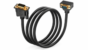
Installation space often makes cable-exit direction important. A straight exit can work well on test equipment sitting on a bench but may conflict with a control-cabinet door, adjacent connector, or enclosure wall. An angled exit can reduce routing pressure, but the direction must match the real installation. Cable outer diameter also needs to fit the selected backshell or strain-relief system. Where space is restricted, providing a drawing or maximum envelope dimension before quotation can prevent a mechanically correct connector from becoming an unusable finished assembly.
| Connector RFQ Item | Typical Options | What to Confirm | Selection Value |
| End A | Male / Female | Mating interface | Prevents gender mismatch |
| End B | Male / Female / Other connector | Equipment requirement | Defines full assembly |
| Connector P/N | Customer-controlled or manufacturer-proposed | Substitution rules | Improves quote comparability |
| Backshell | Plastic / Metal / Molded | Protection and shielding needs | Defines mechanical structure |
| Cable Exit | Straight / Angled / Custom | Installation clearance | Reduces routing interference |
| Hardware | Jackscrews / Thumbscrews / Other | Mating thread and panel design | Prevents installation problems |
| Termination | Crimp / IDC / Solder-based construction | Connector family and process | Affects tooling and labor |
| Cable OD | Project-specific | Backshell and routing limits | Prevents fit problems |
| Overmold | None / Standard / Custom | Shape and strain relief | Clarifies tooling scope |
Termination and Hardware
Different D-Sub connector families can use different wire termination systems, so the assembly method should not be assumed from the external connector shape. Crimp contacts, IDC constructions, and solder-related designs all exist in the wider D-Sub ecosystem. Each method creates a different production route, equipment requirement, inspection method, and cost structure. If the customer already has an approved connector and contact combination, that component definition should stay inside the RFQ.
For a new product, the manufacturer can help review the available options, but the final quotation should be based on a defined process rather than a temporary assumption. Production quantity also matters. A method that is practical for a development sample may not be the most efficient choice for a repeat program involving thousands of identical terminations. The goal is not to choose the most complicated process, but to select one that can be manufactured, inspected, and reproduced consistently after sample approval.
Standard Hood or Custom Overmold
A standard backshell is usually appropriate when the project can accept an existing mechanical design. Custom overmolding becomes more relevant when the cable needs controlled strain relief, improved connector protection, a specific outer shape, limited installation dimensions, consistent appearance, or a project-specific cable-exit profile. This distinction affects quotation because custom molding can introduce tooling evaluation, material selection, dimensional confirmation, prototype work, sample modification, and production controls.
For molded DB9 assemblies, provide the desired shape, reference sample, drawing, cable exit, connector type, cable OD, appearance requirement, and any space restrictions. Cablivo’s documented custom cable workflow includes connector confirmation, overmold structure review, tooling discussion, prototype development, and sample revision, which allows these mechanical details to be reviewed before the approved sample moves into production
Which Pinout and Electrical Details Are Needed?
An accurate DB9 cable RFQ needs a pin-to-pin wiring map, populated and unused positions, relevant signal functions, shield and ground termination, and any straight-through, crossover, null-modem, or proprietary wiring requirements. The connector shape does not define the circuit. The approved pinout should therefore control quotation, prototype wiring, electrical testing, and later production inspection.
Pin-to-Pin Mapping
The pinout is often the most important electrical document in the entire project. A manufacturer can immediately identify a 9-position connector, but the connector does not reveal whether Pin 2 connects to Pin 2, Pin 3, or another contact at the opposite end. The safest format is a simple table that identifies each populated position on End A and its destination on End B, while also identifying unused contacts as not connected.
This becomes even more important when one end is not DB9. A DB9-to-terminal, DB9-to-wire harness, DB9-to-board connector, or DB9-to-proprietary interface should map every required contact or cavity clearly. For repeat programs, the pinout should have a revision number or be embedded in the controlled drawing. That avoids relying on old emails, screenshots, or engineering notes that may no longer match the approved production sample.
Signal Function
Adding signal names to the wiring table gives engineering teams useful context. Labels such as transmit, receive, ground, control, alarm, CAN, sensor signal, or customer-defined signal help explain the purpose of individual circuits and can reveal conflicts before a sample is assembled. Signal names do not replace the physical pin map, but they make it easier to evaluate conductor structure, shielding, grounding, and testing requirements.
It is also important not to assume that every DB9 assembly is automatically an RS-232 cable. The same physical connector format appears in industrial controls, test systems, legacy equipment, instrumentation, automation products, and proprietary device interfaces. The equipment manual or customer schematic should therefore remain the source of truth. When the application is confidential, a short description of signal type and equipment function is normally more useful than disclosing the full system design.
| Electrical RFQ Field | Useful Input | Acceptance Standard | Why It Matters |
| Pin Mapping | A1→B1, A2→B3, etc. | Every used circuit defined | Controls wiring |
| Unused Pins | Explicit “NC” positions | No unintended connection | Prevents assumptions |
| Wiring Type | Straight-through / Crossover / Proprietary | Match device requirement | Prevents functional mismatch |
| Signal Name | TX, RX, GND, Control, CAN, etc. | Equipment documentation | Supports engineering review |
| Shield Structure | None / Foil / Braid / Combined | Drawing or approved structure | Controls EMI design |
| Shield Termination | Shell / Pin / Drain / One end / Both ends | System requirement | Controls grounding behavior |
| Ground | Signal / Chassis relationship | Customer schematic | Prevents ground errors |
| Revision | Rev A / Rev B / Controlled document | Latest approved revision | Controls production version |
| Electrical Check | Continuity and pinout verification | Approved wiring map | Detects opens and miswires |
Shield and Ground Strategy
“Shielded cable” is not a complete specification because shielding involves both material structure and electrical termination. A cable may use foil shielding, braided shielding, or a combination of structures, but the shield still has to terminate somewhere. Depending on the equipment design, that termination could involve the connector shell, a drain wire, a defined contact, one end of the assembly, or both ends.
The manufacturer should not invent that grounding scheme simply to complete an RFQ. If electromagnetic interference is a real concern, provide the application context: nearby motors, drives, switching power equipment, cable routing, cable length, cabinet grounding, and any existing system requirement. This allows the physical cable structure to be reviewed in context. The correct shield design is not the one with the most layers; it is the one that matches the electrical environment and approved equipment architecture.
Verification Before Production
The pinout should continue to control the product after quotation. During sample development, continuity and circuit mapping can be verified against the approved wiring definition. Once the sample is accepted, the same controlled pinout should be reflected in production test fixtures, work instructions, inspection records, and SKU identification. This becomes especially important when several DB9 products share the same external appearance but contain different internal wiring.
The project fact library lists pinout review, wire-sequence confirmation, continuity testing, pinout checks, connector-fit checks, and related electrical inspection directions among Cablivo’s supported project activities. A controlled relationship between drawing, sample, test fixture, label, and packing information gives procurement teams far more useful evidence than a generic statement that every cable is simply “tested.”

Which Cable Specifications Affect the Quote?
The quote depends on much more than the two DB9 connectors. Finished length, conductor count, AWG, conductor stranding, shielding, cable OD, jacket material, flexibility, color, and environmental requirements can change material consumption, termination compatibility, processing difficulty, mechanical fit, testing, and packaging. Define the cable construction separately so every supplier is pricing the same internal design.
Length and Measurement
Cable length needs a measurement reference. “Two meters” may refer to the exposed cable between backshells, overall connector-tip-to-connector-tip length, or another dimension defined by the drawing. For equipment with limited routing space, this distinction matters. A cable that is only a few centimeters longer or shorter than intended can create installation problems even if every electrical circuit is correct.
When several length variants are needed, treat them as separate controlled SKUs rather than assuming packaging and identification will take care of the difference automatically. A 0.5-meter, 1-meter, 2-meter, and 5-meter version may share the same connectors and pinout, but they consume different material, occupy different package volumes, and create a real risk of SKU confusion during warehousing or field installation. Length tolerance should also be stated whenever it has installation significance.
Conductor Structure
Wire gauge should be selected from the electrical and mechanical requirements rather than from the connector name. A DB9 assembly carrying low-current serial signals can have different conductor needs from an equipment cable carrying control power, mixed signals, or customer-specific functions. Conductor count, AWG, strand construction, insulation, and electrical requirement should therefore be included whenever they are controlled by engineering.
If an approved bulk-cable part number already exists, sending that part number is usually stronger than trying to describe the structure from memory. For a new project, provide current, voltage, signal type, desired flexibility, maximum cable OD, environmental requirements, and termination constraints. Those inputs allow engineering to review a suitable construction without pretending that one generic “DB9 cable” specification works for every machine or communication system.
| Cable Parameter | Quote-Ready Input | Selection Question | Risk if Missing |
| Length | Dimension + measurement reference | How is finished length measured? | Different quote basis |
| Conductors | Exact conductor count | Are all positions used? | Wrong bulk cable |
| Wire Gauge | AWG or approved wire specification | What current and termination apply? | Electrical mismatch |
| Stranding | Defined by application | Fixed or flexible use? | Handling mismatch |
| Shielding | None / Foil / Braid / Combined | Is interference a concern? | EMI assumptions |
| Jacket | Approved material or requirement | What environment is expected? | Wrong durability |
| Cable OD | Actual or maximum permitted | Will it fit backshell and routing? | Assembly interference |
| Color | Standard or controlled color | SKU or brand requirement? | Identification errors |
| Flex Requirement | Fixed / Occasional / Repeated | How will cable move? | Premature damage |
| Bulk Cable P/N | Preferred when qualified | Is substitution allowed? | Non-equivalent materials |
Shielding and Cable OD
Shielding influences both electrical behavior and physical dimensions. Adding foil, braid, drain wire, fillers, or extra insulation can increase cable OD and change flexibility. That means cable construction and connector selection need to be reviewed together. A thicker shielded cable may no longer fit the selected backshell, strain-relief clamp, gland, enclosure opening, or molded transition.
If the equipment imposes a maximum cable diameter because the assembly passes through a narrow cabinet opening or tightly packed harness route, state that limit at RFQ stage. Doing so allows the manufacturer to compare conductor count, insulation thickness, shielding structure, jacket thickness, and backshell compatibility before producing samples. It is far more efficient to discover an OD conflict during drawing review than after a technically correct but mechanically oversized cable has already been shipped for validation.
Jacket and Flexibility
Jacket material should be selected around the real environment. A cable fixed permanently inside a clean control cabinet does not face the same mechanical conditions as one handled by service technicians every day. Likewise, an assembly exposed to oils, abrasion, humidity, outdoor conditions, elevated temperatures, or frequent bending may need a different structure from a protected indoor signal cable.
Flexibility should also be described in practical terms. “Soft cable” is subjective, while “fixed installation,” “occasional manual movement,” and “repeated movement during equipment operation” describe actual use. The uploaded fact library documents cable length, AWG, connector type, cable jacket, shielding, pinout, application requirements, and operating environment as relevant inputs for custom cable review. Those details provide a much stronger foundation for material selection and sample evaluation than appearance alone.

What Application and Testing Requirements Should You Provide?
Provide the equipment type, installation environment, movement conditions, electrical function, target market, expected failure risks, and required verification. Testing should follow the actual application rather than a universal checklist. At minimum, the agreed inspection plan should confirm the characteristics that define the approved assembly, particularly wiring, connector fit, workmanship, dimensions, labels, and any project-specific electrical or mechanical requirements.
Application Conditions
Application information explains the engineering reason behind many specifications. A shield, metal backshell, flexible jacket, right-angle cable exit, or custom strain relief may look unnecessary when viewed as isolated cost items. Once the manufacturer knows the cable is installed beside motor drives, routed through a narrow enclosure, moved during machine operation, or disconnected repeatedly during service, the requirement becomes easier to evaluate.
Useful application details include indoor or outdoor use, fixed or moving installation, cabinet or external routing, vibration, humidity, abrasion, chemical exposure, temperature conditions, and expected mating frequency. The customer does not need to reveal confidential equipment design. A description such as “fixed communication cable inside an industrial controller” or “service cable repeatedly connected to diagnostic equipment” is often enough to guide meaningful engineering questions without exposing sensitive project information.
Electrical Testing
Continuity and pinout verification are particularly important because a DB9 cable can look perfect while being electrically incorrect. The acceptance reference should be the controlled wiring map: required circuits must connect correctly, specified open circuits must remain open, and there should be no unintended connections where isolation checks are part of the test plan.
Additional electrical tests can be introduced when the project calls for them. Insulation or Hi-Pot testing, resistance measurement, signal-related checks, or customer-specific functional tests may be relevant, but their voltage, duration, limits, fixtures, and acceptance criteria should come from a defined project requirement. Test parameters should never be borrowed casually from an unrelated cable simply because the equipment is available on the production floor.
| Test / Inspection | Relevant When | Acceptance Basis | Information Needed |
| Continuity | Wired circuits must be verified | Approved pinout | Required circuits |
| Pinout Check | Wiring is custom | Controlled drawing | Pin-to-pin table |
| Short Check | Multiple circuits are closely terminated | Test plan | Isolation requirement |
| Connector Fit | Equipment mating is critical | Approved mating connector | Equipment or mating P/N |
| Visual Inspection | Workmanship matters | Approved sample | Cosmetic criteria |
| Dimensional Check | Installation space is controlled | Drawing tolerance | Critical dimensions |
| Pull-Force Test | Termination retention is important | Project specification | Force and method |
| Bend / Swing Test | Repeated movement occurs | Defined cycle requirement | Movement profile |
| Hi-Pot / Insulation | Electrical safety requires verification | Applicable specification | Voltage, time, limits |
| Label Check | SKU control is important | Approved label file | SKU and barcode |
| Packaging Check | Export or line-side delivery is controlled | Packing specification | Quantity and packing method |
Mechanical and Reliability Checks
Mechanical testing should be chosen around realistic failure modes. A crimped termination may require pull-force evaluation. A cable repeatedly handled by technicians may need more attention at the connector-to-cable transition. A moving assembly may require bending or swing testing, while exposed metal components in a harsh environment may require corrosion-related evaluation. Selecting tests in this way produces more useful evidence than performing a long list of unrelated checks.
The acceptance method also needs definition. “Pull test required” is incomplete without force and fixture details when the customer controls those parameters. “Bending test” can mean very different things depending on bend radius, angle, speed, load, number of cycles, and failure definition. A professional RFQ does not need to contain unnecessary laboratory complexity, but when a performance characteristic is critical, both parties should understand what passing actually means.
Compliance and Documentation
Compliance requirements should be discussed before materials and components are locked because they can affect sourcing, jacket selection, connector choice, declarations, inspection documents, and testing. A DB9 assembly should not automatically be presented as compliant with every possible standard simply because individual raw materials have separate certifications. The applicable requirement depends on the complete product, end use, customer specification, and target market.
The company fact library follows the same boundary and states that certification and testing requirements should be reviewed according to product type, target market, and project specification rather than claimed universally. For long-term supply programs, controlled drawings, approved samples, inspection criteria, label files, packaging documents, and revision history can become as important as the physical cable because they help maintain consistency across repeat orders.

How Do You Prepare a Complete DB9 Cable RFQ?
Build the RFQ around one controlled product definition: connectors, pinout, cable construction, length, application, testing, quantity, labeling, packaging, and supporting drawings or samples. Separate confirmed requirements from unresolved items. A quote-ready package lets different suppliers price the same assembly, reveals engineering gaps before sampling, and creates a cleaner path from quotation through sample approval to mass production.
Drawing and BOM
A drawing is valuable because it brings mechanical and electrical information into one controlled reference. For a DB9 cable, a practical drawing can show End A and End B, connector part numbers, cable length, backshell orientation, cable specification, pinout, labels, critical dimensions, tolerances, and revision history. A BOM provides additional control when specific connectors, contacts, bulk cable, hardware, heat-shrink items, or packaging components have already been approved.
The critical issue is consistency. The drawing, BOM, pinout, purchase order, sample, and label file should all describe the same revision of the product. If a connector changes after the first sample or a pin assignment changes during equipment testing, update the controlled documents before production. Relying on an email saying “please use the new version” creates unnecessary risk when the project is transferred from engineering into purchasing, production, quality inspection, and repeat ordering.
Starting Without a Drawing
A project can still begin when no formal drawing exists. An existing sample, detailed photographs, equipment documentation, connector markings, cable length, known pinout, application description, and target quantity can provide enough information for an initial engineering review. The important point is to identify which facts are confirmed and which still need verification rather than silently filling every missing field with a standard assumption.
Cablivo’s documented project boundary specifically allows customers without complete drawings to begin with sample photos, connector photos, cable length, application information, and target quantity so unresolved requirements can be identified before sampling. This approach is particularly useful when replacing discontinued cables, localizing an existing assembly, or developing a new equipment interface from a working prototype.
Quantity, SKU and Packaging
Quantity should represent the real commercial stage of the project. Prototype validation, first production, repeat orders, and long-term programs have different sourcing and production implications. If several volumes are being evaluated, include meaningful quantity breaks rather than asking for one theoretical volume that is unlikely to be ordered. Material sourcing, component availability, tooling economics, test fixtures, packaging, and production methods can all change as quantities increase.
For many custom cable projects, Cablivo’s documented MOQ begins at 500 pieces, while the final MOQ depends on connector type, cable construction, materials, overmolding, tooling, packaging, and order quantity. Packaging should also be defined early when the cables will enter a customer warehouse, assembly line, distributor channel, or retail program. SKU labels, barcodes, carton marks, wire-number labels, individual bags, bulk packing, kitting, and other requirements can materially affect order preparation.
| RFQ Category | Minimum Input | Stronger Production Input | Status |
| End A | Gender + connector type | Approved manufacturer P/N | Confirmed / Open |
| End B | Gender + connector type | Approved P/N + mating reference | Confirmed / Open |
| Wiring | Pin-to-pin map | Controlled pinout revision | Confirmed / Open |
| Cable | Length + basic construction | Qualified bulk-cable P/N | Confirmed / Open |
| AWG | Gauge or electrical requirement | Approved conductor specification | Confirmed / Open |
| Shield | Required / Not required | Structure + termination drawing | Confirmed / Open |
| Mechanical | Backshell + exit direction | Critical dimensions | Confirmed / Open |
| Application | Equipment/use description | Environmental conditions | Confirmed / Open |
| Testing | Functional checks | Test method + acceptance limits | Confirmed / Open |
| Quantity | Target volume | Sample + initial + repeat forecast | Confirmed / Open |
| Labels | Basic identification | Approved SKU/barcode artwork | Confirmed / Open |
| Packaging | Bulk / Individual | Full packing specification | Confirmed / Open |
| Documentation | Photos / Sample | Drawing + BOM + revision | Confirmed / Open |
| Destination | Country / Region | Delivery and channel requirements | Confirmed / Open |
| Timing | Target project timing | Sample and production milestone plan | Confirmed / Open |
RFQ to Mass Production
A good RFQ should become the starting point for the entire project rather than disappearing after a price is issued. The most reliable sequence is requirement review, drawing or sample review, BOM and connector confirmation, quotation, sample development, sample testing, customer approval, production preparation, functional inspection, labeling, packaging, and shipment coordination. The uploaded project fact library records the same workflow for custom cable programs.
The approved sample plays an important role because it allows the customer to confirm connector mating, cable feel, wiring, dimensions, appearance, labels, and practical installation before a larger order begins. Any sample revision should then be reflected in the final drawing, BOM, pinout, or specification. This reduces the risk of a sample being correct while mass production follows an older document revision.
For a DB9 cable assembly inquiry, the most useful starting package includes whatever information is already available: drawing, BOM, reference sample or photographs, connector model, pinout, cable length, AWG, application, target quantity, testing requirements, labeling, and packaging. These project inputs are consistent with Cablivo’s documented custom cable review process.
The purpose of an accurate RFQ is not to make purchasing unnecessarily complicated. It is to remove the hidden assumptions that make supplier quotations difficult to compare. Once connector construction, wiring, cable structure, application, testing, volume, and packaging are aligned, engineering and procurement teams can evaluate suppliers against the same product definition rather than comparing prices for assemblies that only look similar on the surface.
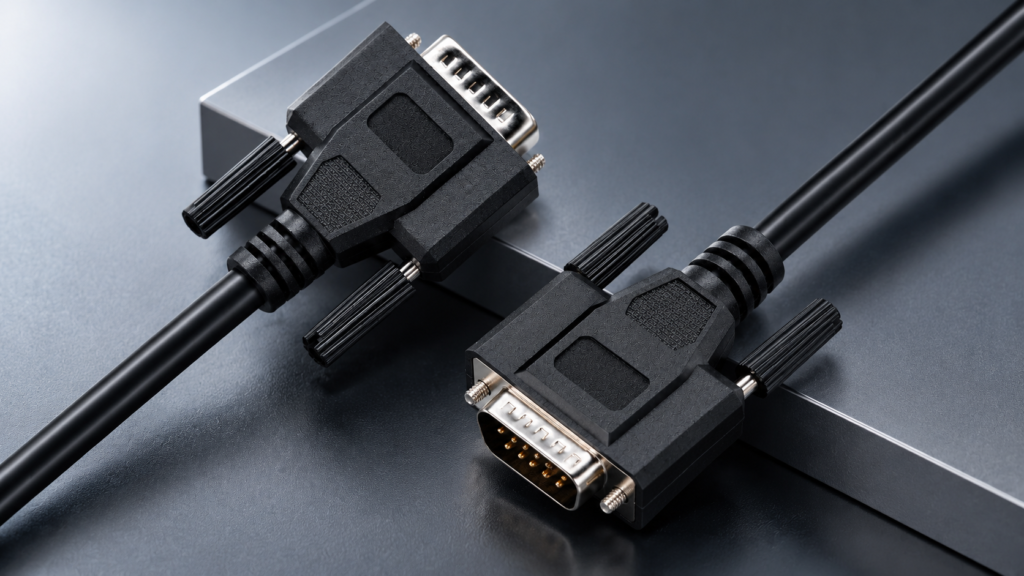
For teams preparing a custom DB9 cable assembly, the most effective first step is not to wait until every specification is perfect. Send the information that is already confirmed and make the unresolved items visible. A drawing, pinout, sample photo, BOM, connector model, cable length, AWG, application, target quantity, testing requirement, label file, or packaging plan gives the manufacturer something concrete to review and creates a much stronger starting point than a short description such as “DB9 cable, please quote.”
Cablivo supports custom cable projects through requirement review, connector and pinout confirmation, sample development, production preparation, testing, packaging, labeling, and shipment coordination rather than treating quotation as an isolated price exercise. The objective is to make sure that the assembly being priced is the same assembly that will later be sampled, tested, approved, packed, and reproduced in mass production.
If you are developing or sourcing a custom DB9 cable assembly, send your available drawing, pinout, BOM, sample photos, connector information, application details, target quantity, and packaging requirements to Cablivo for project review and quotation. A well-defined RFQ gives both engineering and procurement teams a clearer basis for evaluating cost, sample feasibility, manufacturing risk, testing scope, and long-term supply before the project moves forward.