 跳到内容
跳到内容 
Cable In-Process Inspection
Production-stage inspection for custom cables, wire harnesses and cable assemblies manufactured from approved samples, drawings and project files.
Cablivo places inspection points inside the manufacturing flow rather than relying only on finished-product checks. Production requirements can be reviewed against approved samples, final drawings, BOM revisions, connector specifications, pinout files, labels and packaging instructions.
- First-piece confirmation before production release
- IPQC checks across critical manufacturing stages
- Project-specific dimensional, assembly and connection checks
- Inspection records supporting batch review and repeat production
- Quality coordination from incoming materials to outgoing inspection
What Cable In-Process Inspection Means During Production
In-process inspection examines defined characteristics while cable manufacturing is still underway. Early checks help identify deviations before additional assembly, overmolding, labeling or packaging increases the affected quantity and correction cost.
Inspection Before Production Deviations Spread
Cable in-process inspection, often managed through IPQC activities, takes place between production release and finished-product inspection. The purpose is not to repeat a final inspection at every workstation. Inspection points are selected around operations where an error may affect function, fit, appearance, assembly or repeat-order consistency.
For a custom cable assembly, one early deviation can influence many downstream operations. An incorrect cutting length may create installation problems after connectors are fitted. A wrong pinout may remain hidden until electrical verification. A terminal inserted into the wrong housing position may require extensive rework after bundling or sleeving. An incorrect overmolding direction may become difficult to correct after the molded structure is complete.
A well-defined inspection flow compares production output with agreed references. References may include:
- Approved cable samples
- Final drawings
- Final BOM revisions
- Connector datasheets
- Pinout or wiring diagrams
- Work instructions
- Label files
- Packaging versions
- Agreed inspection requirements
The inspection scope depends on cable type and process risk. A molded connector cable, an industrial wire harness and an extruded custom cable do not require identical checkpoints. Cable structure, materials, connection method, quantity, application and packaging program influence the final inspection plan.
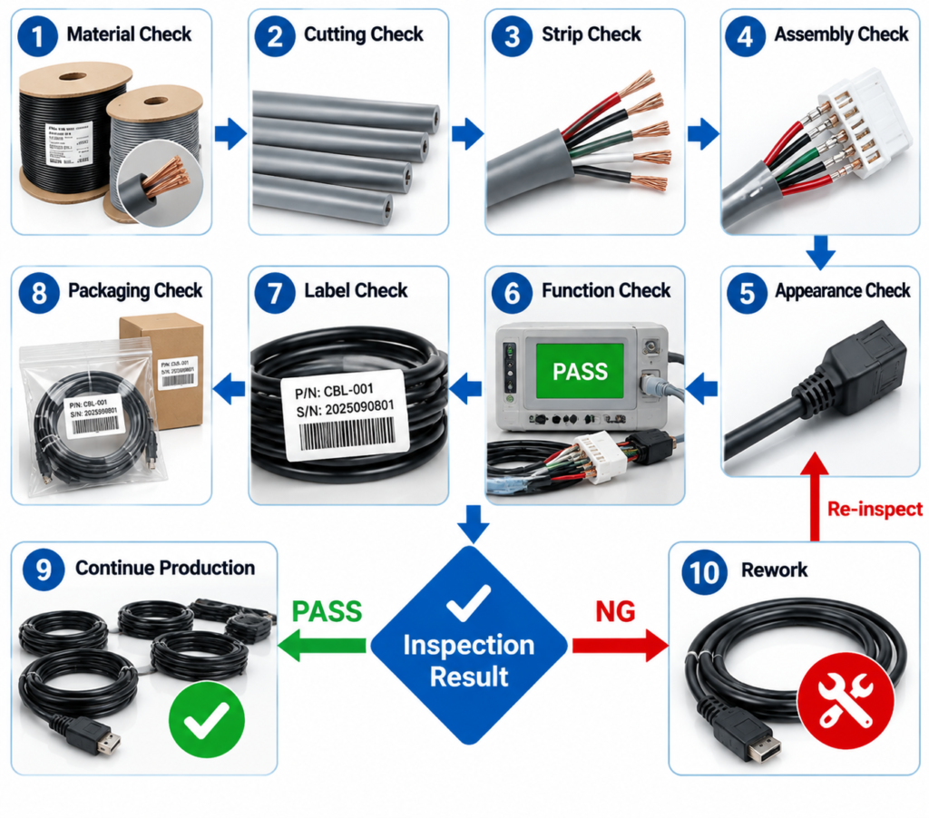
Cablivo uses a quality organization covering incoming inspection, production patrol inspection, finished-product review, reliability testing support and outgoing inspection. The objective is to connect project files with production execution and identify manufacturing issues before they develop into larger batch risks.
The Role Of IPQC In Cable Quality Control
IPQC works between incoming material inspection and outgoing quality control. Each stage answers a different question.
Incoming inspection asks whether wires, connectors, terminals, jacket materials, accessories and packaging components are suitable for production according to the approved project requirements. First-piece confirmation asks whether the production setup and initial output match the approved references. In-process inspection asks whether production continues to follow the agreed requirements as work progresses. Finished-product checks review completed cable function, dimensions or appearance according to the applicable specification. OQC connects product status with labeling, quantity, packaging, carton information and shipment preparation.
In-process inspection does not replace engineering review. A factory cannot confirm an undefined pinout, an unknown connector orientation or an unspecified tolerance through inspection alone. Clear project files remain the foundation of meaningful production control.
In-process inspection also does not mean every cable receives every possible test. Continuity, polarity, dimensional measurement, appearance review, connector fit discussion, pull-force requirements and functional checks serve different purposes. The selected methods should match the cable structure, application risk and confirmed quality plan.
For brands and engineering teams, the value lies in earlier visibility. A process issue identified before a large quantity moves into the next operation is usually easier to contain and review. Production records also give procurement and quality teams a clearer basis for discussing repeat orders, version changes and corrective follow-up.
The final goal is controlled manufacturing based on agreed requirements, not a broad promise of zero defects.

Two Cable Manufacturing Scopes Covered By Process Inspection
Cablivo supports inspection planning for both cable construction processes and cable assembly operations. The applicable checkpoints vary according to material structure, connector design, manufacturing method, approved files and final application.
Cable Extrusion And Construction
Custom cable production may begin with conductor preparation, insulation processing, inner jacket extrusion or outer jacket formation. Project-specific inspection can focus on characteristics related to cable construction before the cable enters connector assembly or harness production.
Possible review points may include:
- Approved conductor or wire structure
- Insulation and jacket material
- Cable diameter requirements
- Color and surface condition
- Shielding or protective construction
- Printing or identification
- Comparison with approved samples
- Material and production batch information
Inspection criteria must come from the agreed specification. A power cable, USB cable, industrial cable and network cable may have different structural requirements. Fixed tolerances or electrical values should not be assumed without a drawing, specification or approved sample.
Cable Assembly And Harnessing
Cable assembly production adds operations such as cutting, stripping, terminal crimping, soldering, connector assembly, housing insertion, wire harness routing, heat shrinking, overmolding, labeling and packaging preparation.
Possible in-process checkpoints may include:
- Total cable and branch lengths
- Stripping condition
- Terminal and wire matching
- Connector model and orientation
- Housing insertion
- Pinout and polarity
- Harness branch layout
- Sleeve and heat-shrink position
- Overmolded structure
- Label position and version
Inspection planning should follow the approved drawing, BOM, pinout table, connector information and production files. Complex wire harnesses may require different controls from a simple two-ended connector cable.
Where In-Process Inspection Fits In The Quality Path
Cable quality control begins before production and continues through manufacturing, finished-product review, packaging and shipment preparation. Each stage controls a different risk and relies on different project references.
Quality Stage
Main Purpose
Typical Project Inputs
Main Risk Addressed
Requirement Review
Define product and inspection requirements before production
Drawing, BOM, sample photos, connector datasheet, pinout, application information
Misunderstood specifications
Incoming Inspection
Review incoming wires, terminals, connectors, materials and packaging components
Final BOM, approved material information, packaging files
Incorrect components entering production
First-Piece Confirmation
Verify initial production output before broader release
Approved sample, final drawing, production instruction, inspection points
A full batch produced to an incorrect setup
In-Process Inspection
Check defined characteristics while production continues
Work instructions, approved files, inspection plan
Process deviations spreading through the batch
Finished-Product Review
Verify applicable function, dimensions, fit or appearance
Product specification, testing requirements, approved sample
Completed products failing agreed requirements
Packaging And OQC Review
Match product, quantity, label, SKU, packaging and carton information
SKU list, barcode file, packaging artwork, carton mark, packing requirements
Mislabeling, mixed versions and shipment errors
Cablivo’s documented quality position covers incoming material inspection, in-process inspection, finished-product inspection, reliability testing, packaging inspection and pre-shipment review according to product type and project requirements.
Why Global Project Teams Evaluate In-Process Inspection
Different project roles examine cable production from different angles. A useful inspection program connects engineering requirements, production risks, brand presentation, quality records and long-term supply needs without reducing every project to the same checklist.
Global Cable Brands
Cable brands need approved appearance, construction, labeling and packaging requirements to remain consistent when production moves from samples into larger quantities. In-process inspection helps review visible and hidden characteristics before products reach final packaging.
Brand-focused checkpoints may include cable color, connector direction, overmolded shape, logo position, surface condition, label version and packaging preparation. The final criteria should come from approved samples and controlled artwork files.
Clear process records also support later repeat orders when the same product returns in new quantities or packaging versions.
Engineering Teams
Engineering teams focus on functional accuracy and installation compatibility. A cable can appear correct while containing an incorrect pinout, polarity, terminal position, connector orientation or branch layout.
Production inspection should connect directly with drawings, wiring diagrams, connector datasheets, BOM revisions and approved samples. Early review becomes especially important before housings are closed, harnesses are bundled or connectors are overmolded.
Engineering teams gain a clearer basis for confirming whether production follows the intended structure rather than relying only on a finished appearance check.
Procurement Teams
Procurement teams need more than a competitive quotation. Supplier evaluation often includes questions about production controls, quality responsibilities, inspection records, batch identification and abnormal issue follow-up.
A manufacturer with defined inspection points can explain where production risks are reviewed and which project documents guide acceptance. Procurement can then compare suppliers on process capability rather than relying only on general claims.
Inspection planning also supports more accurate discussions about sampling, production quantities, special tests, labeling and packaging requirements before an order enters manufacturing.
Quality Teams
Quality teams usually look for evidence connecting inspection criteria with actual production. Important questions include who performs the inspection, when checks occur, how results are recorded, how affected work is separated and how corrected output is rechecked.
A meaningful control plan should distinguish incoming inspection, first-piece confirmation, production patrol checks, finished-product review and outgoing inspection.
Quality teams may also require project-specific records, photographs, measurement results or third-party test coordination. Requirements should be discussed before sampling or mass production.
Industrial Equipment Manufacturers
Industrial equipment projects often involve defined installation paths, multiple connectors, terminal housings, protective sleeves, branch dimensions and orientation requirements.
Production deviations can cause installation difficulty even when basic electrical continuity is correct. Inspection may need to cover branch layout, connector direction, wire labels, sleeve position, housing assembly and fit against the intended equipment interface.
Drawings, interface photographs, mating-part information and installation direction help Cablivo understand which checkpoints carry the highest project risk.
Long-Term Supply Programs
Long-term programs require more than one successful production batch. Approved samples, BOM revisions, label files, packaging versions and inspection records need controlled references for later production.
Batch identification and quality records help teams discuss previous output, version updates and recurring issues without restarting the entire confirmation process.
In-process inspection also supports repeat-order consistency by linking production activities with the same approved requirements. Any material, connector, label or packaging change should be reviewed before entering the next production batch.
Project Files Used To Define Cable Inspection Points
Reliable inspection begins with reliable references. The strongest quality plan connects production checkpoints with approved samples, controlled drawings, BOM versions, connector information, electrical definitions and packaging files.
Approved Cable Sample
An approved sample gives production and quality teams a physical reference for characteristics that may be difficult to communicate through text alone. It can support comparison of cable feel, connector direction, overmolded shape, branch arrangement, label position, color and final presentation.
The approved sample should not replace controlled documents. A complete reference may include:
- Sample version
- Approval date
- Drawing revision
- Material confirmation
- Connector information
- Appearance requirements
- Packaging version
- Recorded modifications
When a sample is revised, the updated version should be connected with the corresponding files before production release. Clear sample control reduces the risk of producing according to an outdated prototype.
Final Product Drawing
A final drawing converts product requirements into measurable and visible production information. Depending on cable type, the drawing may define total length, branch length, connector direction, exit direction, terminal position, sleeve location, label position and dimensional tolerances.
Inspection cannot confirm requirements that remain undefined. Useful drawing information may include:
- Product dimensions
- Measurement reference points
- Connector orientation
- Harness branch layout
- Pin numbering
- Label location
- Overmolded dimensions
- Revision identification
Cablivo can review available drawings before sampling or production. Missing details can be discussed together with sample photos, interface images or application information. Final inspection criteria should follow the approved drawing revision rather than an early draft.
Final Bill Of Materials
The final BOM identifies which wires, connectors, terminals, housings, sleeves, heat-shrink materials, labels and packaging components belong to the approved product version.
BOM control supports both incoming inspection and production execution. Review points may include:
- Part number
- Material description
- Connector model
- Terminal model
- Wire gauge
- Color
- Quantity per assembly
- Approved supplier information where applicable
- Revision or replacement status
A changed connector or terminal can affect crimping, fit, pinout and tooling. A changed jacket material can affect appearance, flexibility or processing. Any replacement should be evaluated before production rather than discovered during finished-product inspection.
Connector And Pinout Files
Connectors with similar appearances may have different keys, pin counts, dimensions, orientations or mating requirements. Pinout definitions also vary across equipment and applications.
Helpful project files may include:
- Connector manufacturer and model
- Male or female version
- Pin count
- Keying direction
- Housing drawing
- Mating-part model
- Pinout table
- Wiring diagram
- Polarity definition
- Interface photographs
Connector and pinout files guide assembly checks and electrical verification. Cablivo should not guess pin assignments from wire colors or connector appearance. Missing information can be discussed using old samples, equipment interface photos and engineering notes before the final production files are approved.
Testing Requirements
Testing requirements should match product function and project risk. A basic wire harness may need continuity and pinout verification, while a power cable, device cable or overmolded assembly may involve additional requirements.
Useful information may include:
- Test purpose
- Applicable product version
- Pinout or polarity definition
- Voltage or current information where relevant
- Mechanical stress location
- Required inspection stage
- Acceptance criteria
- Test report or record expectations
- Third-party testing requirements
No single test plan fits every cable. Special methods, equipment, fixtures, sample quantities, costs and timelines should be discussed before sampling or mass production.
Label And Packaging Files
Labeling and packaging errors can make an otherwise functional cable unsuitable for warehouse, distribution or retail use. Inspection criteria should therefore include approved packaging files when the project requires branded, multi-SKU or export packaging.
Helpful files may include:
- Product label
- Wire label
- Barcode file
- SKU list
- Packaging artwork
- Insert card
- Packing quantity
- Carton mark
- Packing sequence
- Language version
Production and inspection teams need clear version control. A label file used for one cable length or region should not be applied automatically to another SKU. Final files should be confirmed before packaging production begins.
Quality Teams Supporting Cable Production And Inspection
Cablivo’s quality organization covers incoming materials, production patrol inspection, finished products, reliability testing and quality feedback. Department responsibilities support different points in the manufacturing and delivery flow.
Quality Management
Cablivo’s quality department is coordinated by a quality manager responsible for team coordination, inspection-standard execution, abnormal issue follow-up and quality process management.
The role connects IQC, IPQC, OQC and reliability testing activities. For cable projects, quality management helps align production requirements with available inspection methods and promotes review when a deviation appears.
Project-specific inspection plans, reporting formats and special requirements should still be confirmed before production. Quality management does not replace engineering input or clearly approved product criteria.
28-Person IQC Team
The IQC team includes approximately 28 people supporting incoming checks before materials enter production.
Incoming materials may include:
- Wires
- Copper materials
- Jacket compounds
- Connectors
- Terminals
- Heat-shrink tubing
- Sleeves
- Labels
- Barcodes
- Packaging materials
- Cartons
- Other accessories
IQC work helps reduce the risk of incorrect components entering production and supports consistency between approved samples, final BOM information and later production batches. Inspection scope remains dependent on material type and project requirements.
42-Person IPQC Team
Cablivo’s IPQC team includes approximately 42 people supporting production patrol inspection.
The team covers manufacturing stages such as:
- Cutting
- Stripping
- Terminal crimping
- Soldering
- Injection molding
- Overmolding
- Heat shrinking
- Assembly
- Winding
- Packaging operations
IPQC aims to identify process issues while manufacturing remains underway. Inspection points are selected according to the product, agreed files and process risk. The presence of an IPQC team does not mean every project uses an identical checklist or inspection frequency.
30-Person OQC Team
The OQC team includes approximately 30 people supporting finished-product and shipment-related checks.
Depending on the order, outgoing inspection may review:
- Product appearance
- Applicable function
- Label information
- Packaging version
- Quantity
- SKU matching
- Carton information
- Shipment documentation
OQC connects product status with packaging and delivery preparation. It does not replace inspections carried out earlier in production. A problem hidden inside a finished assembly is usually better controlled before overmolding, bundling or packing.
Eight Laboratory Testers
Cablivo has approximately eight reliability laboratory testers supporting project-related testing activities.
Applicable testing depends on product structure, use conditions and agreed requirements. Possible discussions may involve continuity, insulation, pull force, bending, connector life or other reliability needs where suitable.
No universal test list, test value or pass guarantee should be applied to every cable. Required methods, sample quantities, fixtures, acceptance criteria, third-party arrangements and timelines need confirmation according to the individual project.
Quality Records And Feedback
Approximately three quality documentation and complaint-handling personnel support records and quality feedback coordination.
Useful records may connect:
- Approved samples
- Final BOM revisions
- Production batches
- Inspection results
- Label versions
- Packaging files
- OQC information
- Corrective follow-up
Quality records do not prove that production will never experience a deviation. Their value lies in traceability, review and repeat-order support. Record format and retention expectations should be discussed when a project requires specific quality documentation.
First-Piece Confirmation Before Full Production Release
First-piece confirmation checks whether the initial production output follows the approved sample and controlled project files before a broader quantity moves through the same manufacturing route.
Build The First Piece
The first production piece is created with the intended materials, tooling, work instructions and current file revisions.
Production preparation should confirm:
- Final BOM version
- Approved drawing
- Connector and terminal models
- Pinout or wiring information
- Approved sample
- Label file
- Packaging version
- Special inspection requirements
The purpose is to create an initial production reference under the planned manufacturing conditions. A prototype created during early development may not represent the final material, tooling or packaging arrangement. Production should therefore begin from the latest approved information.
Verify Critical Details
The first piece is reviewed against the checkpoints relevant to the product.
Possible review points may include:
- Total cable length
- Branch dimensions
- Connector model
- Connector direction
- Terminal and housing assembly
- Pinout and polarity
- Overmolded shape
- Cable exit direction
- Surface appearance
- Logo and label position
- Packaging version
Not every checkpoint applies to every cable. The final list should reflect the approved files and the main project risks. Any characteristic without a defined requirement should be clarified before broader production release.
Release Or Correct
Production release should follow successful confirmation of the agreed first-piece characteristics. If a deviation appears, the setup, materials, instruction or interpretation should be reviewed before the same condition affects a larger quantity.
Possible follow-up actions include:
- Hold further production
- Confirm the affected requirement
- Review files and samples
- Correct the setup or method
- Rebuild the first piece
- Recheck the relevant points
- Record the confirmed version
First-piece confirmation creates an early decision point between project files and mass production. It is not a substitute for continued in-process inspection during the remainder of the batch.
Cable In-Process Inspection Checkpoint Map
Production checkpoints should be placed before defects become hidden or expensive to correct. The map below links common cable manufacturing stages with possible inspection areas, project risks and supporting evidence.
Production Stage
Possible Inspection Points
Main Production Risk
Possible Evidence
Cable Construction
Material, cable diameter, color, surface, printing, approved structure
Unsuitable cable processed into completed assemblies
Incoming or process inspection record
Cutting
Cutting Total length, branch length, SKU length, quantity grouping
Installation failure or mixed-length production
Measurement or production record
Stripping
Strip length, insulation condition, conductor condition
Damaged strands or poor preparation for termination
Visual or first-piece record
Terminal Crimping
Terminal model, wire gauge match, crimp position, housing insertion
Loose or incorrectly assembled terminations
Inspection result or pull-force record where required
Soldering
Wire position, polarity, joint condition, insulation protection
Open circuit, short circuit or incorrect connection
Process check and applicable electrical verification
Connector Assembly
Connector model, orientation, keying, housing and mating information
Connector mismatch or installation failure
First-piece and fit review
Overmolding
Mold shape, connector position, cable exit direction, surface and logo position
Sample-to-production appearance or fit deviation
Approved-sample comparison
Harness Assembly
Branch layout, sleeve position, connector direction, wire labels and routing
Incorrect installation layout or identification
Assembly board or inspection record
Pre-Packing
Function where applicable, appearance, connector, label, SKU and quantity
Rework after packing or mixed versions
Pre-packing check
OQC
Product, packaging, carton mark, quantity and packing-list matching
Shipment and warehouse errors
OQC or packing record
Cable Extrusion And Construction Inspection Before Assembly
Cable construction affects every later operation. Material, diameter, surface, color and internal structure should be reviewed against approved requirements before the cable is cut, terminated, overmolded or assembled.
Construction Checks Before Connector Assembly
Cablivo’s extrusion workshop supports inner insulation and outer jacket production for custom cable projects. Construction requirements vary widely between power, USB, industrial, network and device cables, so inspection criteria need to follow the approved product definition.
Possible construction-related review points may include conductor or wire arrangement, insulation material, jacket material, cable outer diameter, color, surface condition, shielding construction, printing and identification. Any dimensional tolerance or material specification must come from approved drawings, material information or sample confirmation.
Cable inspection at the construction stage helps prevent unsuitable material from continuing into cutting and connector assembly. A cable with an incorrect diameter may not fit the intended connector boot or overmolded structure. An incorrect jacket material may affect processing, appearance or application suitability. A color variation may create problems for brand programs or multi-SKU identification.
Inspection should also consider the approved production version. A material change, supplier change or structural adjustment may require renewed sample discussion before mass production continues. Substitutions should not be treated as routine when they can influence function, appearance, compliance documentation or processing conditions.
For projects using externally supplied cable rather than in-house extrusion, incoming inspection and supplier material information become especially important. The same principle applies: the cable entering assembly should correspond with the approved product requirements.
Suggested Visual
Use a close-up cable construction board showing:
- Conductor or core
- Insulation
- Shielding where applicable
- Outer jacket
- Diameter measurement
- Approved color sample

Project Criteria And Production Release
Cable construction inspection needs clear acceptance criteria. A broad instruction such as “high quality cable” cannot guide production or inspection. Engineering and procurement teams should provide the information most relevant to the application.
Helpful information may include:
- Cable type and intended use
- Conductor requirement
- Wire gauge
- Core count
- Insulation material
- Jacket material
- Shielding structure
- Target diameter
- Color reference
- Printing requirement
- Flexibility or environmental expectations
- Applicable material documentation
The final criteria may be defined through drawings, technical specifications, approved material samples or agreed product samples. Where a numerical tolerance is important, the tolerance should be written and approved before production.

Construction checks should also be connected with later manufacturing. Cable diameter influences stripping setup, terminal selection, connector fit and overmolding. Jacket material influences cutting, stripping and molding behavior. Shielding affects termination and grounding methods. Inspection therefore works best as part of a connected production plan rather than an isolated measurement.
Cablivo can discuss inspection points during drawing review and sample development. Final methods, measuring tools, sampling arrangements and records depend on the cable structure and project requirements.
Cutting And Stripping Inspection Before Cable Termination
Cutting and stripping create the dimensional and conductor condition required for later crimping, soldering and assembly. Errors at either stage may remain hidden until installation or electrical testing.
Cutting To Approved Cable Lengths
Cable length affects equipment installation, wire harness routing, package size, SKU identification and repeat-order consistency. Inspection should use clearly defined measurement points rather than relying on an informal overall estimate.
Depending on product structure, cutting checks may include:
- Total cable length
- Exposed lead length
- Branch length
- Distance between breakout points
- Tolerance reference
- Length-specific SKU
- Quantity by length
- Cable label or identification
A wire harness may contain several branches with different dimensions. A cable kit may include multiple lengths packed together. A distributor program may use the same connector configuration across several length SKUs. Accurate length files help production separate these versions before assembly begins.

Measurement definitions also matter. Connector bodies, overmolded sections and exposed conductors can change the reference points used for total length. Drawings should show where measurement starts and ends. Where a connector or overmold is added later, the production instruction should explain how the cut length relates to the final finished length.
Cutting inspection should be completed before a large quantity moves into termination. Correcting an incorrect length after terminals, connectors or molded structures have been added may create extensive scrap or rework.
Stripping Without Hidden Conductor Damage
Stripping prepares the wire for terminal crimping, soldering or connector assembly. The operation removes insulation while preserving the conductor and required exposure length.
Possible inspection points may include:
- Strip length
- Insulation removal condition
- Conductor exposure
- Cut or damaged strands
- Remaining insulation near the termination
- Shield preparation where applicable
- Preparation for soldering or crimping
- Consistency with the work instruction
A stripping issue may affect terminal retention, electrical connection and later appearance. Damaged conductor strands can weaken a termination. Excessive exposed conductor may create electrical or workmanship concerns. Insufficient strip length may prevent correct insertion into a terminal or solder point.

Acceptance criteria depend on wire gauge, insulation type, terminal design and connection method. No single stripping dimension applies across all cable products.
First-piece confirmation should verify the stripping setup before broader production. Production patrol checks can then review whether the condition remains consistent. Where a machine setting, wire type or tooling condition changes, the relevant preparation should be rechecked.
Terminal And Crimping Inspection For Stable Cable Connections
Terminal crimping joins the wire conductor, insulation and terminal into a repeatable connection. Inspection should confirm material matching, assembly condition and any project-specific mechanical or electrical requirements.
Terminal, Wire And Housing Matching
A terminal must match the wire gauge, conductor type, connector housing and intended application. Similar-looking terminals may have different dimensions, plating, retention features or compatible wire ranges.
Before production, the BOM and connector information should identify:
- Terminal manufacturer or model where available
- Compatible housing
- Wire gauge
- Conductor type
- Insulation diameter
- Plating or material requirement
- Cavity position
- Applicable seal or accessory
- Insertion direction
- Pinout relationship

Production inspection can review whether the selected terminal and wire correspond with the approved files. Housing insertion should also be checked because a correctly crimped terminal placed into the wrong cavity still creates a functional failure.
Visible workmanship points may include conductor position, insulation position, terminal deformation, exposed strands and housing seating. The exact acceptance criteria should follow the terminal specification, approved sample or agreed workmanship standard.
For multi-cavity connectors, inspection should connect terminal position with the pinout table. Wire colors alone should not be used as the only reference when a wiring diagram or numbered pin definition is available.
Crimp Acceptance And Follow-Up Requirements
Crimp inspection should focus on the connection characteristics relevant to the selected terminal and wire. Depending on project requirements, review may involve appearance, dimensional checks, terminal retention, continuity or pull-force discussion.
Possible checks may include:
- Correct terminal model
- Correct wire gauge
- Conductor placement
- Insulation support
- Crimp position
- Terminal deformation
- Housing insertion
- Locking condition
- Applicable continuity verification
- Mechanical test requirement where specified
Fixed crimp-height values, pull-force values or test frequencies cannot be applied without the terminal specification and approved quality plan. Different terminals, conductor sizes, materials and applications require different criteria.

Where pull-force testing is required, the project should define the purpose, test location, sample plan and acceptance value. A terminal crimp, molded strain relief and connector cable exit are different structures and should not share an assumed requirement.
Production should also consider changes. A new terminal lot, changed wire gauge, adjusted tool or revised housing may require renewed confirmation. Any additional process validation should be discussed before production.
Soldering Connector Assembly And Pinout Inspection Controls
Soldered connections, connector assembly and wire sequence determine whether a completed cable fits the intended interface and performs the required connection. Inspection needs approved electrical and mechanical references.
Soldering And Connector Assembly
Soldering may be used where wires connect directly to terminals, contacts, boards or internal connector structures. The production instruction should define wire preparation, solder location, polarity, insulation protection and assembly sequence.
Possible soldering review points may include:
- Correct wire and contact
- Wire position
- Polarity
- Solder joint condition
- Unwanted solder bridging
- Insulation clearance
- Strain protection
- Clean assembly
- Applicable continuity check
The final criteria should match product structure and agreed workmanship requirements. A general visual statement cannot replace defined acceptance examples where soldering carries functional risk.

Connector assembly adds another set of checks. Connector model, male or female version, pin count, keying direction, housing orientation and cable exit direction should correspond with the project files. A connector can look similar to another series while using a different mating key or dimension.
Pinout Polarity And Electrical Mapping
Pinout defines which conductor connects to each terminal or connector position. Polarity defines positive, negative or directional electrical relationships where applicable. Both need approved references.
Useful information may include:
- Pinout table
- Wiring diagram
- Connector cavity numbering
- Wire color definition
- Signal or power designation
- Positive and negative polarity
- Shield or drain-wire connection
- Branch destination
- Terminal numbering
- Test method

Cablivo should not guess pin assignments from connector appearance or common market use. The same connector may support different pinouts across equipment models.
During production, pinout inspection may connect wire preparation, terminal insertion, connector assembly and continuity verification. A complex wire harness may require branch-by-branch mapping. A power cable may require polarity confirmation. A sensor cable may require signal, power and shield relationships to be checked separately.
Where an old sample is the only reference, sample review should be combined with interface information and a confirmed wiring definition before production. Old samples can contain unknown revisions or previous manufacturing errors.
Overmolding Harness Assembly And Identification Inspection
Overmolding and harness assembly can hide earlier operations and define final installation geometry. Inspection should compare production with approved samples, drawings and labeling files before correction becomes difficult.
Overmolded Cable Structure And Appearance
Overmolding can protect a connector termination, create strain relief, form a branded housing or control cable exit direction. The molded result must remain compatible with the connector, cable, equipment interface and approved appearance.
Possible in-process review points may include:
- Connector position
- Molded shape
- Overall dimensions where specified
- Cable exit direction
- Surface condition
- Color
- Logo position
- Flash or visible molding condition
- Cable-to-mold transition
- Comparison with approved sample

The approved sample is especially valuable for molded appearance and geometry. Drawings should still define any dimensions or orientation requirements that cannot rely on visual comparison alone.
Overmolding checks should begin before a large quantity is completed. A connector inserted in the wrong direction, an incorrect cable exit angle or an unsuitable mold setup can affect every unit produced under the same condition.
No unverified durability value, bend-cycle result, sealing level or waterproof rating should be claimed without actual product design and testing. Overmolding can support protection and strain-relief design, but final performance depends on material, structure, application and validation.
Harness Layout Labels And Protective Components
Wire harness inspection needs to consider the assembled geometry, not only the individual wires. Branch positions, connector directions, protective sleeves and labels affect installation and service.
Possible review points may include:
- Total harness layout
- Branch length
- Breakout position
- Connector orientation
- Terminal housing position
- Sleeve length
- Heat-shrink position
- Protective tubing
- Cable ties or fastening points
- Wire labels
- Product labels
- Installation direction

An assembly board or fixture may support repeat positioning for complex harnesses where appropriate. Fixture use should be discussed according to harness drawing, branch layout and production quantity rather than presented as mandatory for every project.
Wire identification also needs controlled files. Label text, sequence, position and direction should match the approved wiring or installation plan. A correct electrical connection can still create installation problems when labels are missing, reversed or attached to the wrong branch.
Before packing, harness layout and identification should be reviewed together with the intended packaging method. Tight bending, incorrect coiling or mixed labels can undo earlier production control.
Project-Specific Methods Used For Cable Process Inspection
Inspection methods should match the characteristic being controlled. Dimensions, workmanship, electrical mapping, connector fit, mechanical requirements and application functions require different references and acceptance criteria.
Dimensional Checks
Dimensional checks help confirm whether cable and harness geometry follows the approved drawing.
Possible characteristics may include:
- Total cable length
- Branch length
- Strip length
- Exposed wire length
- Label position
- Sleeve position
- Connector orientation
- Molded dimensions
- Harness breakout location
Measurement points and tolerances must be clearly defined. A total cable length measured between connector faces differs from a cut-wire length measured before termination.
Workmanship Inspection
Workmanship inspection reviews visible production characteristics against approved examples, drawings or workmanship criteria.
Possible areas may include:
- Stripping condition
- Conductor condition
- Crimp appearance
- Solder joint appearance
- Housing insertion
- Heat-shrink placement
- Overmolded surface
- Cable jacket condition
- Label application
- General assembly cleanliness
Photographs or approved samples can help communicate acceptable and unacceptable conditions. Visual inspection should not be used as a substitute for dimensional or electrical verification when a characteristic cannot be judged by appearance.
Connection Verification
Connection verification confirms whether conductors, terminals, connectors and branches follow the approved electrical map.
Depending on the product, verification may include:
- Continuity
- Pin-to-pin mapping
- Branch connection
- Terminal connection
- Polarity
- Shield connection
- Open-circuit identification
- Short-circuit identification
The approved pinout table or wiring diagram is essential. A tester cannot determine the intended result without a defined connection map.
Connector Fit Review
Connector fit review focuses on mechanical compatibility with the mating interface.
Useful reference information may include:
- Connector model
- Mating connector model
- Keying direction
- Housing dimensions
- Pin count
- Locking feature
- Cable exit direction
- Equipment interface photos
- Existing samples
A visually similar connector may not mate correctly. Fit review is most effective before large quantities are assembled or overmolded.
Mechanical Requirements
Mechanical requirements vary according to the cable structure and application. Possible discussions may include terminal retention, connector cable exit, molded strain relief or harness fastening points.
Relevant information may include:
- Expected load location
- Pull direction
- Wire gauge
- Terminal model
- Connector construction
- Strain-relief design
- Application movement
- Required test method
- Acceptance value
- Sample quantity
No universal pull-force or bend value applies across all cables. Test requirements should be approved before sampling or production, especially when special fixtures, additional samples or third-party testing may be required.
Application Function Checks
Functional checks should reflect what the cable needs to do in the intended equipment or product.
Possible areas may include:
- Power connection
- Charging function
- Data communication
- Device recognition
- Sensor connection
- Control signal
- Equipment interface fit
- Cable kit completeness
A broad request such as “fast charging cable” or “data cable” is not a complete test specification. Interface, target performance, device information, applicable protocol and test conditions may be needed.
Mid-Production Patrol Inspection And Process Recheck
Production conditions can change after first-piece approval. Patrol inspection and defined recheck points help confirm that later output continues to follow the approved sample, files and process requirements.
When A Production Recheck May Be Needed
First-piece approval confirms the starting condition, but production continues after the first unit. Materials are consumed, operators complete repeated cycles, tooling experiences use and work moves between production stages.
Depending on product and process risk, a recheck may be considered:
- At production startup
- After first-piece approval
- During production patrol
- At a defined batch point
- After a material lot change
- After a terminal or connector lot change
- After a tooling adjustment
- After a machine setup change
- After a production interruption
- After a corrective action
- Before transfer into overmolding
- Before packing

The selected points should focus on characteristics with meaningful project impact. A wire harness may require branch-layout and connector-position checks. A terminal cable may focus on stripping, crimping and housing insertion. A molded cable may require connector orientation and molded-structure comparison.
Patrol inspection is not intended to create unnecessary repeated checks. The purpose is to detect meaningful drift or repeated production mistakes before a larger quantity advances.
Inspection results should be connected with the batch or production stage where required. Any abnormal result needs review before relying on later finished-product inspection to identify the same issue.
Inspection Frequency Remains Project-Based
No universal inspection interval fits every cable product. A fixed statement such as “checked every hour” or “one piece per 100 units” may be inappropriate without considering product complexity, process stability, order quantity and project risk.
Inspection frequency may depend on:
- Cable type
- Manufacturing operation
- Batch quantity
- Product complexity
- New or repeat production
- Material stability
- Tooling condition
- Critical dimensions
- Safety or functional risk
- Brand appearance requirements
- Quality history
- Agreed quality plan
Additional checks can affect manufacturing time and labor. Special measurements, detailed records, test fixtures or third-party requirements may also influence sample preparation and production scheduling.

Cablivo should confirm the inspection plan after reviewing drawings, approved samples, connector information, quantity, testing requirements and packaging needs. No fixed sample time or delivery time should be published before the project scope is known.
For long-term supply programs, inspection history can support later review of whether checkpoints should remain, increase or change for a future batch.
Nonconforming Product Containment And Corrective Follow-Up
Finding a deviation is only the first step. An effective response needs clear identification, separation, review, correction, reinspection and records before affected work returns to the production flow.
Identify Hold And Separate Affected Work
When an in-process inspection result does not match the approved requirement, production should not treat the condition as a minor visual observation without review.
The first response should establish:
- Which requirement was not met
- Which operation created or revealed the issue
- Which production quantity may be affected
- Whether later operations have already begun
- Whether the condition affects function, fit, appearance or labeling
- Whether production should pause
- How affected material or work-in-progress should be identified
- Which files or samples need to be reviewed
Affected work should be separated from confirmed output to reduce the risk of mixing. Identification may involve production status, batch information, workstation information or physical segregation according to the project and internal control method.

The review may need participation from quality, engineering, production management or material teams. A connector mismatch requires a different response from a label-position issue. A pinout deviation may require electrical mapping review, while an overmolding deviation may require setup or tooling discussion.
The goal is to define the affected scope before correction begins. Reworking isolated pieces without understanding the cause can allow the same condition to continue elsewhere in the batch.
Correct Recheck Record And Release
Corrective follow-up should address both the immediate output and the production condition that created the deviation.
Possible steps may include:
- Confirm the correct drawing or file revision
- Review the approved sample
- Check material and connector information
- Adjust the production setup
- Update or clarify the work instruction
- Rebuild a first piece
- Reinspect the affected characteristic
- Review affected work-in-progress
- Record the correction and result
- Release production after confirmation
Where a deviation may affect delivered function, fit, appearance or packaging, communication requirements should be agreed with the project contact.

A corrected item should be rechecked using the same relevant acceptance criteria. If the correction changes material, structure, appearance or another approved characteristic, further sample confirmation may be required.
Records can support later review, repeat orders and corrective improvement. They do not replace prevention, but they provide a clearer account of what happened and how production returned to an approved condition.
Inspection Records Traceability And Supplier Review Evidence
Quality records connect approved requirements with production batches, inspection results, packaging versions and later repeat orders. Record expectations should be discussed according to project risk and documentation needs.
Record Or Evidence
Information Connected
Value For Project Teams
Approved Sample Record
Sample version, drawing revision, materials and appearance
Establishes a physical production reference
Final Drawing Revision
Dimensions, orientation, branch layout and labels
Reduces outdated-file production
Final BOM Revision
Wires, connectors, terminals, accessories and packaging components
Supports material and component control
First-Piece Check Record
Initial production output and release checkpoints
Shows whether production started from the approved condition
In-Process Inspection Record
Production stage, inspected characteristic and result
Supports process review and abnormal issue analysis
Nonconformance Record
Deviation, affected scope and disposition
Supports containment and corrective follow-up
Reinspection Record
Corrected output and verification result
Shows whether the affected characteristic was rechecked
Production Batch Record
Order, date, material, SKU or production information
Supports traceability and repeat-order review
Label And Packaging Files
Barcode, SKU, artwork, carton mark and packaging version
Reduces version confusion
OQC Record
Product, quantity, packaging and shipment-related checks
Connects production with delivery preparation
Cable In-Process Inspection Frequently Asked Questions
Find direct answers about cable IPQC, first-piece approval, inspection criteria, production checkpoints, quality records and abnormal issue follow-up.
What Is Cable In-Process Inspection?
Cable in-process inspection checks defined product and workmanship characteristics while manufacturing is underway. Possible stages include cutting, stripping, crimping, soldering, connector assembly, harnessing, overmolding, labeling and pre-packing. The exact checkpoints depend on cable type, approved samples, drawings, BOM information and project requirements. The objective is to identify deviations before a larger production quantity continues through later operations.
How Is IPQC Different From Final Inspection?
IPQC reviews production output during manufacturing. Final inspection reviews a completed cable or harness after the main production operations are finished. IPQC can identify problems before they become hidden by housings, sleeves, overmolding or packaging. Final inspection remains important for applicable function, appearance and dimensions. Both stages serve different purposes and should be connected with incoming inspection and OQC.
Which Cable Production Stages Can Be Inspected?
Inspection may cover cable construction, cutting, stripping, terminal crimping, soldering, connector assembly, housing insertion, heat shrinking, harness routing, overmolding, labeling and packaging preparation. Not every stage applies to every product. A wire harness, extruded cable and molded connector cable need different checkpoints. Cablivo reviews the product structure and project files before discussing the inspection plan.
What Documents Define Inspection Criteria?
Common references include approved samples, final drawings, final BOM revisions, connector datasheets, pinout tables, wiring diagrams, material information, work instructions, testing requirements, label files and packaging artwork. Numerical tolerances or special acceptance values should be written and approved. Inspection cannot verify an undefined requirement, so incomplete files should be discussed before production begins.
Is First-Piece Confirmation Required Before Production?
First-piece confirmation is valuable for projects where production setup, materials, connectors, terminal positions, dimensions, overmolding, labels or packaging need verification before a larger quantity is released. The required checkpoints depend on product and process risk. First-piece approval does not replace continued IPQC because conditions can change during later production.
What Is Checked During Terminal Crimping?
Possible checks include terminal model, wire gauge match, conductor position, insulation position, visible crimp condition, terminal insertion, housing position and applicable continuity or mechanical requirements. Fixed crimp-height or pull-force values depend on the terminal, conductor and approved specification. Cablivo needs terminal information, wire details and project requirements before confirming the final inspection method.
How Is Cable Pinout Verified During Production?
Pinout verification uses an approved pinout table, wiring diagram or confirmed electrical map. Production checks may connect wire preparation, terminal insertion, housing cavity position and continuity verification. Wire color alone should not be treated as the only reference. Engineering teams should provide connector numbering, polarity information and branch definitions where applicable.
How Is Mid-Production Inspection Frequency Decided?
Frequency depends on cable complexity, process risk, batch quantity, production history, material or tooling changes, critical characteristics and agreed quality requirements. No universal hourly or unit-based interval fits every cable. Cablivo discusses inspection points after reviewing the product, production route, quantity, testing requirements and required records.
What Happens When A Production Deviation Is Found?
The affected requirement and production scope should first be identified. Relevant work may need to be held and separated while quality, engineering or production teams review the cause. After correction, the affected characteristic should be rechecked before production release. Record format and communication requirements depend on project risk and the agreed quality plan.
Can Additional Inspection Affect Project Timing?
Yes. Special fixtures, detailed measurement records, additional sample quantities, mechanical validation, third-party testing or complex packaging checks may influence sample preparation and production time. Cablivo confirms timing after reviewing product structure, connector availability, tooling, quantity, inspection methods and packaging requirements. No fixed universal sample or delivery period is stated before project review.
Send Your Cable Inspection Requirements
Share the available information for your cable, wire harness or cable assembly project. Cablivo can review the manufacturing route, approved references and production risks before discussing first-piece confirmation and in-process inspection points.
Useful information may include drawings, BOM revisions, approved sample photos, connector models, pinout tables, wiring diagrams, cable lengths, branch dimensions, terminal specifications, target quantities, testing requirements, label files and packaging artwork.
Complete documentation is not required for the first contact. Existing samples, interface photographs or a partial specification can provide a starting point. Missing details can be identified during the review.
Inspection methods, sampling points, quality records, sample timing and production timing depend on product structure, material availability, tooling, order quantity and agreed requirements. Special measurement, reliability testing or third-party testing needs should be discussed before sampling or mass production.
Cablivo supports project communication from engineering review and sample development through production inspection, packaging and shipment coordination.
