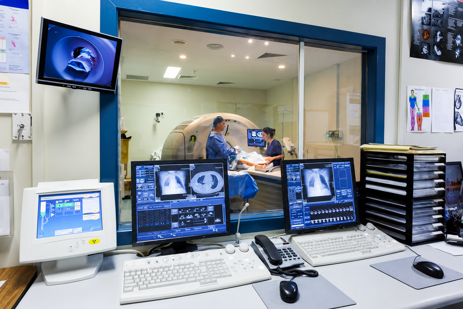
Cable Assembly for Diagnostic Device Engineering Teams
Engineering-led cable assembly support from device interface review and prototype validation to controlled production, inspection, packaging, and shipment coordination.
Cablivo helps diagnostic device engineering teams convert drawings, interface information, existing samples, and BOM files into production-ready cable assemblies.
- Review drawings, BOM files, interface photos, connector data, and application notes.
- Confirm connector type, pinout, cable length, AWG, material, shielding, and assembly structure.
- Develop prototypes for fit, function, appearance, labeling, and packaging evaluation.
- Prepare confirmed specifications for production, inspection, packing, and repeat-order coordination.
18 +Years
Cable experience
20,000+ m²
Factory space
1,500+ People
Cross-functional team
3 Bases
Manufacturing bases
Cable Assembly Support Across Diagnostic Device Project Types
Diagnostic equipment may require power, signal, data, sensor, internal, and external connections within one system. Cablivo reviews each project according to device application, interface definition, installation conditions, verification requirements, expected quantity, and production plans.

Diagnostic Equipment Platforms
Diagnostic platforms often combine several connection functions inside one machine, including power delivery, signal transfer, data communication, sensor feedback, and internal module interconnection. Engineering review may cover connector selection, cable routing, pinout, wire gauge, shielding, branch layout, installation space, labels, and access for assembly. Drawings, interface photographs, BOM files, or existing samples help establish an accurate starting point. Prototype evaluation should confirm device fit, connection direction, cable length, functional requirements, and assembly convenience before final specifications move into production preparation.

Laboratory Instruments
Laboratory instruments may use cable assemblies between analytical modules, sample-handling units, sensors, displays, control boards, power supplies, and external accessories. Space limitations, repeated maintenance, connector orientation, cable identification, and routing order can affect assembly efficiency. A project review should identify the instrument function, installation position, cable length, connector model, branch requirements, labeling plan, and expected verification method. For instruments with several models or configurations, a clear SKU and revision structure helps prevent incorrect assembly, labeling, packing, or repeat-order execution.

Monitoring Systems
Monitoring systems can include patient-side leads, sensor connections, control cables, power assemblies, data cables, and internal wire harnesses. Specifications vary according to device design, signal definition, connection frequency, cable flexibility, installation environment, and cleaning requirements. Cablivo can review supplied drawings, connector details, pinout tables, material preferences, cable length, label position, and packaging instructions before sampling. Testing and inspection items should be defined according to product function and application rather than assumed from a standard checklist. Final suitability remains subject to confirmed project specifications.

Sensor-Based Devices
Sensor-based diagnostic equipment depends on accurate wiring relationships between sensors, control boards, display units, power modules, and processing components. Similar-looking connectors or unclear wire definitions may create functional errors during prototype development. Engineering teams should provide connector datasheets, device interface photographs, pinout tables, cable length, wire color definitions, shielding requirements, and sensor application notes whenever available. Prototype checks may include connector fit, continuity, polarity, wire sequence, length, appearance, and label verification. Confirmed samples and files then provide a clearer reference for production preparation.

Portable Diagnostic Units
Portable diagnostic devices often require compact cable routing, low-profile connectors, controlled cable exits, flexible structures, and protection around frequently handled connection points. Product development may involve standard connectors, custom molded ends, internal harnesses, detachable accessories, or combined power and signal assemblies. Cablivo can discuss cable diameter, jacket direction, flexibility, connector protection, strain relief, overall length, and packing format according to device design. Prototype review should verify fit, handling, connection direction, and structural appearance before final files are released for production.

Healthcare Electronics
Healthcare electronics projects may involve device cables, charging assemblies, power leads, signal cables, internal harnesses, sensor connections, or accessory cable kits. Requirements can differ by device function, target market, operating environment, packaging plan, and documentation needs. Project discussions may cover connector compatibility, cable structure, materials, labels, inspection items, packaging, and NDA requirements. Regulatory, material, or third-party testing needs must be reviewed according to the actual device, intended market, and supplied requirement list. No universal medical compliance claim should be assumed without project-specific documentation.
What Engineering Teams Expect From a Manufacturing Partner
A diagnostic cable program involves more than producing wires with connectors. Engineering groups need clear technical review, controlled prototype development, documented confirmation points, repeatable production preparation, defined inspection requirements, and dependable communication across every project stage.
Technical File Interpretation
Engineering files must be converted into clear manufacturing instructions before materials are prepared or samples are built. A capable manufacturing partner should review the information rather than quote from a single photograph.
- Mechanical or electrical drawings
- BOM files
- Connector datasheets
- Pinout tables
- Existing sample photographs
- Device interface photographs
- Length and tolerance requirements
- Application and installation notes
Interface Accuracy
Connector compatibility must be established through model numbers, datasheets, physical samples, interface photographs, or fit evaluation. Two connectors may appear similar while differing in pitch, keying, orientation, housing shape, terminal design, or locking method.
- Connector manufacturer and model
- Pin count and pitch
- Male or female orientation
- Keying and locking structure
- Terminal and housing combination
- Cable exit direction
- Mating interface
- Expected insertion conditions
A protot
A prototype should create a measurable reference for engineering approval rather than serve as a visual sales sample. Validation may cover physical fit, cable length, connector direction, wire sequence, polarity, material appearance, flexibility, labeling, overmolding, and packaging.
- Review of supplied files
- First-sample preparation
- Internal inspection
- Photographic or video confirmation
- Physical sample delivery
- Written feedback collection
- Revision-point confirmation
- Approved-sample identification
Production Repeatability
A successful prototype does not automatically guarantee accurate mass production. Production preparation requires approved references and controlled files that define what must remain unchanged.
- Approved physical sample
- Final drawing
- Final BOM
- Confirmed connector source
- Pinout and wire-color definition
- Material and jacket requirements
- Label and packaging files
- Inspection checklist
- Approved revision number
Testing Clarity
The phrase “fully tested” has little value unless the inspection objects, acceptance requirements, and reporting expectations are defined. Diagnostic equipment projects may require different checks according to cable function and device risk.
- Continuity
- Pinout
- Polarity
- Open and short circuits
- Connector fit
- Cable length
- Pull-force requirements
- Insulation or Hi-Pot requirements
- Appearance
- Label and packaging inspection
- Outgoing quality control
Version Discipline
Diagnostic devices may evolve through prototype, verification, pilot, production, and repeat-order stages. Cable drawings, connectors, labels, packaging, and test requirements can change during development.
- Original file version
- Prototype version
- Revised sample version
- Approved production version
- Label version
- Packaging version
- Repeat-order version
- Engineering change details
Six Risks That Derail Diagnostic Cable Assembly Programs
Small specification gaps can create large problems during device integration, prototype verification, production, or field installation. Each risk below should be addressed through engineering review, documented confirmation, sample validation, and controlled production files.
Misread Drawings
An unclear dimension, tolerance, connector direction, branch position, or label location can change how an assembly fits inside the device. Drawing review should compare mechanical information with the application, BOM, connector datasheet, and available sample photographs. Missing or conflicting details should be clarified before material preparation. A marked drawing, revision note, or confirmation list creates a better reference than relying on messages spread across several email threads.
Wrong Connectors
Connector families often contain visually similar housings with different pitch, keying, pin count, terminal, or orientation. Selecting a part from appearance alone may result in failed mating or incorrect installation. Connector model numbers, datasheets, clear close-up photographs, mating-interface information, or physical samples should be reviewed before sampling. Availability should also be checked early because sourcing conditions can affect prototype timing, minimum quantity, tooling, and production planning.
Unconfirmed Pinout
Wire sequence and polarity cannot be inferred safely from insulation colors or connector position. A wrong circuit relationship may prevent the device from operating or may create difficult troubleshooting during system verification. Engineering teams should provide a pinout table, wiring diagram, old-sample reference, or defined test method. Pinout, polarity, wire color, shielding termination, and connector orientation should be confirmed before a sample is approved for production.
Material Mismatch
Cable materials affect flexibility, diameter, appearance, abrasion behavior, handling, cost, processing, and installation. A material selected only by name may not suit the device environment or mechanical layout. Application notes should explain required flexibility, routing, movement, appearance, cleaning conditions, temperature direction, and expected service environment. Material selection remains subject to engineering review, sample evaluation, availability, and confirmed project specifications.
Prototype Drift
A prototype may perform correctly while production uses an unconfirmed BOM, different connector source, revised label, changed cable length, or altered overmold structure. Approved samples must be linked to final drawings, BOM files, inspection points, and packaging instructions. Production preparation should use the approved configuration rather than an earlier quotation or informal photograph. Any later change requires a documented review before materials or tooling are updated.
Revision Confusion
Several sample rounds, device versions, connector substitutions, and packaging updates can create overlapping files. Production teams may receive an outdated drawing while quality teams use a newer checklist. A single approved revision set should contain the drawing, BOM, pinout, sample reference, label, packaging, and inspection requirements. Repeat orders should begin with a version comparison, especially when previous quantities, connectors, materials, or artwork have changed.
Cable Assembly Configurations for Diagnostic Device Integration
Cablivo supports project-based cable assemblies developed around device function, interface definition, installation space, connector requirements, cable construction, inspection needs, labeling, and packaging. Final configurations are determined after reviewing available engineering information.

Power Cable Assemblies
Power cable assemblies may connect internal power supplies, batteries, control boards, displays, external adapters, or device modules. Engineering review should confirm connector type, polarity, wire gauge, conductor count, cable length, jacket direction, branch structure, and installation conditions. Voltage, current, insulation, or target-market requirements must come from the device specification rather than assumptions. Prototype evaluation may cover connector fit, polarity, continuity, length, assembly routing, labeling, and appearance. Packaging should protect the connector and maintain clear product identification during storage and assembly.

Signal and Data Assemblies
Signal and data assemblies may connect diagnostic modules, sensors, control units, displays, communication boards, or external accessories. Cable construction can depend on interface type, pinout, shielding, pair arrangement, jacket, connector orientation, bend direction, and installation length. Engineering groups should provide functional descriptions, connector datasheets, wiring information, and any required electrical or signal verification methods. Cablivo can review structure and manufacturability before sampling. Performance claims should only be defined after the interface, cable construction, test method, and device requirements are confirmed.

Sensor Cable Assemblies
Sensor assemblies require accurate connection between the sensing element, device interface, internal board, or processing module. Pinout, polarity, shielding termination, wire color, connector orientation, and mechanical protection are frequent review points. Compact sensors may also require small housings, controlled cable exits, low-profile overmolding, or flexible cable structures. Prototype validation should confirm fit, function, length, cable movement, labeling, and visual consistency. Any sensitivity, accuracy, signal, or environmental requirement must be supplied and verified according to the final device specification and agreed inspection method.

Internal Wire Harnesses
Internal harnesses may contain several branches, terminals, housings, sleeves, heat-shrink tubes, ties, labels, and mounting directions. A harness drawing should identify branch length, breakout position, wire gauge, connector model, terminal, wire color, label, routing, and tolerance. Engineering review should also consider assembly access and installation order inside the equipment. Sample validation can include branch dimensions, terminal insertion, connector fit, continuity, pinout, label position, and appearance. Final harness files should be organized clearly before repeatable production begins.

Multi-Connector Assemblies
Multi-connector assemblies combine several interfaces within one finished unit. Different ends may support power, communication, sensors, controls, or accessories. Complexity increases when the assembly contains branches, mixed connector families, individual labels, sleeves, or different cable constructions. A complete drawing and BOM help define every connection. Pinout tables should identify the relationship between each end. Prototype review may include mating, routing, branch orientation, continuity, polarity, dimensions, overmolding, and packaging. Each connector and branch should remain traceable to the approved specification.

Overmolded Assemblies
Overmolding can protect connector transitions, create strain relief, manage cable exit direction, improve handling, or support a defined product appearance. Development may require a drawing, physical sample, connector model, overmold dimensions, surface direction, material discussion, color, and logo position. Tooling feasibility should be evaluated before sampling. The first overmolded sample should confirm fit, appearance, cable exit, connector exposure, and device clearance. Final mold and sample approval then provide a stronger production reference for repeated assemblies.
Specifications Required Before Accurate Cable Assembly Development Begins
A complete specification reduces quotation uncertainty, connector errors, sample revisions, and production changes. Missing information does not prevent an initial discussion, but every critical parameter must be confirmed before final sampling and production approval.
Specification
Why It Matters
Information to Confirm
Recommended Input
Device Application
Defines function, environment, installation, and risk
Device type, connection purpose, internal or external use
Application notes and equipment photos
Connector
Determines mating compatibility
Model, pin count, pitch, keying, gender, orientation
Datasheet, clear photos, or physical sample
Pinout
Defines electrical relationship
Circuit sequence, polarity, wire color, grounding
Pinout table or wiring diagram
Cable Length
Affects routing and installation
Overall length, branch length, tolerance, measurement method
Drawing or length list
Wire Gauge
Influences cable structure and intended electrical use
AWG, conductor count, conductor construction
BOM or engineering specification
Shielding
Relates to signal structure and grounding design
Foil, braid, drain wire, termination direction
Electrical requirements and application notes
Jacket
Affects flexibility, diameter, appearance, and environment
Material direction, color, surface, flexibility
Material requirements or reference sample
Overmolding
Affects connector protection and cable exit
Shape, dimensions, material, color, surface, logo
Drawing, 3D file, sample, or marked photographs
Labeling
Supports identification and assembly control
Text, position, material, serial or model information
Label artwork and placement drawing
Testing
Defines verification before approval and shipment
Electrical, mechanical, visual, packaging, or functional checks
Test specification or acceptance checklist
Branch Layout
Controls internal routing and assembly access
Breakout position, branch direction, tie and sleeve positions
Harness drawing
Packaging
Protects finished assemblies and supports identification
Bag, box, divider, quantity, barcode, carton mark
Packaging file and packing instructions
Files That Make Engineering Review Faster and More Accurate
Engineering review can begin with partial information, but organized project files shorten repeated clarification. Six information groups below help Cablivo understand the device, assembly structure, verification method, expected volume, and delivery requirements.
Product References
Useful product references include cable drawings, marked photographs, sketches, existing cable samples, and equipment interface images. These inputs show the visible structure, connector position, cable direction, branch layout, label location, and installation space. Clear photographs should include the entire assembly and close-ups of each connector. A ruler or dimensional note can provide scale when a drawing is unavailable. Product references should identify whether the objective involves copying, correcting, replacing, or developing a new assembly.
Engineering Definition
Engineering files may include BOM sheets, connector datasheets, pinout tables, wiring diagrams, AWG requirements, shielding direction, branch dimensions, tolerances, and overmold specifications. Conflicting information should be highlighted rather than left for interpretation. Revision numbers and approval status should appear on important files. Where final details are not yet available, engineering groups can identify open items so the first review focuses on decisions that affect feasibility, sourcing, tooling, prototype scope, and quotation accuracy.
Application Context
Application information explains where and how the assembly operates. Helpful details include device category, internal or external installation, fixed or moving use, available routing space, connection frequency, handling direction, appearance requirements, and relevant environmental conditions. Application context helps determine which questions should be asked about material, flexibility, shielding, protection, connector retention, labeling, and packaging. It does not replace formal specifications, but it prevents technical decisions from being made without understanding the device.
Verification Plan
A verification plan identifies what must be checked before a sample or production lot is accepted. Inputs may include continuity, pinout, polarity, connector fit, length, pull-force, insulation, visual, labeling, packaging, or device-level functional requirements. Each requirement should include an acceptance method whenever possible. Specialized testing, reports, material documents, or target-market needs should be listed during the review stage. Testing arrangements depend on product type, application, available equipment, external laboratory needs, and confirmed project scope.
Commercial Scope
Commercial information includes expected prototype quantity, initial order quantity, annual or repeat-order direction, number of models, SKU breakdown, target delivery date, and preferred shipping arrangement. Cablivo’s MOQ starts from 500 pieces for many custom cable projects, while final quantity requirements depend on connectors, cable structure, materials, overmolding, tooling, packaging, and order composition. Commercial scope helps determine material preparation, quotation structure, packaging planning, and whether multiple configurations should be organized under one program.
Packaging Direction
Packaging information may include individual bagging, protective caps, cable winding, labels, inner boxes, dividers, retail boxes, insert cards, barcode files, SKU labels, carton marks, packing quantities, and forwarder details. Diagnostic equipment projects often prioritize identification, protection, and controlled handling rather than decorative retail presentation. Packaging files should match the approved product model and revision. Early confirmation prevents label, carton, and packing changes from delaying final production or shipment preparation.
From Project Files to Production-Ready Cable Assembly Specifications
Cablivo’s engineering process converts available device and cable information into a confirmed prototype and production reference. Every stage has a defined purpose, required inputs, review actions, and approval result.
Initial File Review
The process begins by identifying which files already exist and which decisions remain open. Drawings, BOM sheets, pinout tables, connector datasheets, sample photographs, interface photographs, quantities, testing needs, and packaging requirements are reviewed together. The first review does not assume every detail is final. Instead, it identifies missing dimensions, unclear connectors, conflicting wire definitions, unknown materials, unconfirmed overmolding, or incomplete commercial information. A structured clarification list gives engineering groups a manageable path toward an accurate sample and quotation.
Application Understanding
A cable assembly cannot be evaluated correctly without understanding its role inside the diagnostic device. Review topics may include power, signal, data, sensor, internal module, external accessory, or maintenance connection. Installation location, routing space, movement, connection frequency, cable exit, identification, and packaging direction are also considered. Application understanding helps separate essential requirements from optional features and supports a more focused discussion of cable materials, shielding, strain relief, connector protection, labeling, and inspection.
Interface Confirmation
Every connector end is checked against the available model information, datasheet, physical sample, mating interface, or clear photographs. Pin count, pitch, keying, gender, orientation, terminal, housing, lock, and cable exit are reviewed. When connector details remain uncertain, Cablivo may request additional photographs, measurements, datasheets, or samples before proceeding. Availability and sourcing direction should also be reviewed because connector status can influence prototype timing, MOQ, cost, and production preparation.
Structure Discussion
Cable structure review covers conductor count, AWG, insulation, shielding, jacket, branch layout, sleeve, heat shrink, labels, overmolding, and other assembly components. Decisions should reflect device function, routing, flexibility, appearance, installation, expected handling, and verification requirements. For molded assemblies, tooling feasibility, mold shape, connector exposure, cable exit, and strain relief are discussed before the first sample. Unverified environmental or performance claims are excluded until formal requirements and test methods are available.
Prototype Definition
Prototype scope identifies what the first sample must demonstrate. Typical checks may include connector fit, pinout, polarity, continuity, cable length, branch dimensions, material appearance, flexibility, label position, overmold shape, assembly routing, and packaging. The prototype quantity, inspection requirements, delivery arrangement, and required confirmation format should also be defined. Sample timing depends on product structure, connector availability, material preparation, tooling requirements, and testing needs.
Production File Preparation
After prototype approval, production references should be consolidated into one confirmed set. Final information may include the approved sample, drawing, BOM, connector list, pinout, wire-color definition, dimensions, material requirements, overmold details, label files, packaging files, inspection checklist, and revision number. Production preparation also considers material sourcing, process sequence, quality checkpoints, packing, and shipment coordination. Any later engineering change should be reviewed against the approved version before production files are updated.
Connector and Pinout Decisions Require Separate Engineering Checks
Connector selection determines mechanical compatibility, while pinout defines electrical function. Both areas require independent confirmation because a connector may fit physically while carrying the wrong circuit relationship.
Confirm the Exact Connector Before Building the First Sample
Connector confirmation should begin with the strongest available references. A manufacturer part number and datasheet provide the clearest starting point, but many development projects begin with device photographs, old samples, sketches, or incomplete BOM files. In those cases, several details must be checked before selecting a component.
- Manufacturer and model number
- Connector family
- Pin count
- Pitch
- Male or female configuration
- Keying and orientation
- Locking method
- Housing and terminal combination
- Cable exit direction
- Mating interface
- Required connector protection
- Expected insertion or removal conditions
Similar housings may differ by small mechanical features that are difficult to identify in a general photograph. Clear close-ups should show the front, rear, side, keying, latch, wire-entry area, and mating interface. A physical sample may be requested when photographs or dimensions remain inconclusive.
Connector sourcing also belongs in the engineering discussion. Availability, minimum order quantity, approved source restrictions, terminal tooling, lead time, and potential alternatives can affect prototype planning and production cost. Any substitution should be approved before sampling or production.
Fit confirmation does not replace pinout confirmation. A connector that mates correctly may still have a different terminal arrangement or wiring sequence. Mechanical and electrical approvals should remain separate in the final project record.
Lock Pinout, Polarity, and Wire Identification Before Functional Testing
Pinout defines how each conductor connects between interfaces. The relationship must come from a pinout table, wiring diagram, device specification, approved old sample, or another reliable engineering reference. Wire insulation color alone is not sufficient because color conventions can vary between suppliers, revisions, regions, and device programs.
- Connector reference designators
- Pin numbers
- Signal names
- Power and ground assignments
- Positive and negative polarity
- Wire colors
- AWG for each circuit
- Shield and drain-wire termination
- Jumper or bridge requirements
- Unused positions
- Branch relationships
- Label or circuit identification
Multi-connector and multi-branch assemblies require special attention because one circuit may travel through several connectors or split across multiple device modules. Pinout tables should identify every end clearly and use the same naming system as the drawing and BOM.
Prototype inspection can include continuity, pinout, polarity, open-circuit, short-circuit, or device-level functional checks according to agreed requirements. Any changed circuit should receive a revised pinout version before the next sample is produced.
Final production files should preserve the approved wiring relationship, wire colors, connector orientation, and inspection method. Outgoing inspection should use the current approved version rather than an earlier prototype record.
Match Cable Materials and Structures to Device Requirements
Material decisions should follow device application, installation, flexibility, appearance, protection, manufacturing, cost, and verification needs. Material names alone do not determine suitability; the complete cable and assembly structure must be reviewed.
Application Requirement
Engineering Discussion
Possible Structure Direction
Confirmation Method
Flexible Routing
Bend path, available space, conductor structure, jacket flexibility
Multi-strand conductor, suitable insulation and jacket structure
Prototype routing and handling review
Fixed Internal Wiring
Installation path, branch position, ties, sleeves, labels
Internal harness with controlled branches and identification
Device fit and dimensional check
Signal Protection
Signal type, shielding need, grounding direction, cable construction
Foil, braid, drain wire, twisted structure, or combined shielding
Electrical specification and agreed test method
Connector Protection
Handling, cable exit, retention, repeated connection
Heat shrink, sleeve, molded transition, or strain relief
Mechanical review and prototype evaluation
Compact Installation
Diameter, connector profile, bend direction, device clearance
Reduced outer diameter, low-profile connector, controlled cable exit
Interface and enclosure fit check
Visual Consistency
Color, surface, label, connector housing, molded appearance
Confirmed material, color reference, surface, and label specification
Approved sample and appearance checklist
Identification
Model, circuit, orientation, revision, or assembly position
Printed label, sleeve, heat-shrink marking, or wire label
Artwork and placement approval
Mechanical Movement
Bend location, movement frequency, pull direction, routing
Structure selected according to movement and protection requirements
Project-defined bend or mechanical testing
Cleaning Environment
Cleaning method, material exposure, appearance expectations
Material discussion based on supplied chemical and usage information
Material documentation and project evaluation
Cost Direction
Material, connector, length, process, tooling, testing, quantity
Cost-balanced structure based on required functions
Quotation comparison after specification review
Prototype Development Creates the Reference for Reliable Production
Prototype work converts engineering files into a physical assembly that can be fitted, inspected, tested, revised, and approved. A confirmed sample supports production preparation, inspection planning, packaging, and future repeat-order control.
Existing Information
Prototype preparation starts with the information already available. A complete drawing is useful but not always required for the initial review. Engineering groups may submit a sketch, BOM, old cable, connector datasheet, interface photograph, pinout table, marked photograph, or device application description. Cablivo reviews the supplied materials and identifies missing decisions that affect connector sourcing, cable structure, overmolding, testing, quotation, or timing. Existing files should include revision numbers whenever several versions are circulating.
Engineering Review
Before sample construction, key specifications should be compared across drawings, BOM files, connector data, pinout, application notes, and packaging requirements. Review topics may include connector accuracy, dimensions, cable length, AWG, conductor count, shielding, jacket, branch layout, labels, sleeves, overmolding, and testing. Any contradiction should be resolved before materials are committed. DFM feedback may address structure, process, tooling, assembly access, or production feasibility without changing the product function unless approved.
First Prototype
The first prototype demonstrates how the approved information translates into a finished assembly. It may include standard or sourced connectors, custom cable construction, internal harness work, soldering, crimping, sleeves, heat shrink, labels, or overmolding according to project needs. The sample should represent the intended dimensions, interface direction, wiring, materials, appearance, and identification as closely as the agreed prototype scope allows. Any temporary component or open decision should be identified clearly.
Internal Inspection
Before dispatch, the prototype can be checked against the confirmed prototype specification. Inspection items may include overall length, branch dimensions, connector orientation, terminal insertion, continuity, pinout, polarity, label position, overmold appearance, surface condition, and packaging. Specialized functional, environmental, electrical, or mechanical tests should follow the agreed requirement list. Photographs or video may support initial confirmation but do not replace physical evaluation when device fitting or full functional testing is required.
Feedback and Revision
Engineering feedback should identify each requested change, the reason, affected file, and expected result. Typical revisions may involve cable length, branch position, wire sequence, connector orientation, jacket, color, label, mold shape, cable exit, packaging, or inspection requirements. Cablivo can review the feedback and discuss feasibility, material, tooling, cost, and timing implications before producing a revised sample. Unlimited revisions, free changes, or unchanged lead time should never be assumed.
Approved Reference
The approved sample should be connected to the final drawing, BOM, pinout, material direction, overmold information, label file, packaging file, inspection checklist, and revision number. Production preparation should use the approved set rather than an earlier quotation or prototype. Any later change requires a new review. The approved sample is not merely a product example; it establishes the visible and functional reference used to control mass production and future repeat orders.
Overmolding and Strain Relief Need Early Structural Review
Molded connector transitions influence device fit, cable protection, handling, appearance, and production consistency. Tooling, connector exposure, cable exit, material, dimensions, and sample approval should be discussed before production planning.
Review the Overmold Around the Device and Connector Interface
An overmold should be designed around the actual connector, device clearance, cable direction, handling conditions, and assembly process. A visually attractive shape may still interfere with device access, nearby components, enclosure walls, locking features, or the required cable bend.
- Connector model and datasheet
- Mating-interface dimensions
- Existing molded sample
- Two-dimensional drawing
- Three-dimensional file
- Required cable exit direction
- Overmold length, width, and height
- Connector exposure
- Strain-relief length
- Surface direction
- Color reference
- Logo or marking position
- Installation-space photographs
The transition between cable and connector should receive particular attention. Cable diameter, jacket material, connector housing, internal termination, mold cavity, and strain-relief geometry influence how the finished part can be processed and repeated.
For diagnostic equipment, overmolding may support connector protection, handling, orientation recognition, controlled cable exit, or a consistent product appearance. Suitability depends on the device design and should not be treated as a universal requirement.
The prototype should be checked inside or against the intended device interface whenever possible. Fit, cable direction, connector operation, clearance, surface, logo position, and strain-relief appearance should be approved before the configuration becomes a production reference.
Confirm Tooling Feasibility Before Approving Cost and Sample Timing
Custom overmolding may require tooling when an existing mold cannot produce the required shape, connector fit, cable exit, logo, or dimensions. Tooling review should begin before a fixed sample date or final cost is promised.
Cablivo operates more than 80 injection molding machines and has mold engineering and mold-fitting support for molded cable, overmolded cable, connector protection, and strain-relief projects. Equipment quantity demonstrates manufacturing foundation, while project suitability still depends on the specific connector, structure, material, mold design, and production requirement.
- Existing mold availability
- Need for a new mold
- Connector positioning
- Internal termination space
- Cable entry and exit
- Mold parting direction
- Surface and logo detail
- Material processing
- Expected quantity
- Prototype method
- Revision risk
- Production maintenance
Changes made after mold construction may affect cost, sample timing, or mold modification. Therefore, engineering groups should confirm major structural decisions before tooling begins.
The first molded sample should be evaluated against the drawing and device. Feedback should identify measurable changes rather than general comments such as “make it stronger” or “make it smaller.” Approved mold dimensions, material direction, color, logo, surface, and sample appearance should be incorporated into the final production reference.
Define Inspection Points Around Product Function and Project Risk
Inspection requirements vary according to cable function, device design, connector type, structure, application, target market, and internal acceptance standards. Every project should define what is checked, how it is checked, and which record is required.
Inspection Direction
Inspection Object
Risk Addressed
Requirement Source
Continuity
Electrical path between defined connector positions
Open circuit or missing connection
Pinout table and test specification
Pinout
Wire sequence and circuit relationship
Incorrect wiring
Approved wiring diagram
Polarity
Positive and negative assignments
Functional failure or reversed connection
Device specification
Short Circuit
Unintended connection between circuits
Electrical malfunction
Test requirement
Connector Fit
Mating, orientation, lock, and insertion
Mechanical incompatibility
Mating sample or device interface
Cable Length
Overall and branch dimensions
Installation or routing error
Approved drawing
Terminal Check
Crimping, insertion, housing position
Loose or incorrect terminal
Assembly specification
Pull Force
Cable, terminal, or molded transition
Mechanical separation
Project-defined method
Insulation or Hi-Pot
Insulation behavior under defined conditions
Electrical insulation risk
Supplied standard or agreed method
Appearance
Color, surface, molding, damage, contamination
Visual inconsistency
Approved sample and visual criteria
Label Check
Text, model, position, orientation, adhesion
Identification error
Approved label artwork
Packaging Check
Packing quantity, protection, label, carton mark
Packing or shipment error
Packaging specification
OQC
Final product and packing review before shipment
Release of incorrect goods
Approved outgoing checklist
Control the Transfer From Approved Sample to Bulk Production
Mass production should reproduce an approved technical and visual reference. Cablivo organizes final files, materials, processes, inspection points, packaging, and shipment preparation around the confirmed project configuration.
Approved Sample
The approved sample establishes the physical reference for connector fit, cable length, branch layout, wiring, material appearance, overmolding, labels, and packaging where applicable. Approval should identify the exact sample version rather than rely on an undated photograph or verbal message. Any known exception must be recorded before production. The approved sample works together with drawings and files; it does not replace dimensions, BOM data, pinout, material definitions, testing requirements, or packaging instructions.
Final Files
Final production files may include the approved drawing, BOM, connector list, pinout, wire-color definition, branch dimensions, material direction, overmold file, label artwork, packaging artwork, inspection checklist, and revision summary. Every file should carry a clear version or approval status. Production should not begin from a mixture of quotation-stage documents and later engineering updates. Changes made after approval should be reviewed for sourcing, tooling, cost, inspection, and scheduling impact.
Material Preparation
Material preparation may cover conductors, cable cores, insulation, jackets, connectors, terminals, sleeves, heat-shrink tubes, molded materials, labels, packaging materials, and other components. Availability and source requirements should be reviewed before the production schedule is confirmed. Approved substitutions require written confirmation because a different connector, jacket, terminal, label, or packaging material may affect fit, appearance, testing, MOQ, cost, or repeat-order consistency.
Controlled Production
Production can involve conductor preparation, stranding, insulation, jacket extrusion, shielding, wrapping, cutting, stripping, terminal crimping, soldering, molding, overmolding, heat shrinking, harness assembly, labeling, and winding according to product structure. Not every project uses every process. Work instructions and process checkpoints should reflect the approved files. Complex multi-connector or multi-branch assemblies require clear identification throughout production to prevent mixing or incorrect routing.
Inspection and OQC
Incoming, in-process, finished-product, packaging, and outgoing inspections can be arranged according to the confirmed quality plan. Checks may cover materials, dimensions, continuity, pinout, polarity, connector fit, terminal position, molded appearance, labels, packing quantity, and carton information. Specialized tests require a defined standard and acceptance method. OQC compares the outgoing configuration with the approved production reference before shipment release.
Packaging Verification
Packaging should match the approved product model, revision, quantity, label, and carton information. Verification may include cable winding, protective packing, individual labels, SKU identification, inner-box quantity, dividers, carton marks, packing lists, and forwarder details. Packaging should not be treated as an afterthought because an accurate product can still create receiving or warehouse problems when labels or carton information are wrong.
Production Process for Power Cable Assemblies
Power cable production may include cutting, stripping, crimping, soldering, overmolding, assembly, testing, labeling and packaging, depending on cable structure.
Typical production flow:

Material and connector preparation
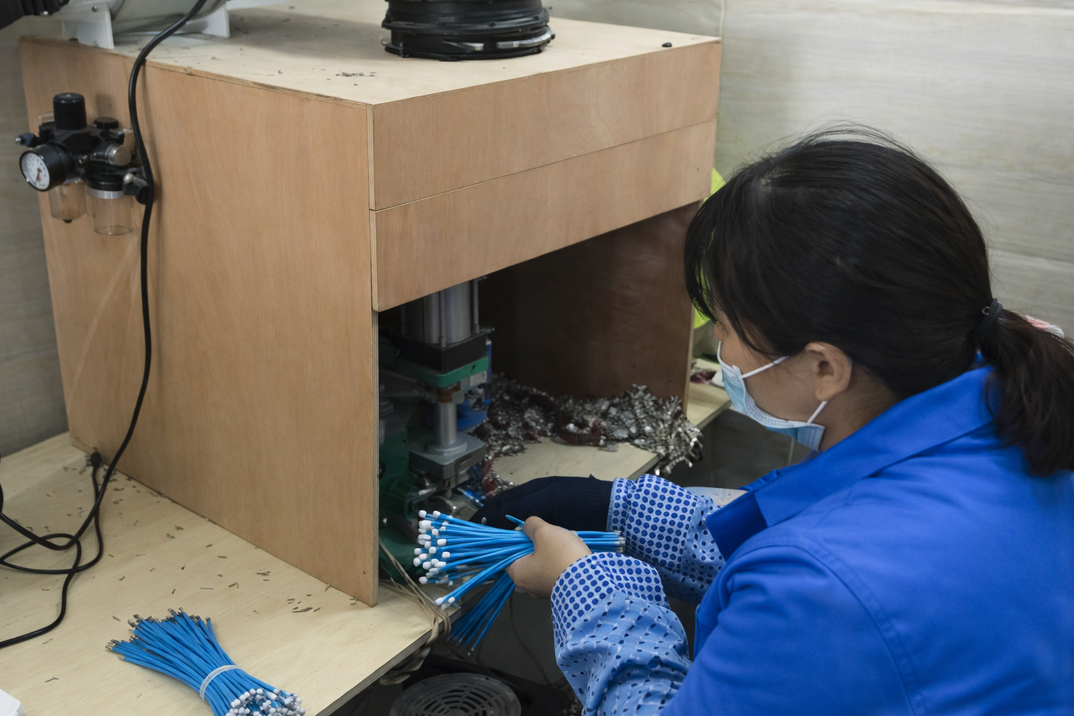
Cable cutting and stripping
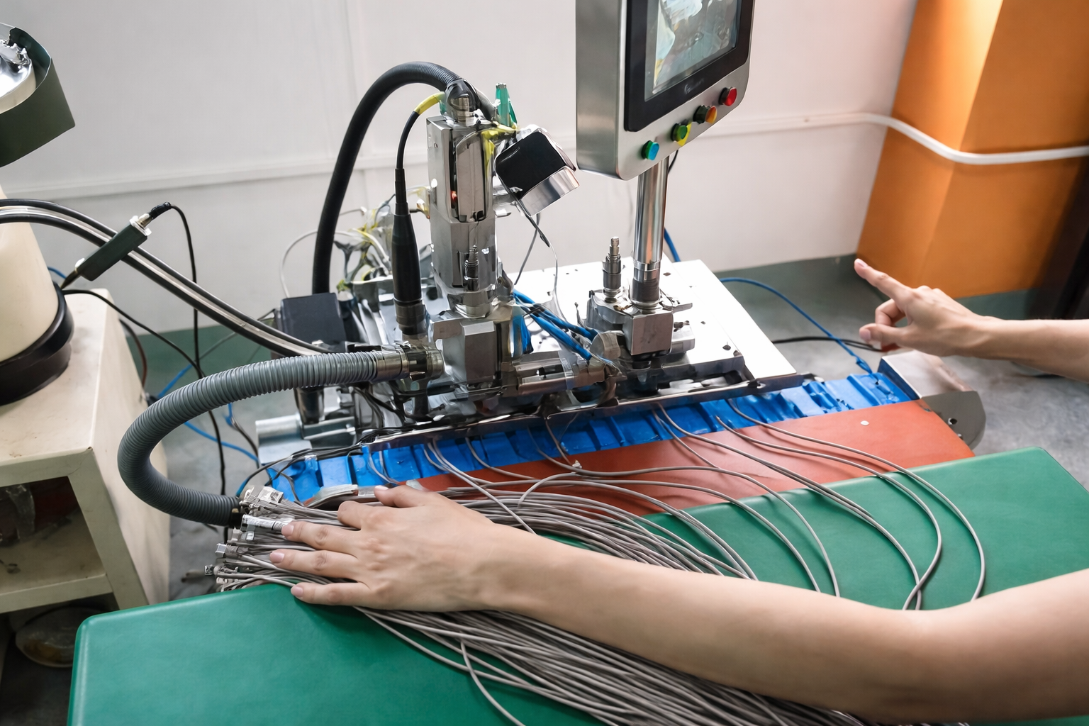
Terminal crimping or soldering

Injection Molding / Connector Assembly
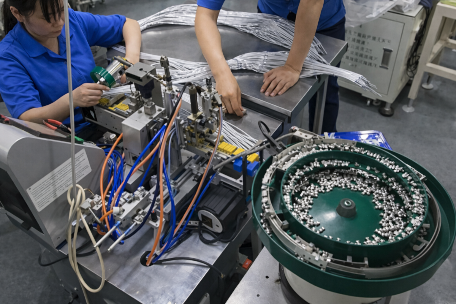
Connector assembly
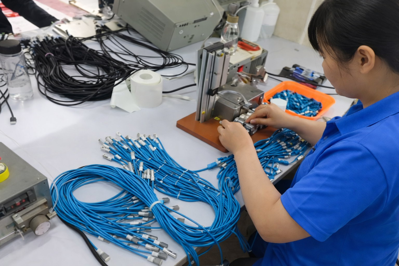
Sleeve, heat shrink or overmold processing
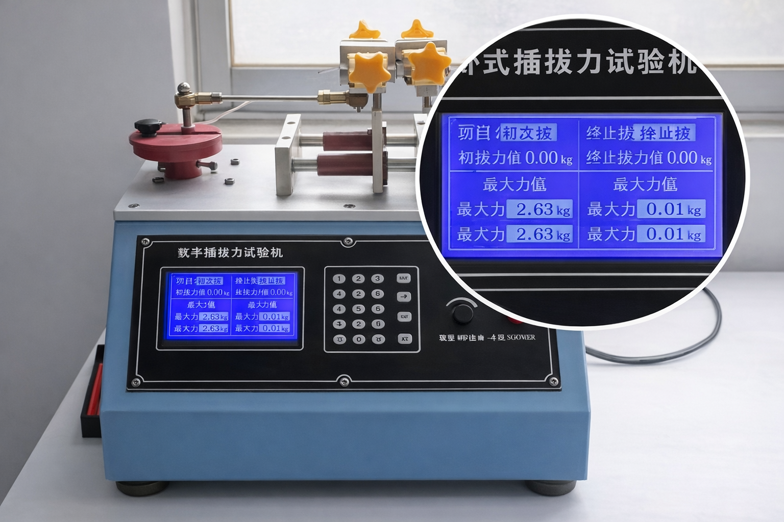
Continuity, polarity or fit check
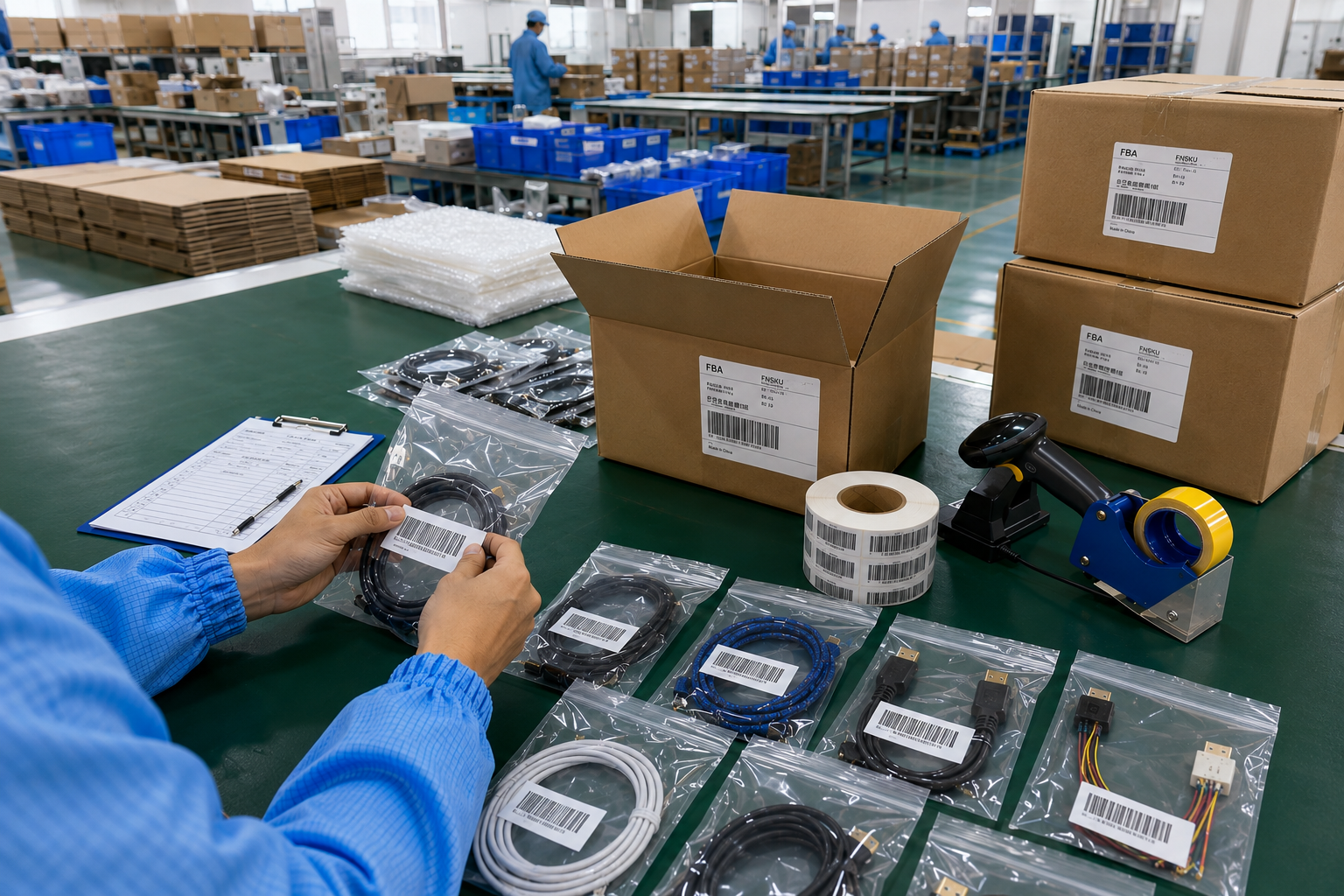
Appearance and label inspection

Packing, carton mark and shipment preparation
Project Files Protect Accuracy Across Revisions and Repeat Orders
File discipline reduces repeated clarification, outdated production instructions, wrong labels, and repeat-order errors. NDA requirements can be discussed before sensitive drawings, samples, device information, or development files are reviewed.
Drawing Control
Drawings define dimensions, connector direction, branch layout, labels, tolerances, overmold geometry, and other physical requirements. Each approved drawing should carry a revision number and date. Marked comments must be incorporated into the final file rather than left only in email threads. Production and inspection teams should work from the same approved revision. A changed drawing requires review against the BOM, pinout, sample, tooling, packaging, and existing material status.
BOM Control
The BOM connects every cable, connector, terminal, housing, sleeve, label, molded material, and packaging component to the assembly. Manufacturer part numbers, descriptions, quantities, alternatives, and approval status should be clear. Any component substitution should be reviewed before use. The final BOM should match the approved sample and drawing. Repeat orders should begin with a BOM comparison when suppliers, materials, connector availability, or design requirements have changed.
Pinout Control
Pinout files define circuit relationships that may not be visible from the finished assembly. Pin numbers, signal names, polarity, wire colors, AWG, shields, drain wires, jumps, and unused positions should use consistent naming. The approved pinout version must match testing instructions and connector orientation. Any engineering change should update both the pinout and relevant drawing or test file so production and quality teams do not follow different circuit definitions.
Sample Control
Approved samples should be identified by project, model, revision, and approval status. Photographs can support identification, but the physical sample remains valuable for appearance, handling, connector fit, mold shape, label position, and packaging comparison. Samples should connect to final drawings, BOM files, pinout, material requirements, and inspection criteria. A new revision should not automatically overwrite the previous reference until the update has been reviewed and approved.
Testing Control
Testing files identify which checks apply, how they are performed, acceptance criteria, sample size, reporting expectations, and equipment or fixture needs. Continuity, pinout, polarity, insulation, pull force, dimensions, fit, appearance, labels, packaging, or functional checks may be included according to the project. Updated circuit or mechanical specifications should trigger a testing-file review. Testing records should never rely on an outdated drawing or pinout version.
Packaging Control
Packaging files may include label artwork, model number, barcode, SKU, cable winding direction, bag or box type, protective components, packing quantity, carton mark, and packing-list information. Packaging revisions should remain linked to the correct cable revision. Multi-model or repeat-order programs need clear version names to prevent wrong labels or mixed cartons. Artwork and project files should not be displayed publicly without authorization.
Packaging and Identification Prepared for Controlled Project Delivery
Diagnostic equipment cable assemblies often require protection, clear model identification, controlled quantities, and accurate receiving information. Packaging should support engineering, assembly, warehouse, service, and supply-chain needs rather than focus only on visual presentation.

Cable Identification
Identification may use wire labels, heat-shrink markings, printed labels, model labels, circuit labels, connector-end labels, or orientation marks according to the assembly. Text, font, color, material, position, direction, adhesion, and revision should be confirmed before production. Labels must remain connected to the correct drawing and SKU. Inspection should verify content and placement against the approved artwork. Serialized or regulated identification requirements require separate project review and should not be assumed.

Protective Packing
Packing options may include cable winding, ties, protective bags, connector caps, dividers, trays, inner boxes, or other structures according to cable size, connector sensitivity, quantity, and shipping conditions. Packing should prevent unnecessary bending, connector impact, surface damage, tangling, or mixed models. The approved packing method should define quantity per bag or box, winding direction, protective components, and label position. Special packaging materials or environmental requirements need separate confirmation.

SKU and Carton Marks
Programs containing several connector types, lengths, branches, revisions, or device models require clear SKU separation. SKU labels, model labels, quantity labels, inner-box marks, and carton marks should use consistent names. The packing list must correspond with actual packed quantities and carton identification. Artwork, barcode data, carton dimensions, gross weight, and model breakdown should be confirmed before shipment preparation. Cablivo does not guarantee platform receiving or customs clearance outcomes.

Shipment Preparation
Shipment preparation may include final packing inspection, carton organization, packing list, carton size and weight data, shipping marks, finished-goods handling, and coordination with the nominated forwarder. Scheduling depends on production completion, outgoing inspection, packaging approval, carton preparation, and logistics arrangements. Export support does not replace importer responsibilities, customs review, or destination-country requirements. Final shipment information should be checked against the approved order and packing instructions.
MOQ, Cost, Sample Time, and Lead Time Factors
Commercial planning depends on the confirmed assembly specification. Connector sourcing, cable construction, tooling, verification, packaging, quantity, and revision status influence MOQ, cost, sample timing, and production scheduling.
Planning Area
Current Direction
Main Influencing Factors
Information Needed
MOQ
Starts from 500 pieces for many custom cable projects
Connector MOQ, cable structure, material, overmolding, tooling, packaging, SKU quantity
Target quantity and SKU breakdown
Prototype Quantity
Confirmed according to development needs
Number of versions, connector availability, tooling, testing, device fitting
Prototype plan and review requirements
Prototype Cost
Quoted after project review
Connectors, materials, cable construction, labor, tooling, tests, packaging
Drawing, BOM, samples, and test list
Unit Cost
Based on final specification and quantity
AWG, length, connector, terminal, shielding, jacket, branches, overmolding, labels
Final specification and quantity
Tooling Cost
Applies when custom tooling is required
Mold shape, connector positioning, size, surface, logo, material, revision risk
Drawing, 3D file, sample, or marked photos
Sample Time
Confirmed after technical review
Product structure, connector availability, material preparation, tooling, testing
Complete available engineering files
Production Lead Time
Confirmed after sample approval and order review
Materials, connectors, tooling, order quantity, process, testing, packaging
Approved files and confirmed order
Packaging Cost
Based on approved packing plan
Bag, box, tray, divider, labels, barcode, carton, packing quantity
Packaging artwork and packing instructions
Revision Impact
Reviewed before implementation
Material already purchased, tooling status, sample stage, production progress
Written revision list and updated files
Repeat Orders
Reviewed against the previous approved version
Component changes, availability, artwork, quantity, test updates
Previous order details and revision summary
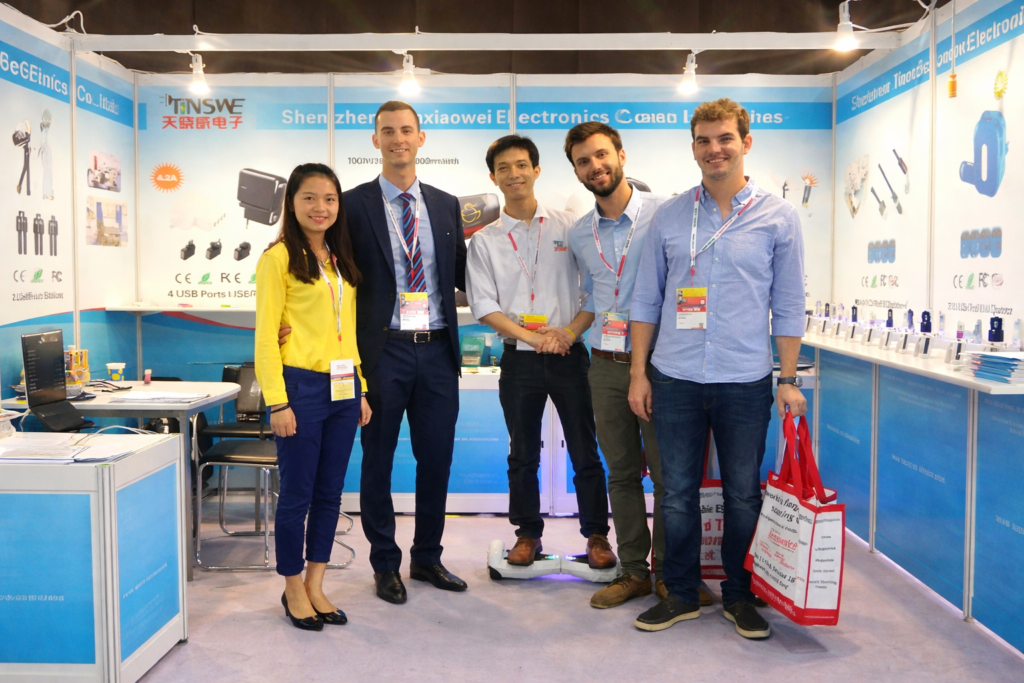
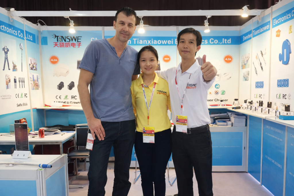
Why Customers Trust Tianxiaowei
Real customer feedback and cooperation moments that reflect our product quality, responsive service, and
long-term manufacturing support.
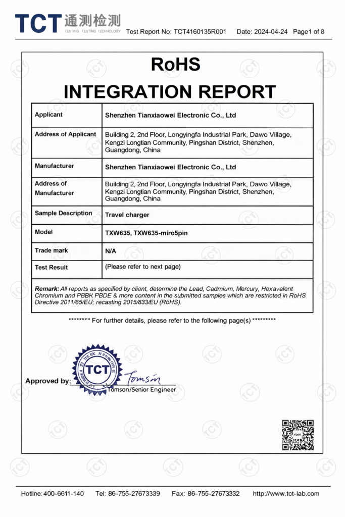
Certificates & material control
Diagnostic Cable Frequently Asked Questions
The answers below cover engineering review, prototype development, testing, production, MOQ, documentation, and confidentiality for diagnostic device cable assembly programs.
What files are needed for engineering review?
Available drawings, BOM files, connector datasheets, pinout tables, sample photographs, interface photographs, cable lengths, AWG requirements, quantities, testing requirements, and packaging information are helpful. Complete files are not required for an initial discussion. Cablivo can review current information and identify missing decisions before quotation or sampling.
Can Cablivo work from an existing cable sample?
Yes. Clear photographs or a physical sample can support connector, length, branch, material, label, and structure review. A sample alone may not reveal conductor size, pinout, internal construction, approved materials, or test requirements. Additional confirmation may be required before replication, modification, or production.
How are connectors and pinout confirmed?
Connector confirmation may use model numbers, datasheets, mating interfaces, photographs, or physical samples. Pinout should be defined through a pinout table, wiring diagram, approved old sample, or device specification. Mechanical fit and electrical wiring are reviewed separately before prototype approval.
Can cable materials be selected by application?
Material direction can be discussed according to flexibility, routing, diameter, appearance, movement, protection, cleaning conditions, cost, processing, availability, and target-market requirements. Final selection should be confirmed through project specifications, material information, prototype evaluation, and relevant testing needs.
Can Cablivo support prototype revisions?
Sample feedback can be reviewed, and revision direction can be discussed before a revised sample is produced. Engineering groups should provide measurable comments, updated drawings, photographs, or marked files. Revision cost and timing may change according to materials, connectors, tooling, tests, and project stage.
How are testing requirements confirmed?
Testing depends on cable function, structure, device application, internal standards, and target-market needs. Possible checks include continuity, pinout, polarity, connector fit, dimensions, pull force, insulation, appearance, labels, packaging, and outgoing inspection. Acceptance criteria should be supplied or agreed before production.
How is an approved sample transferred into production?
The approved sample is linked with the final drawing, BOM, connector list, pinout, material direction, overmold information, label artwork, packaging files, inspection checklist, and revision number. Production preparation and outgoing inspection use the confirmed reference set.
Can overmolding and strain relief be customized?
Overmold shape, connector exposure, cable exit, strain relief, dimensions, surface, color, and logo position can be discussed according to the project. Custom tooling may be required. Feasibility, cost, and sample timing are confirmed after reviewing the connector, cable, drawing, sample, and production quantity.
What is the MOQ for custom cable assemblies?
MOQ starts from 500 pieces for many custom cable projects. Final MOQ depends on connector type, cable structure, materials, overmolding, tooling, packaging, SKU quantity, and total order volume. Submit the quantity per configuration for a more accurate review.
Can NDA and documentation requirements be discussed?
Yes. NDA needs can be discussed before reviewing sensitive drawings, BOM files, device information, samples, or packaging artwork. Material documents, third-party testing, reports, and target-market requirements should be listed during project review. Availability depends on the product, material source, requested standard, and confirmed scope.
Send Your Diagnostic Device Cable Assembly Requirements
Share the engineering information currently available, even when several specifications remain open. Cablivo can begin with a drawing, BOM, connector datasheet, pinout table, existing sample, interface photograph, application description, or preliminary quantity.
The first review focuses on understanding the device connection, identifying missing information, and confirming which details affect connector selection, cable structure, prototype development, tooling, testing, MOQ, cost, packaging, and production planning. Files do not need to be perfectly organized before the initial submission.
For a more accurate evaluation, include the assembly application, connector model, cable length, AWG, pinout, material direction, expected quantity, prototype requirements, target delivery plan, inspection needs, and packaging instructions whenever available.
NDA requirements can be discussed before confidential project information is reviewed. Sample and production timing will be confirmed after the product structure, connector availability, materials, tooling, testing, packaging, and order details have been assessed.