...

Custom USB Cable Manufacturer

USB cable development for global brands, engineering teams, procurement teams, device makers, distributors and long-term supply programs.

Cablivo supports USB cable programs from early specification review through prototype approval, production control, functional checks, branded packing and shipment coordination.

  • USB-C, USB-A, Micro USB, extension, panel-mount, molded and device-specific assemblies
  • Drawing, BOM, sample, connector, pinout, length, AWG and application review
  • Prototype feedback, approved-sample control and production-file confirmation
  • Charging, data, fit, appearance, label and packing checks arranged by project scope
  • MOQ starts from 500 pcs for many custom cable programs; final MOQ follows structure, tooling and packing requirements

USB Manufacturing Capabilities at a Glance

Six capability areas help project teams evaluate product fit, development depth, production control, inspection planning and channel-ready delivery before sending an RFQ.

Broad USB Range

USB programs may involve USB-C, USB-A, Micro USB, extension leads, panel-mount assemblies, open-end leads, device-specific connectors, molded plugs and private-label charging or data cables. Product selection starts with interface, application and function rather than a generic catalog match. The final configuration is confirmed through drawings, samples, interface photos or written specifications.

Engineering Review

Project files are reviewed before sampling. Typical inputs include drawings, BOMs, pinout tables, connector models, old samples, device-interface photos, cable length, wire gauge, target quantity and test requirements. Missing details are listed for confirmation, allowing engineering and procurement teams to align the specification before tooling, material preparation or prototype work begins.

Prototype Control

Prototype work converts an approved specification into a physical sample for interface, function, length, material, color, overmold, strain-relief, label and packing review. Feedback is recorded before a revised sample is arranged. Sample timing is quoted after structure, connector availability, material preparation, tooling and test needs have been reviewed.

Production Readiness

Bulk production begins after the approved sample, final drawing, final BOM, labeling files, packaging artwork, test plan and SKU information are confirmed. Incoming inspection, process checks and outgoing inspection are linked to the locked production files. Material or connector substitutions are reviewed before use whenever appearance, function, testing, cost or schedule may be affected.

Project-Based Testing

Inspection is selected around the required function and application. Common directions include continuity, pinout or polarity, charging function, data function, connector fit, dimensions, pull-force discussion, bending discussion, appearance, label accuracy, barcode accuracy and packing inspection. Test methods and acceptance criteria are confirmed before sampling or mass production.

Brand Delivery Support

Private-label programs can include logo placement, color direction, retail box, poly bag, insert card, barcode, SKU label, carton mark, multi-length variants and multi-interface variants. Artwork and label content are supplied or approved by the brand team before packing production. Export documentation and forwarder coordination are handled according to confirmed order details.

Custom USB Cable Product Range

A structured product matrix helps brands and equipment teams identify the nearest USB cable direction before connector, function, size, material, testing and packing details are reviewed.

USB-C to USB-C

Suitable for modern charging, data and device-connection programs where both ends use USB-C. RFQ files should state target equipment, cable length, intended charging or data function, connector shell direction, outer-jacket preference, color, logo, packaging and any certification target. Power or data capability is not assumed from the connector shape alone; required performance must be defined and validated for the final construction.

USB-A to USB-C

Used for accessories, power adapters, computers, charging products and equipment interfaces combining a USB-A host side with a USB-C device side. Development focuses on connector construction, conductor layout, length, flexibility, strain relief, charging or data requirements and channel presentation. Brand programs may add custom colors, logo marks, retail packaging, barcode labels and multiple length options under one SKU family.

USB-A to Micro USB

A mature interface combination used in legacy accessories, control devices, instruments and replacement programs. A reliable quotation needs connector orientation, cable length, conductor requirement, expected function, device fit, overmold shape, color, labeling and quantity. Existing samples can be reviewed when drawings are incomplete, while final dimensions and wiring details are confirmed before prototype work.

USB-C to Micro USB

Useful when a USB-C source or host must connect with equipment retaining a Micro USB interface. Interface photos, mating-device information, function definition and cable length help prevent connector-orientation or fit errors. The cable can be developed with straight or angled exits, molded protection, selected jacket materials, custom color, logo and packing according to the sales channel or equipment program.

USB Extension Cable

Extension assemblies may use USB-A or USB-C connectors and can include standard, panel-mount or device-specific structures. Length, male or female orientation, mounting method, data or power requirement, shielding discussion and installation space should be reviewed before design confirmation. Longer constructions require additional attention to function, conductor choice and test planning rather than a simple length change.

Panel-Mount USB Cable

Panel-mount designs support equipment enclosures, cabinets, kiosks, control panels and integrated products. Important inputs include cutout dimensions, screw or snap-in mounting, panel thickness, connector orientation, rear cable exit, internal mating connector, cable length and environment. Mechanical fit is confirmed with drawings or panel details before sampling, while labels and branch identification can be added for assembly-line use.

USB to Open End

Open-end USB leads allow the opposite side to connect directly with a PCB, terminal, solder point or internal device assembly. Pinout, conductor colors, stripping length, tinning, terminal treatment, wire gauge and branch identification must be defined. Such programs suit equipment integration, repair kits and internal assembly when a standard second connector is not required.

USB Device Assembly

Device-specific assemblies combine a USB connector with a proprietary, circular, DC, terminal or board-side interface. Development begins with connector models, mating details, pinout, voltage or current requirements, data function, cable routing, overmold and installation space. A sample or interface photo can start the review when a complete drawing is not yet available.

Molded USB Cable

Injection molding can create a repeatable connector body, logo position, strain relief and exterior geometry around the plug area. Mold dimensions, cable diameter, connector shell, exit angle, surface finish, color and marking requirements are reviewed before tooling. Prototype approval is used to confirm fit and appearance before the final production file is released.

Braided USB Cable

Braided constructions support a distinct visual identity and added surface protection for accessory brands and retail programs. Sleeve material, weave appearance, diameter, flexibility, color matching, connector transition, overmold shape and packing volume should be considered together. A material or color sample may be used before full cable sampling when appearance is central to the product line.

USB Charging Cable

Charging-focused programs require more than a connector combination. The target device, power source, cable length, wire gauge, component plan and test requirement should be stated before quotation. Logo, color, multi-connector structures and retail packaging can be added after the electrical and mechanical direction is clear. Performance claims are tied to the approved construction and validation plan.

USB Data Cable

Data-focused programs start with the intended device, protocol target, cable length, shielding discussion, conductor structure, connector design and verification method. A broad phrase such as high-speed cable is not enough for engineering release. The required data function is documented, samples are checked against the agreed method, and production inspection follows the approved specification.

USB Cable Programs for Different Project Teams

Different project roles evaluate a manufacturer through different evidence. Product development, procurement, equipment integration, distribution and repeat supply each require a distinct information path.

Electronics Brands

Electronics and accessory brands usually require a coordinated product family rather than one isolated cable. Interface combinations, lengths, colors, logo placement, retail packaging, barcode files and carton marks need a common approval path. Prototype appearance and function are reviewed before bulk release, while production files help preserve consistency across repeat orders and future SKU extensions. The main value lies in linking manufacturing with brand presentation and version control.

Engineering Teams

Engineering teams focus on connector fit, pinout, electrical function, cable routing, overmold geometry, device integration and test criteria. A useful manufacturing partner must read drawings, BOMs, pinout tables and interface data, then identify open points before sampling. When full drawings are unavailable, sample photos, connector images, cable length, application notes and target quantity can support an initial review. Formal approval follows once the specification is complete.

Procurement Teams

Procurement teams compare more than unit price. MOQ, material selection, connector sourcing, tooling, sample timing, production schedule, inspection planning, packaging cost and shipment terms all influence supplier risk. Cablivo provides a structured RFQ path so commercial and technical inputs can be reviewed together. MOQ starts from 500 pcs for many custom cable programs, while final quantity requirements depend on construction and packing.

Device Manufacturers

Device manufacturers often need USB leads designed around enclosure dimensions, panel cutouts, internal connectors, routing space, assembly direction and field use. Panel-mount cables, open-end leads and USB-to-device assemblies may require custom stripping, terminals, labels or molded protection. Fit and function are validated with drawings, interface photos, mating parts or samples before production files are locked.

Importers Distributors

Importers and distributors manage multiple lengths, connector combinations, colors and packing versions. Clear SKU lists, barcode files, carton quantities, carton marks and model references reduce warehouse and reorder errors. Product, label and packaging checks are planned by SKU before shipment. Export packing, invoice, packing-list and forwarder coordination can be discussed according to destination, shipment size and delivery plan.

Long-Term Programs

Long-term supply programs require stable drawings, approved samples, BOM control, replacement review, inspection checkpoints, packing files and repeat-order version management. New material or connector proposals are discussed before use when function, appearance, testing, cost or schedule could change. The program can grow from an initial product or trial quantity into additional lengths, colors, interfaces or markets after the first construction is approved.

What Strong USB Supply Programs Require

A reliable USB cable program aligns interface, function, dimensions, materials, prototypes, production files, inspection and delivery planning before a bulk order is released.

Interface Accuracy

Connector family, male or female orientation, plug direction, mating part, shell dimensions and exit direction must match the intended product. A connector photo alone may not identify every internal detail, so model numbers, datasheets or samples are preferred. Interface accuracy supports device fit, tooling decisions, assembly direction and later replacement control.

Defined Function

Charging, data, device recognition and power-only use need separate definitions. The same connector shape can support different functions depending on cable construction and components. Project files should identify target devices, source equipment, required protocol or charging objective and any acceptance method. Function is then checked on the agreed sample and production configuration.

Controlled Dimensions

Finished cable length, tolerance, overmold size, connector body size, panel-mount dimensions, stripping length and branch dimensions affect installation, packing and SKU management. Common RFQ length entries may be expressed in millimeters, centimeters, meters, inches or feet, but one unit system should be fixed in the final drawing. Dimensional checkpoints follow the approved specification.

Material Fit

Conductor, insulation, shielding, jacket, sleeve, connector shell, overmold material and packaging components are selected around function, flexibility, appearance, target channel, cost and test needs. A material choice suitable for one accessory may not fit an industrial or panel-mount application. Final selections are listed in the BOM before production.

Prototype Evidence

A prototype should answer defined questions: Does the connector fit? Is the pinout correct? Does the cable perform the required charging or data function? Are length, flexibility, color, overmold and logo acceptable? Is the proposed packaging suitable? Clear approval criteria help reduce repeated sample changes and create a stronger reference for mass production.

Production Files

Approved samples alone are not enough for repeatable production. Final drawings, BOMs, pinout tables, label files, packaging artwork, barcode lists, SKU lists and test requirements must support the physical sample. Version numbers and approval dates help prevent production from relying on scattered email messages or outdated files.

Inspection Plan

Inspection should cover the risks attached to the final construction. Incoming material checks, in-process inspection, continuity, pinout, function, fit, dimensions, appearance, labels, barcode, packing quantity and carton marks may be included. The exact plan is confirmed by product type, application and project requirements rather than applying one generic checklist to every USB cable.

Delivery Planning

Production scheduling depends on product structure, material availability, connector sourcing, tooling, order quantity, test plan and packaging. A realistic schedule is confirmed after sample approval and final order details are complete. Destination, preferred shipping method, forwarder arrangement, carton data and required export documents should be supplied early enough for shipment coordination.

Common USB Cable Risks and Control Actions

Early risk review protects engineering schedules, brand presentation and repeat-order consistency. Each issue below links a common failure mode with a clear prevention action.

Connector Mismatch

Risk: a visually similar connector may differ in orientation, shell size, internal contact arrangement or mating fit. Consequences include assembly failure, device damage, sample delay and replacement cost. Review action: provide connector model, datasheet, mating-part details, device-interface images or an old sample. Fit and orientation are checked before tooling or production release.

Unclear Function

Risk: terms such as fast charge, data cable or USB-C can hide missing electrical details. Consequences include charging complaints, device recognition problems or failed internal validation. Review action: define the source, target device, intended function, cable length, component requirement and acceptance method. A sample is then evaluated against the agreed specification.

Pinout Error

Risk: wiring or polarity errors can stop charging, data transfer or device operation. Consequences include unusable samples, engineering rework and bulk-order exposure. Review action: submit a pinout table, wiring diagram, color definition or verified sample. The final pinout is linked to the drawing and functional check before mass production.

Sample Bulk Gap

Risk: production differs from the approved sample because files, materials, labels or packaging were not locked. Consequences include appearance variation, function changes, mixed versions and repeat-order disputes. Review action: confirm approved sample, final drawing, BOM, color reference, logo file, test plan, SKU list and packaging artwork before scheduling.

Material Substitution

Risk: an unapproved material, connector or packaging change affects flexibility, appearance, function, testing, cost or lead time. Consequences include validation failure and brand inconsistency. Review action: substitution reasons and impacts are reviewed before use. Re-sampling is discussed when the proposed change alters a critical characteristic.

SKU Packing Error

Risk: multiple lengths, colors, interfaces or markets are packed under the wrong barcode, label or carton mark. Consequences include warehouse confusion, channel returns and delayed launches. Review action: provide a SKU matrix with product code, length, color, interface, quantity, barcode, packaging version and carton information. OQC checks are arranged around the approved list.

Nine USB Cable Customization Areas

Custom development covers electrical, mechanical and channel requirements. Each choice should connect with the intended device, brand position, production plan and verification method.

Connector Combination

Select USB-C, USB-A, Micro USB, extension, panel-mount, open-end or a device-side connector. State male or female orientation, plug direction, mating part and any angle requirement. Connector availability and mechanical fit are checked before sampling.

Cable Length

Provide finished length, tolerance and measurement points. Multi-SKU programs should list every length separately. Length affects installation, packing, conductor selection, function and shipping volume, so final dimensions are fixed in the drawing.

Wire Gauge AWG

Wire gauge is reviewed around current requirement, cable length, connector type, flexibility, outside diameter and installation space. A generic AWG recommendation is avoided until electrical and mechanical inputs are complete.

Conductor Design

Conductor material, strand construction, core count and layout are selected around function and flexibility. Copper or tinned-copper directions can be discussed, while final construction follows the required charging, data or device-connection objective.

Insulation Shielding

Insulation separates conductors and supports structural stability. Foil or braided shielding may be discussed for data, signal or equipment applications where needed. Shielding is not added automatically; function and test requirements guide the decision.

Jacket Sleeve

PVC, TPE, TPU, PUR, silicone and sleeve directions may be evaluated for appearance, feel, flexibility, cost, channel presentation and application. Material compliance follows actual material documents and the target market requirement.

Overmold Strain Relief

Overmold shape, dimensions, exit direction, logo area, surface finish and strain-relief geometry can be developed around the connector and cable diameter. Tooling requirements are confirmed before a molded sample is produced.

Color Logo Label

Custom color, logo position, model number, wire label, SKU label and barcode can support brand identity and warehouse control. Artwork, color reference and label content must be supplied or approved before production.

Retail Export Packing

Bulk packing, poly bags, OPP bags, retail boxes, color boxes, insert cards, multi-SKU packing and export cartons can be discussed. Packing selection affects MOQ, cost, lead time, carton size and shipping volume.

USB Connector and Interface Options

Clear interface definition prevents fit, orientation and sourcing errors. Product images, connector datasheets, mating details and device photos provide a stronger starting point than connector names alone.

USB-C Plug

Specify plug direction, shell style, cable exit, overmold shape and target function. USB-C appearance alone does not define charging or data capability. Required performance, component plan, length and test method are reviewed before sample approval. Device and source details improve fit and functional evaluation.

USB-A Plug

USB-A plugs remain common for adapters, computers, hubs and equipment. Confirm host-side use, plug orientation, shell dimensions, cable exit, length, charging or data function and any logo area. The connector can pair with USB-C, Micro USB, a device connector or an open-end termination.

Micro USB Plug

Micro USB is still used in legacy electronics, instruments and equipment. State orientation, mating device, cable exit, length, function and overmold requirement. Interface photos and an existing sample help identify fit details when a full drawing is unavailable.

Extension Interface

Male-to-female extension structures need connector orientation, mounting arrangement, finished length, data or power requirement, shielding discussion and installation details. Longer lengths require a function review rather than a simple dimensional change.

Panel Mount

Panel-mount designs require cutout dimensions, panel thickness, fixing method, front and rear orientation, cable exit, internal connector and available space. Mechanical drawings or enclosure details are important before prototype construction.

Open End

Open-end terminations may include stripped conductors, tinned ends, terminals, housings or direct solder preparation. Pinout, core colors, stripping length, wire gauge and assembly method must be defined in the production drawing.

Straight Angle Exit

Straight, right-angle or custom exit directions affect equipment clearance, strain relief, packaging and tooling. Connector orientation and cable-bend direction are reviewed with the device layout before mold design or sample release.

Custom Device End

The non-USB side can use a DC plug, circular connector, terminal housing, board connector or another defined interface. Supply the connector model, mating data, pinout, application and installation space. Connector sourcing and tooling are confirmed before quotation is finalized.

Define Charging, Data and Device Requirements

A connector name does not define the finished function. The matrix below converts broad requests into engineering inputs, review actions and release evidence.

Requirement Area

Information to Provide

Review Direction

Release Evidence

Charging Function

Source, target device, required power objective, cable length

Conductor, connector, component and heat-risk discussion

Approved sample and agreed functional check

Data Function

Target device, protocol objective, length, shielding or structure needs

Cable construction and verification-method review

Sample result linked to final specification

Power Only

Voltage, current, polarity if applicable, device use

Core layout, gauge and connector discussion

Continuity or polarity check as defined

Device Fit

Mating interface, enclosure image, panel or clearance dimensions

Connector orientation, shell and exit-direction review

Fit confirmation using sample or mating part

Dimensions

Finished length, tolerance, overmold size, panel cutout, strip length

Drawing and measurement-point confirmation

Approved dimensional drawing

E-Marker / PD

Target requirement and product scope

Component, construction and certification-route review

Product-specific evidence when required

Mechanical Needs

Pull, bend, insertion, routing or installation concern

Test method and acceptance criteria discussion

Agreed sample or production test plan

Packaging

SKU list, barcode, artwork, carton mark, quantity per pack

Version and packing-file review

Approved packing sample or packing specification

USB Cable Materials and Structure

Material and structure choices shape function, flexibility, connector fit, appearance, packing and production consistency. Every layer should support a defined product requirement.

Build the Cable from the Inside Out

A custom USB cable starts with conductor layout, core count, insulation and any shielding requirement. Wire gauge affects current capability, outside diameter, flexibility, connector fit, heat risk and cost. Insulation supports conductor separation and structural stability. Foil or braided shielding may be discussed for data or equipment applications, but shielding is selected only when the required function and verification plan justify it. Engineering inputs should include intended charging or data use, cable length, device, connector type, installation space and target test conditions. The final cross-section belongs in the drawing or BOM, preventing production from relying on a generic cable description.

Select the Jacket for Use and Brand Position

The outer jacket influences flexibility, hand feel, appearance, packing volume and application fit. PVC, TPE, TPU, PUR and silicone directions may be reviewed according to cost, flexibility, surface feel, target market, channel position and test needs. A premium retail accessory may prioritize color and tactile feel, while an equipment lead may prioritize routing, label visibility and assembly convenience. Material claims are based on actual supplier documents and confirmed test requirements. Unverified temperature, flame, medical, automotive or environmental claims are avoided. Color references and surface expectations should be approved before mass production.

Engineer the Connector Transition

The transition from cable to connector combines shell fit, soldering or terminal connection, shielding termination, overmold geometry and strain relief. Straight or angled exits must match the equipment layout and packing plan. Overmold size, logo position, surface finish, color, cable diameter and tool-parting direction are reviewed before tooling. A molded sample provides evidence for connector fit, cable exit, appearance and dimensional approval. When the connector, material or mold proposal changes after approval, the functional, visual, cost and schedule impact is reviewed before use.

Engineering Review before USB Cable Sampling

Drawing, BOM, connector, pinout and application review converts incomplete ideas into a clear sample specification and a stronger production baseline.

Start with the Best Available Project Evidence

A complete drawing is ideal, yet early review can begin with an old sample, connector photos, interface images, BOM, pinout table, cable length, application notes and target quantity. The available evidence is organized into product, engineering, commercial, test and packaging inputs. Open questions are returned in a structured list rather than hidden until sampling. For replacement programs, visible issues such as connector fit, jacket feel, strain-relief shape, label position or packing errors can also be recorded. NDA discussion is available for brand, engineering and new-product programs when project confidentiality needs to be addressed.

Confirm the Specification before Prototype Work

Engineering review covers connector model, mating part, male or female orientation, pinout, wire sequence, cable length, tolerance, wire gauge, conductor structure, insulation, shielding, jacket, overmold, logo, label and test requirement. Tooling is discussed when a custom molded body or panel-mount feature is needed. Connector availability is checked before the final quotation or sample schedule is released. A concise specification summary becomes the working reference for prototype construction, reducing misunderstandings between procurement, engineering, production and packaging teams.

Release Production Files after Sample Approval

Sample approval should be supported by a final drawing, final BOM, pinout or wiring table, color reference, logo file, label file, SKU list, packaging artwork and test requirement. Version numbers and approval dates help distinguish current files from earlier revisions. Material, connector or packaging changes are not treated as informal production decisions when function, appearance, cost, testing or schedule may be affected. The approved sample and final files together create a repeatable production baseline for the first bulk order and later reorders.

USB Cable Prototype Development Process

A six-stage process turns engineering inputs into a verified sample, records revisions and creates the files needed for repeatable production.

Requirement Review

Available drawings, samples, connector images, pinout, cable length, AWG, application, quantity, testing and packing information are reviewed. Missing items are summarized so the next decision is clear. Early review can begin before every file is complete, yet sample release waits until critical interface and function details are confirmed.

Material Confirmation

Connector model, conductor, insulation, shielding, jacket, sleeve, overmold and packaging materials are discussed around function, appearance and availability. Tooling is identified when a custom molded shape is required. Material or connector options are compared before prototype preparation rather than changed during bulk production.

Prototype Build

The agreed sample specification moves into material preparation, cable processing, connector assembly, molding, labeling and functional checks. Sample timing is confirmed after product structure, connector availability, material preparation, tooling and testing needs are known. Complex molded or multi-connector constructions generally require more preparation than standard open-tooling assemblies.

Function Fit Check

The prototype is reviewed for connector fit, pinout, charging or data function, finished length, dimensions, flexibility, appearance, overmold, logo and labels according to the project scope. A mating device, interface sample or defined test method may be needed for reliable confirmation. Broad performance claims are replaced with agreed verification steps.

Feedback Revision

Feedback is recorded by item: function, fit, dimension, material, color, logo, molding, label or packaging. Revision direction, cost impact and timing impact are confirmed before a revised sample is arranged. Unlimited or free revisions are not assumed; the objective is a controlled route toward a production-ready sample.

Sample Approval

Approval identifies the physical sample and supporting files used for bulk production. Final drawing, BOM, pinout, color reference, logo, label, SKU list, packing artwork and test plan are checked for alignment. Sample approval reduces mass-production risk only when production files are complete and current.

Production Process for Power Cable Assemblies

Power cable production may include cutting, stripping, crimping, soldering, overmolding, assembly, testing, labeling and packaging, depending on cable structure.

Typical production flow:

Material and connector preparation
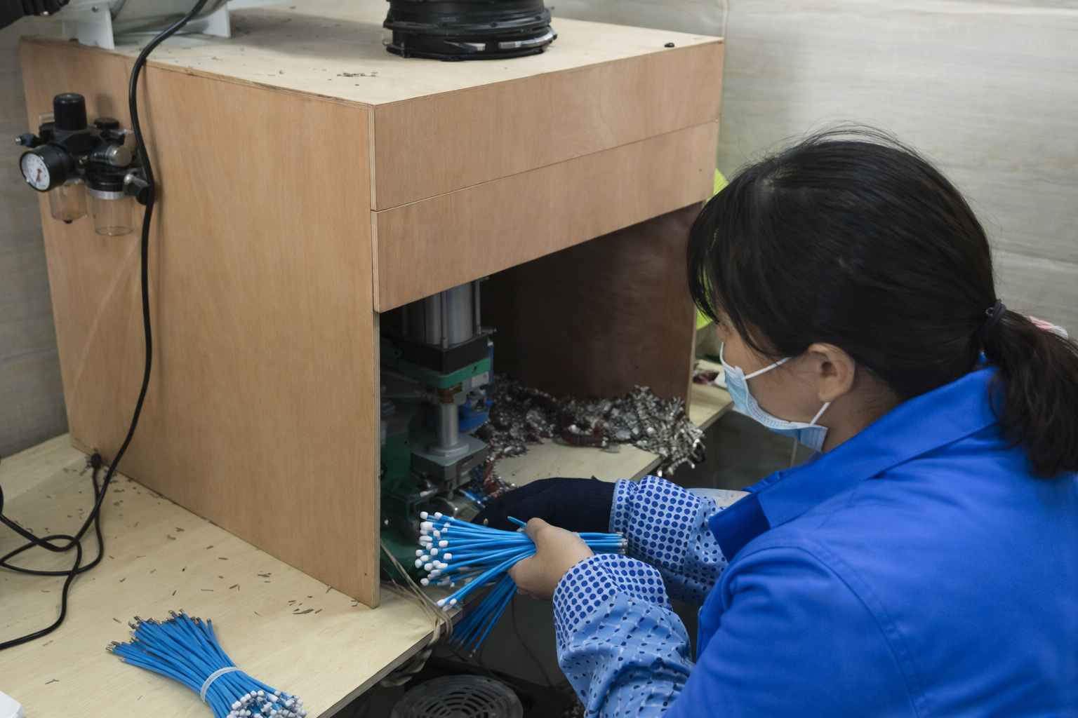
Cable cutting and stripping
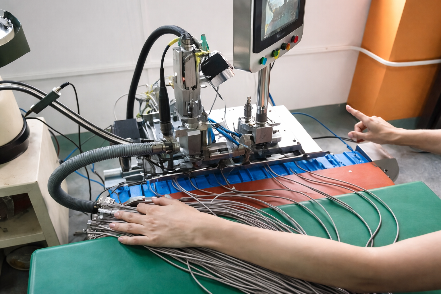
Terminal crimping or soldering

Injection Molding / Connector Assembly
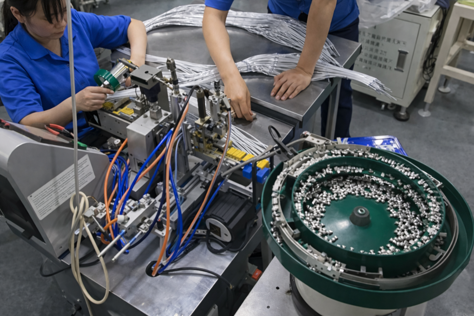
Connector assembly
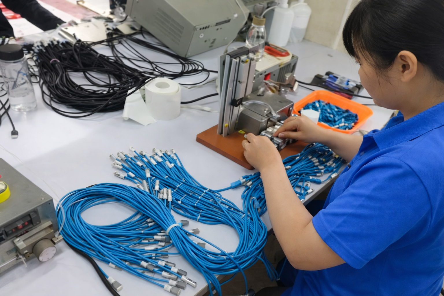
Sleeve, heat shrink or overmold processing

Continuity, polarity or fit check
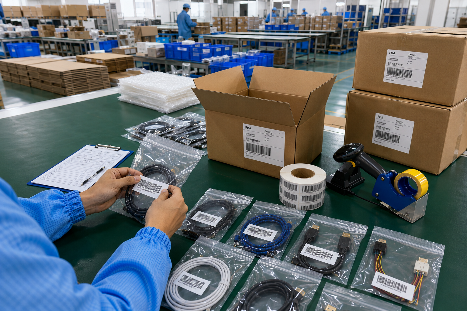
Appearance and label inspection

Packing, carton mark and shipment preparation

From Approved Sample to Repeatable Production

Sample-to-production consistency depends on six linked controls: physical approval, dimensional files, material files, brand files, inspection checkpoints and reorder version management.

Approved Sample

The approved physical sample provides a reference for fit, function, dimensions, flexibility, color, molding, logo, label and packing appearance. It must be identified clearly and linked to the released files. A sample without matching documentation cannot fully protect repeat-order consistency.

Final Drawing

The drawing records connector combination, orientation, cable length, tolerances, overmold dimensions, panel details, stripping length and other measurable features. One measurement unit should be used consistently. Revision control prevents an earlier drawing from returning to production during future orders.

Final BOM

The BOM identifies wire construction, connector, terminal, shell, insulation, shielding, jacket, sleeve, molding material, label and packing components. Approved alternatives are recorded rather than selected informally. Material availability and any proposed replacement are reviewed before production.

Locked Brand Files

Logo artwork, color reference, model number, barcode, SKU label, insert card, retail-box artwork and carton mark are approved before packing materials are produced. Multi-market or multi-SKU programs should separate every version in a clear matrix.

Quality Checkpoints

Incoming inspection, process checks, functional checks, dimensional checks, appearance review, label verification, packing inspection and OQC are aligned with the product risks. The exact checklist follows the final construction and agreed acceptance criteria.

Repeat Order Control

Reorders should reference the approved sample, drawing revision, BOM revision, SKU list and packing version. Material or connector changes are reviewed before use, and re-sampling is discussed when a change may affect function, fit, appearance or validation. File discipline supports expansion into new lengths, colors or interfaces.

Quality Checks for Custom USB Cable Programs

Quality control is built around the approved construction and risk profile, from incoming materials through function, dimensions, appearance, labeling and final packing.

Incoming Inspection

Incoming checks may cover wire, connectors, terminals, shells, jackets, sleeves, molding materials, labels and packing components. The objective is to reduce the chance of incorrect or visibly inconsistent materials entering production. Inspection depth follows material risk and project requirements.

Continuity Pinout

Continuity confirms circuit connection, while pinout or polarity checks compare wiring with the approved table. Open-end leads, device assemblies and multi-core constructions need especially clear wiring information. Test references are linked to the final drawing or pinout file.

Charging Function

Charging checks require a defined source, target device, cable configuration and objective. Connector type alone does not establish capability. The accepted method and any required fixture are confirmed before sampling or production inspection.

Data Function

Data checks depend on the intended device, protocol objective, cable length, construction and verification method. A generic high-speed label is avoided unless the product-specific construction and evidence support it. The final requirement belongs in the specification.

Fit Dimensions

Connector mating, panel fit, overmold dimensions, finished cable length, strip length and branch dimensions may be checked against drawings, samples or mating parts. Measurement points and tolerances must be clear before production begins.

Mechanical Discussion

Pull-force, bending, swing, insertion or connector-life testing may be discussed when the application requires it. Test method, sample quantity, acceptance criteria and whether third-party work is needed should be defined before the test plan is released.

Appearance Label

Appearance review can cover connector molding, cable surface, color, logo, printing, label position, model number, barcode and SKU match. Approved color references and artwork prevent subjective expectations from appearing only after production.

Packing OQC

Packing inspection may verify bag or box type, insert card, barcode, SKU, quantity per pack, carton quantity, carton mark and overall appearance. OQC links the finished product with the approved packing files before shipment coordination begins.

Compliance and Documentation Planning

Certification and market-entry requirements are reviewed by product, target market, materials, labeling and test scope. Company-level claims never replace product-specific evidence.

Requirement

Project Input

Cablivo Support Direction

Release Boundary

USB-IF Certification

Exact product, intended logo use and certification target

Certification route, product-specific testing and documentation discussion

No blanket claim across all USB cables; a valid product record is required

Power Marking

Required power level, connector combination and market plan

Construction, component and marking review

Marking follows verified product scope and current program rules

Material Compliance

Target market, material list and restricted-substance requirement

Supplier-document and material-selection review

Claims follow actual materials and current documents

Third-Party Testing

tandard, product scope, sample quantity and acceptance criteria

Laboratory arrangement can be discussed

Cost and timing depend on test scope and laboratory schedule

Market Labeling

Artwork, warning content, importer data, barcode and target country

File review before printing or packing

Legal content must be supplied or approved by the responsible brand or importer

NDA / File Control

Project scope and confidentiality need

NDA discussion and controlled file exchange

Terms are agreed case by case

Export Documents

Destination, Incoterm, forwarder and shipment details

Commercial invoice, packing list, carton data and forwarder coordination

Customs clearance remains subject to importer and local requirements

Private-Label and Multi-SKU Packaging

Brand delivery extends beyond the cable. Packing, barcode, SKU, insert, carton and export information need the same version control used for product drawings.

Bulk Packing

Bulk packing suits equipment assembly, internal distribution and cost-focused programs where individual retail presentation is unnecessary. Quantity per bundle, cable protection, tie method, inner carton and outer carton should be defined. Packing choice still needs to protect connectors, labels and cable appearance during transport.

Poly OPP Bag

Individual bags can support simple retail, ecommerce or distribution programs. Bag size, thickness, closure, warning content, label position, barcode and quantity per carton should be approved. Packaging material and printed content affect MOQ, cost, lead time and carton volume.

Retail Box

Retail boxes support shelf presentation and organized product information. Box style, dimensions, insert method, artwork, barcode, model number, cable placement and carton quantity must match the cable size and channel requirement. A packing sample can be reviewed before bulk printing.

Color Box

Color-box programs connect product appearance with brand identity. Artwork, color profile, finish, inner tray or tie, instruction card and regulatory content require approval. Unbranded mockups can be used during development before final brand artwork is released.

Insert Card

Insert cards may carry installation notes, product identification, warnings or brand information. Content is supplied or approved by the brand team or importer. Card size, fold, paper direction and position inside the bag or box should be included in the packing specification.

Barcode SKU

Barcode and SKU files must match connector type, length, color, model and packing version. A multi-SKU matrix should list quantity per SKU, barcode file, label position and carton allocation. Verification reduces warehouse and channel errors.

Multi-SKU Packing

Programs with multiple lengths, colors or interfaces require version control from product through carton. Separate samples, labels, artwork and packing lists may be needed. SKU grouping and mixed-carton rules should be defined before production scheduling.

Export Carton

Export cartons require carton mark, quantity, carton number, gross weight, net weight, size and packing-list alignment. Shipping method, destination and forwarder details influence carton planning. Basic export documentation and pickup coordination are arranged according to confirmed order information.

Manufacturing Scale behind Cablivo

Verified company data gives procurement and engineering teams a clearer view of manufacturing scale, project coordination and molded-cable capability.

18 Years Experience

Cablivo is the overseas brand of Shenzhen Tianxiaowei Electronics Co., Ltd. Eighteen years of industry experience supports requirement review, sample development, cable manufacturing, packaging and shipment coordination. Experience is presented as a project-management advantage rather than a claim every specification can be produced without review.

20,000+ Square Meters

Factory space exceeds 20,000 square meters across the manufacturing operation. The scale supports material handling, cable processing, injection molding, inspection, packing and shipment preparation for multiple project types. Product-specific capacity and schedules are confirmed after structure, material, quantity and packing details are known.

1,500+ Team Members

A team of more than 1,500 people supports engineering, sales, order follow-up, purchasing, quality, production, warehouse, packing and shipping work. Team size helps coordinate complex files and multi-stage programs, while the final project route remains tied to clear specifications and approvals.

Three Manufacturing Bases

Three manufacturing bases provide a broader foundation for custom cable, wire harness, cable assembly and molded cable programs. The production site used for a specific order is confirmed through project planning, material flow, equipment needs and schedule.

80+ Molding Machines

More than 80 injection molding machines support molded and overmolded cable work, including connector bodies, strain relief, protective transitions and custom exterior geometry. Tooling, molding material, color, dimensions and sample approval are required before production.

Global Export Markets

Cablivo supplies overseas markets including Europe, North America, South America and Oceania. Export packing, commercial documents and forwarder coordination can be discussed according to destination and order details. Market compliance and labeling remain product- and destination-specific.

Three Common USB Project Paths

Representative workflows show how brand, device and distribution programs move from files and samples into controlled production. They are process models, not named-client claims.

Brand Cable Series

Input: several USB connector combinations, multiple lengths, brand colors, logo, retail packaging, barcode and carton marks. Review path: product matrix, sample approval by SKU, color and molding confirmation, packing sample, final SKU list and OQC checklist. Result objective: a coordinated retail family with controlled product and packing versions. Final quantities, timing and market requirements are confirmed after the complete SKU plan is reviewed.

Device-Specific Assembly

Input: equipment interface, USB side, pinout, panel or enclosure dimensions, cable routing, length and test needs. Review path: connector and mating-part confirmation, drawing or interface-photo review, prototype fit and function check, final production drawing and inspection plan. Result objective: an assembly ready for equipment installation and repeat orders, without relying on a generic USB cable construction.

Multi-SKU Supply Program

Input: length list, connector list, color plan, quantities by SKU, barcode files, packing versions, carton rules and destination. Review path: SKU matrix confirmation, sample grouping, product-to-label verification, mixed-carton rules, packing-list alignment and shipment coordination. Result objective: clearer warehouse identification, lower mix-up risk and a repeatable reorder reference across regional or distributor programs.

Custom USB Cable Frequently Asked Questions

Answers cover product scope, RFQ files, samples, MOQ, timing, function, molding, testing, compliance and private-label packing before project submission.

What USB cable types can Cablivo develop?

Cablivo can review USB-C, USB-A, Micro USB, extension, panel-mount, open-end, device-specific, molded, braided, charging, data and private-label USB cable programs. Final feasibility depends on connector availability, function, structure, material, tooling, quantity, testing and packaging requirements.

Send the connector combination, drawing or sample photos, pinout, cable length, AWG or current requirement, intended charging or data function, device, target quantity, color, logo, testing need, packing plan and destination. Early review can begin with partial information, while critical specifications must be confirmed before sampling.

Yes. An old sample, connector photos, device-interface images and a description of current issues can support initial review. The final drawing, BOM, pinout, dimensions, materials, function and packaging still need confirmation before production files are released.

MOQ starts from 500 pcs for many custom cable programs. Final MOQ depends on connector type, cable construction, material, molding or tooling, logo, packaging, SKU split and order quantity. A multi-SKU program may require quantity planning by model.

Sample timing is confirmed after reviewing the product structure, connector availability, material preparation, tooling, logo, packaging and testing needs. A standard open-tooling cable and a custom molded multi-connector assembly follow different preparation routes, so one fixed sample time is not used for every program.

Production scheduling is confirmed after sample approval, final files, material and connector availability, order quantity, test plan and packaging are settled. Destination and shipping method should also be supplied. A final schedule is issued against the approved order details rather than a universal lead-time promise.

Charging or data requirements can be reviewed when the target device, source, cable length, intended protocol or power objective and acceptance method are clear. Connector shape alone does not define capability. The final construction and evidence are product-specific.

Yes. Overmold shape, dimensions, exit direction, strain relief, surface finish, color and logo area can be discussed. Tooling is confirmed when a new geometry is required. Artwork and molded samples are approved before bulk production.

Common directions include continuity, pinout or polarity, charging function, data function, fit, dimensions, mechanical-test discussion, appearance, label and packing checks. Certification, USB-IF, material compliance and third-party testing are reviewed by exact product and target market. No blanket certification claim applies to every cable.

Yes. Programs may include bags, retail boxes, color boxes, inserts, barcode, SKU labels, carton marks and multiple length, color or connector versions. Artwork, label content, SKU lists and carton rules must be supplied or approved before packing production.

Send Your USB Cable Project

Share the clearest information currently available. A drawing is helpful, yet early review can also begin with an old sample, connector images or device-interface photos. Include the USB connector combination, mating details, pinout, finished length, tolerance, AWG or current requirement, charging or data objective, application, target quantity, color, logo, overmold direction, testing need, packaging artwork, barcode, SKU list and destination. MOQ starts from 500 pcs for many custom cable programs, while final MOQ follows product structure, tooling, material and packing requirements. Sample timing and production scheduling are quoted after connector availability, material preparation, tooling, test scope, packaging and final order details have been reviewed. Upload available files so engineering and procurement discussions can begin with the same specification.

Send inquiry

Send your drawing / sample photos for a quick quote

Seraphinite AcceleratorOptimized by Seraphinite Accelerator
Turns on site high speed to be attractive for people and search engines.